EP1519054A2 - Vorgesteuertes Mehrwegeventil - Google Patents
Vorgesteuertes Mehrwegeventil Download PDFInfo
- Publication number
- EP1519054A2 EP1519054A2 EP04019351A EP04019351A EP1519054A2 EP 1519054 A2 EP1519054 A2 EP 1519054A2 EP 04019351 A EP04019351 A EP 04019351A EP 04019351 A EP04019351 A EP 04019351A EP 1519054 A2 EP1519054 A2 EP 1519054A2
- Authority
- EP
- European Patent Office
- Prior art keywords
- valve
- pilot
- housing main
- main part
- housing
- Prior art date
- Legal status (The legal status is an assumption and is not a legal conclusion. Google has not performed a legal analysis and makes no representation as to the accuracy of the status listed.)
- Granted
Links
Images
Classifications
-
- F—MECHANICAL ENGINEERING; LIGHTING; HEATING; WEAPONS; BLASTING
- F15—FLUID-PRESSURE ACTUATORS; HYDRAULICS OR PNEUMATICS IN GENERAL
- F15B—SYSTEMS ACTING BY MEANS OF FLUIDS IN GENERAL; FLUID-PRESSURE ACTUATORS, e.g. SERVOMOTORS; DETAILS OF FLUID-PRESSURE SYSTEMS, NOT OTHERWISE PROVIDED FOR
- F15B13/00—Details of servomotor systems ; Valves for servomotor systems
- F15B13/02—Fluid distribution or supply devices characterised by their adaptation to the control of servomotors
- F15B13/06—Fluid distribution or supply devices characterised by their adaptation to the control of servomotors for use with two or more servomotors
- F15B13/08—Assemblies of units, each for the control of a single servomotor only
- F15B13/0803—Modular units
- F15B13/0807—Manifolds
- F15B13/0817—Multiblock manifolds
-
- F—MECHANICAL ENGINEERING; LIGHTING; HEATING; WEAPONS; BLASTING
- F15—FLUID-PRESSURE ACTUATORS; HYDRAULICS OR PNEUMATICS IN GENERAL
- F15B—SYSTEMS ACTING BY MEANS OF FLUIDS IN GENERAL; FLUID-PRESSURE ACTUATORS, e.g. SERVOMOTORS; DETAILS OF FLUID-PRESSURE SYSTEMS, NOT OTHERWISE PROVIDED FOR
- F15B13/00—Details of servomotor systems ; Valves for servomotor systems
- F15B13/02—Fluid distribution or supply devices characterised by their adaptation to the control of servomotors
- F15B13/04—Fluid distribution or supply devices characterised by their adaptation to the control of servomotors for use with a single servomotor
- F15B13/0401—Valve members; Fluid interconnections therefor
- F15B13/0402—Valve members; Fluid interconnections therefor for linearly sliding valves, e.g. spool valves
-
- F—MECHANICAL ENGINEERING; LIGHTING; HEATING; WEAPONS; BLASTING
- F15—FLUID-PRESSURE ACTUATORS; HYDRAULICS OR PNEUMATICS IN GENERAL
- F15B—SYSTEMS ACTING BY MEANS OF FLUIDS IN GENERAL; FLUID-PRESSURE ACTUATORS, e.g. SERVOMOTORS; DETAILS OF FLUID-PRESSURE SYSTEMS, NOT OTHERWISE PROVIDED FOR
- F15B13/00—Details of servomotor systems ; Valves for servomotor systems
- F15B13/02—Fluid distribution or supply devices characterised by their adaptation to the control of servomotors
- F15B13/04—Fluid distribution or supply devices characterised by their adaptation to the control of servomotors for use with a single servomotor
- F15B13/042—Fluid distribution or supply devices characterised by their adaptation to the control of servomotors for use with a single servomotor operated by fluid pressure
- F15B13/043—Fluid distribution or supply devices characterised by their adaptation to the control of servomotors for use with a single servomotor operated by fluid pressure with electrically-controlled pilot valves
-
- F—MECHANICAL ENGINEERING; LIGHTING; HEATING; WEAPONS; BLASTING
- F15—FLUID-PRESSURE ACTUATORS; HYDRAULICS OR PNEUMATICS IN GENERAL
- F15B—SYSTEMS ACTING BY MEANS OF FLUIDS IN GENERAL; FLUID-PRESSURE ACTUATORS, e.g. SERVOMOTORS; DETAILS OF FLUID-PRESSURE SYSTEMS, NOT OTHERWISE PROVIDED FOR
- F15B13/00—Details of servomotor systems ; Valves for servomotor systems
- F15B13/02—Fluid distribution or supply devices characterised by their adaptation to the control of servomotors
- F15B13/06—Fluid distribution or supply devices characterised by their adaptation to the control of servomotors for use with two or more servomotors
- F15B13/08—Assemblies of units, each for the control of a single servomotor only
- F15B13/0803—Modular units
- F15B13/0832—Modular valves
- F15B13/0839—Stacked plate type valves
-
- F—MECHANICAL ENGINEERING; LIGHTING; HEATING; WEAPONS; BLASTING
- F15—FLUID-PRESSURE ACTUATORS; HYDRAULICS OR PNEUMATICS IN GENERAL
- F15B—SYSTEMS ACTING BY MEANS OF FLUIDS IN GENERAL; FLUID-PRESSURE ACTUATORS, e.g. SERVOMOTORS; DETAILS OF FLUID-PRESSURE SYSTEMS, NOT OTHERWISE PROVIDED FOR
- F15B13/00—Details of servomotor systems ; Valves for servomotor systems
- F15B13/02—Fluid distribution or supply devices characterised by their adaptation to the control of servomotors
- F15B13/06—Fluid distribution or supply devices characterised by their adaptation to the control of servomotors for use with two or more servomotors
- F15B13/08—Assemblies of units, each for the control of a single servomotor only
- F15B13/0803—Modular units
- F15B13/0846—Electrical details
- F15B13/085—Electrical controllers
-
- Y—GENERAL TAGGING OF NEW TECHNOLOGICAL DEVELOPMENTS; GENERAL TAGGING OF CROSS-SECTIONAL TECHNOLOGIES SPANNING OVER SEVERAL SECTIONS OF THE IPC; TECHNICAL SUBJECTS COVERED BY FORMER USPC CROSS-REFERENCE ART COLLECTIONS [XRACs] AND DIGESTS
- Y10—TECHNICAL SUBJECTS COVERED BY FORMER USPC
- Y10T—TECHNICAL SUBJECTS COVERED BY FORMER US CLASSIFICATION
- Y10T137/00—Fluid handling
- Y10T137/8593—Systems
- Y10T137/86493—Multi-way valve unit
- Y10T137/86574—Supply and exhaust
- Y10T137/86582—Pilot-actuated
- Y10T137/86614—Electric
Definitions
- the invention relates to a pilot-operated multiway valve, with a main valve, which has a main valve body and an in a slider receiving the same arranged elongated valve spool having, wherein the valve spool a the connection between the side opening into the slider receptacle Valve channels controlling control section and at least one end for controlled fluid loading having serving drive portion, wherein at least the part containing the control section of the slider receptacle in a one-piece housing main body of the main valve body located, and with at least one with the Main valve to a module combined pilot valve for controlling the fluid admission of at least one Drive portion of the valve spool, the one at a with a pilot valve seat equipped mounting interface mounted and an electrically operated pilot element having headpiece.
- a multi-way valve of this type is known from US Pat. No. 5,597,015 via a main valve with a main valve body, the one the control portion of the valve spool receiving one-piece housing body and two at opposite Having end faces attached thereto lid parts.
- a pilot valve installed, the itself from an attached to the cover part intermediate plate and a head piece attached to the intermediate plate.
- the intermediate plate defines a mounting interface and a pilot valve seat for a header of the Pilot valve that attach to the mounting interface leaves and an electromagnetically actuated pilot member which cooperates with the valve seat to the fluid loading of an end-side drive section to control the valve spool.
- the main valve and the pilot valve are thus combined to form an assembly, which is composed of relatively many components, which is a not inconsiderable expense for the production and assembly of the multi-way valve conditionally.
- DE 41 10 926 C2 discloses a pressure limiting valve, the one valve housing with end-mounted control valves having. Inside the valve housing is a bush-shaped Valve insert attached, formed on the valve seats which interact with valve members which be acted upon by the control valves. Also the production This pressure relief valve is relatively cumbersome.
- At least one Mounting interface including the associated pilot valve seat an integral part of the casing body of the main valve body is to which the head piece of the relevant pilot valve is directly attached.
- pilot-operated multi-way valve with increased degree of integration.
- the headpiece of at least one Pilot valve is no longer under interposition of a additional intermediate plate installed on the housing main body, but directly to a directly on the housing main body trained mounting interface, where at the same time the associated pilot valve seat on the housing main body is provided. It saves a cumbersome in this way Assembly of a variety of separate parts and can also reduce the manufacturing costs, because the pilot valve seat directly in the production of the housing main part can be realized.
- Such a design in a plastic material existing Housing main part since the possibility is created here Injection molding of the housing main body, the mounting interface and the associated pilot valve seat directly to form in one piece.
- the housing main part has an elongated shape.
- This can be at least one mounting interface with the associated pilot valve seat on one longitudinal side the housing main body are, with this longitudinal side at later intended use of the multi-way valve in particular represents the top of the valve.
- the mounting interface with the pilot valve seat to provide a front side of the housing main body.
- a manual independent of the power supply To be able to actuate a pilot valve, this is expediently a manual override device assigned.
- a pilot valve In conjunction with a pilot valve, its mounting interface and pilot valve seat as a component the housing main part are executed is equiprobrice also the manual override in the Housing main part integrated.
- an operable from the outside actuator of the manual override device in a recess of the housing main part to arrange.
- the invention can be both multiway valves with only a pilot valve as well as in embodiments with two Implement pilot valves.
- the Possibility of the two pilot valves to a pilot unit To summarize, which is a header with two pilot elements at a mounting interface of the Housing body is mounted, with two integrated Valve seats is equipped.
- the at least one electrically actuable pilot valve it is in particular a solenoid valve. It However, other designs are possible, for example in Shape of a piezo valve.
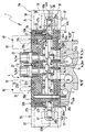
- the figure shows a total denoted by reference numeral 1 pilot-operated multi-way valve, as an example as a component a valve assembly, in addition, at least one more preferably plate-like fluid distributor.
- 2 has, on which the multi-way valve 1 - by means of suitable Fasteners 3 - is releasably attached.
- the multi-way valve 1 serves to control fluid flows, wherein it is in the medium to be controlled in particular to Compressed air acts. In principle, it can also be to act a different gaseous or hydraulic fluid.
- the multi-way valve 1 has a main valve 4, which with at least one and in the embodiment with two pilot valves 5a, 5b is combined to form an assembly.
- the pilot valves 5a, 5b serve the controlled fluid admission an elongate valve spool 6 of the main valve 4, to shift it linearly and as desired position.
- pilot valves 5a, 5b are electrically actuated types and executed in the embodiment as solenoid valves. In principle, however, would be other types of valves used as pilot valves, such as piezo valves.
- the main valve 4 has a main valve housing 7 with a elongated, one-piece housing main part 8, in which a in Longitudinal slide valve 12 formed that is, at least the most of the length of the valve spool 6 engaging control section 13 of the valve spool 6 absorbs.
- This control section 13 serves the connection between the side opening into the slider recording Valve channels 14 to control by depending on the position these valve channels 14 fluidly in a predetermined pattern connects or disconnects from each other.
- the valve spool as in the embodiment as a spool executed, its control section 13 includes a plurality axially alternately successively arranged longitudinal sections larger and smaller diameter.
- a length portion of smaller diameter of the control section 13 to lie within a sealing means 15, results in between an annular overflow section, which allows the fluid to pass between the adjacent lengths the slide holder 12 and with this to flow over connected valve channels.
- the valve spool 6 is in the region of its two axial ends each with a controlled Fluidbeetzschung enabling Drive section 16a, 16b equipped.
- everyone Drive section 16a, 16b has for this purpose one of the Fluid acted upon end face 17.
- both drive sections 16a, 16b are integral with the control section 13, wherein the entire valve spool 6 is a one-piece structure as a whole.
- the diameter of the drive sections 16a, 16b the diameter of the longitudinal sections larger Diameter of the control section 13 corresponds. Indeed it would be readily possible, the drive sections 16a, 16b as with respect to the control section 13 separate components perform.
- the drive sections 16a, 16b piston-like shape with a Outer diameter which is greater than that of the longitudinal sections larger diameter of the control section 13th
- the fluid loading of the drive sections 16a, 16b becomes each controlled by one of the two pilot valves 5a, 5b. This allows the valve spool 6 in opposite Shift directions of its longitudinal axis and as needed position.
- the multi-way valve 1 a 4/2 valve functionality.
- the multi-way valve 1 with only one Pilot valve 5a if, by other means, For example, a spring device, a provision of Valve spool 6 is ensured in a basic position.
- valve channels 14 are, inter alia, a Feeding channel 14a, the axially on both sides of each one Venting channel 14b, 14c is flanked. These channels communicate with in the fluid distributor 2 extending fluid distribution channels 18, fed and discharged through which the pressure medium becomes.
- Two further valve channels 14 are as working channels 14d, 14e trained and lead, for example, to the fluid distributor 2 opposite top of the housing main body. 8 out. There they are provided with connection means 22, which is the enable in particular detachable connection of fluid lines, leading to a consumer to be operated, for example to a drive activatable by fluid force.
- the main valve 4 is designed in the embodiment so that not only the control section 13 but also the drive sections 16a, 16b and thus the entire valve spool 6 lies within the one-piece housing main part 8.
- the valve spool 6 protrudes with its the drive sections 16a, 16b forming end portions each in a frontal End portion 23a, 23b of the slider receptacle 12 in, by external sealing means 15 'from the central area the slide holder 12 is separated, in which the Control section 13 is located.
- the slider receptacle 12 is at a in the drawing right first end face by a front-side wall portion 24 of the housing main part. 8 tightly closed.
- the frontal wall portion 24 is so one-piece component of the slide holder 12 circumferentially enclosing housing body 8.
- the slider receptacle 12 from the housing body 8 not limited, so that they total in the manner of a blind hole is formed in the housing main body 8.
- Your longitudinal axis runs parallel to the longitudinal axis of the housing main part 8th.
- the slider receptacle 12 is through a separate cover part 25 of the main valve housing 7 under Sealing and in particular releasably closed.
- the in the region of the first end face of the slide holder 12th arranged first pilot valve 5a is partially in unit with the housing main part 8 of the main valve housing. 7 educated.
- the first pilot valve 5a includes a bottom part 26 a, that of the front wall portion 24th defining end portion of the housing main body 8 is formed is.
- a mounting interface 27a is formed, the one integral with the housing main body 8 executed Pilot valve seat 28a has. The latter is expediently recessed a little way within the housing main part 8 housed.
- the bottom part 26a has the first pilot valve 5a via a head piece 32, which is a movable pilot member 33, which is a bit far from the below as a pilot housing 34 designated housing of the head piece 32 stands out.
- the pilot member 32 is in the embodiment formed by a movable armature 35 or coupled with this movement, the at least one in the Pre-control housing 34 associated solenoid coil 36 assigned is that via externally accessible electrical contact means 37 can be acted upon by an excitation voltage.
- the header 32 is mounted to the mounting interface 27a, wherein the pilot housing 34 directly on the front side the housing main part 8 is applied and wherein the pilot member 33, a position opposite the pilot valve seat 28a occupies.
- the attachment to the main valve housing 7 takes place for example, by means of dash-dotted lines indicated fastening screws 38 or other fasteners.
- the housing main part 8 is made Plastic material, if necessary by fibers or other Elements can be reinforced. It is by pouring, in particular produced by injection molding.
- the pilot valve seat 28a may be an integral part of the housing body 8 are made directly. A such one piece of housing main body 8 and pilot valve seat 28a, however, is also metallic Construction readily possible.
- the pilot valve seat 28a defines the mouth of a pilot feed passage 42a, the one for actuating the valve spool 6 introduces required pressure medium. In the embodiment he branches for this purpose within the housing main body 8 from the feed channel 14a.
- the pilot valve seat 28a is in one of a frontal depression of the housing main part 8 defined Valve chamber 43 a, in which the pilot member 33 protrudes. From her goes from a pilot control working channel 44a, the wall the housing main part 8 passes through and in the first front end portion 23a of the slider receptacle 12 opens.
- a pilot exhaust passage 45a is provided, the - in particular on the pilot member 33 over - the Valve chamber 43a connects to the environment, where he has a the back of the pilot member 33 opposite Vent valve seat 46a has.
- the first pilot valve 5a with a 3/2-valve function operate.
- the pilot control element 33 is under the action of a schematically indicated spring 47 on the pilot valve seat 28a and blocks the pilot feed passage 42a. simultaneously is the front end portion 23a via the pilot working channel 44a and the pilot exhaust passage 45a to Atmosphere vented.
- the second pilot valve 5b can thus the valve spool. 6 in the drawing to the right in the below the midline shown first switch position spent.
- the main difference between the two pilot valves 5a, 5b is that the second pilot valve 5b, the bottom part 26b is not an integral part of the Housing main part 8, but from the separate from the housing main body 8 executed lid part 25 is formed. consequently is located at the second pilot valve 5b also the mounting interface 27b and the pilot valve seat 28b on the cover part 25.
- the operation of the two pilot valves 5a, 5b is identical, so that the valve slide. 6 through coordinated admission and venting the front end portions 23a, 23b of the slider receptacle 12 optionally shifted in one or the other direction can be.
- the bottom part 26b is formed by the lid part 25 is a slight separation from the housing main body 8 possible, so that the open end the slide holder 12 is accessible to the valve spool 6 and install the sealant 15 and if necessary to be able to uninstall.
- the first pilot valve 5a is so formed and arranged that its pilot valve seat 28a to lie in the axial extension of the slide holder 12 comes.
- the slide holder 12 at the first end immediately is closed by the housing main part 8.
- the first pilot valve 5a so on the Front side of the housing main body 8 to place that in axial extension of the slide holder 12 lying zone is not occupied, so that even on this front side of a removable Cover for the slide holder 12 are provided can.
- this cover then has no function regarding of the first pilot valve 5a.
- dash-dotted lines at 48 indicate that if necessary, at least one pilot valve 48 also on the longitudinal side can be placed on the main valve 4, in particular at the top of the main valve housing 7.
- a mounting interface 27c and at least one associated pilot valve seat 28 c as an integral part of the housing main part. 8 arranged on the longitudinal side and with a head piece 32nd of the respective pilot valve 48 equipped.
- one or two pilot valves provided in a corresponding manner alongside the housing main body 8 become.
- the multi-way valve 1 has two pilot valves, there is also the possibility of this to a pilot unit to summarize, as in the drawing at 52 indicated by dash-dotted lines.
- a pilot unit to summarize, as in the drawing at 52 indicated by dash-dotted lines.
- first and second pilot valves 5a, 5b it should be mentioned that these each additionally with a manual override device 53a, 53b are equipped. This is in each case in the assigned bottom part Integrated 26a, 26b.
- the manual override device 53 a is installed in the housing main body 8 and thus is located in the same component, too the mounting interface 27a and the pilot valve seat 28a of the associated first pilot valve 5a forms.
- the manual override device is seated 53b expediently in the lid part 25th
- the manual override 53a, 53b via a preferably plunger-like actuator 54 have, in a transverse to the longitudinal direction of the pilot member 33 aligned recess 55 of the bottom portion 26 a, 26b is slidably disposed, wherein the recess 55 at one end to the outside of the bottom part 26 and the other in the valve chamber 43 opens.
- the actuator 54 has a preferably formed as an inclined surface Beaufschlagungspartie 56, which engages under the pilot member 33 and the associated Pilot valve seat 28a, 28b lifts off when the actuator 54 is displaced in the direction of the pilot member 33.
- the displacement of the actuator 54 may be caused manually become.
- the actuator 54 has the rear side an externally accessible actuating part 57.
Landscapes
- Engineering & Computer Science (AREA)
- Physics & Mathematics (AREA)
- Fluid Mechanics (AREA)
- Mechanical Engineering (AREA)
- General Engineering & Computer Science (AREA)
- Valve Housings (AREA)
- Fluid-Driven Valves (AREA)
- Magnetically Actuated Valves (AREA)
- Servomotors (AREA)
- Multiple-Way Valves (AREA)
Abstract
Description
Claims (16)
- Vorgesteuertes Mehrwegeventil mit einem Hauptventil (4), das ein Hauptventilgehäuse (7) und einen in einer Schieberaufnahme (12) desselben angeordneten länglichen Ventilschieber (6) aufweist, wobei der Ventilschieber (6) einen die Verbindung zwischen seitlich in die Schieberaufnahme (12) einmündenden Ventilkanälen (14) steuernden Steuerabschnitt (13) und an wenigstens einem Ende einen zur gesteuerten Fluidbeaufschlagung dienenden Antriebsabschnitt (16a, 16b) aufweist, wobei sich zumindest der den Steuerabschnitt (13) enthaltene Bestandteil der Schieberaufnahme (12) in einem einstückigen Gehäusehauptteil (8) des Ventilgehäuses (7) befindet, und mit mindestens einem mit dem Hauptventil (4) zu einer Baugruppe zusammengefassten Vorsteuerventil (5a, 5b, 48) zur Steuerung der Fluidbeaufschlagung mindestens eines Antriebsabschnittes (16a, 16b) des Ventilschiebers (6), das ein an einer mit einem Vorsteuerventilsitz (28a, 28c, 28d) ausgestatteten Montageschnittstelle (27a, 27b) montiertes und ein elektrisch betätigbares Vorsteuerglied (33) aufweisendes Kopfstück (32) besitzt, dadurch gekennzeichnet, dass mindestens eine Montageschnittstelle (27a, 27c, 27d) einschließlich des zugehörigen Vorsteuerventilsitzes (28a, 28c, 28d) ein integraler Bestandteil des Gehäusehauptteils (8) des Hauptventilgehäuses (7) ist, an das das Kopfstück (32) des betreffenden Vorsteuerventils (5a, 5b, 48) direkt angebaut ist.
- Mehrwegeventil nach Anspruch 1, dadurch gekennzeichnet, dass der Vorsteuerventilsitz (28a, 28c, 28d) einstückig mit dem Gehäusehauptteil (8) ausgebildet ist.
- Mehrwegeventil nach Anspruch 1 oder 2, dadurch gekennzeichnet, dass das Gehäusehauptteil (8) des Hauptventilgehäuses (7) aus Kunststoffmaterial besteht.
- Magnetventil nach einem der Ansprüche 1 bis 3, dadurch gekennzeichnet, dass das Gehäusehauptteil (8) längliche Gestalt hat, wobei sich mindestens eine Montageschnittstelle (27c) mit dem zugehörigen Vorsteuerventilsitz (28c) an einer Längsseite des Gehäusehauptteils (8) befindet.
- Mehrwegeventil nach einem der Ansprüche 1 bis 4, dadurch gekennzeichnet, dass das Gehäusehauptteil (8) längliche Gestalt hat, wobei sich mindestens eine Montageschnittstelle (27a) mit dem zugehörigen Vorsteuerventilsitz (28a) an einer Stirnseite des Gehäusehauptteils (8) befindet.
- Mehrwegeventil nach Anspruch 5, dadurch gekennzeichnet, dass die Schieberaufnahme (12) an der die Montageschnittstelle (27a) aufweisenden Stirnseite durch einen von dem einstückigen Gehäusehauptteil (8) gebildeten stirnseitigen Wandabschnitt (24) dicht verschlossen ist.
- Mehrwegeventil nach Anspruch 6, dadurch gekennzeichnet, dass der Vorsteuerventilsitz (28a) in axialer Verlängerung der Schieberaufnahme (12) an der der Schieberaufnahme (12) axial abgewandten Seite des Gehäusehauptteils (8) angeordnet ist.
- Mehrwegeventil nach einem der Ansprüche 1 bis 7, dadurch gekennzeichnet, dass das Vorsteuerventil (5a) mit einer in das Gehäusehauptteil (8) integrierten Handhilfsbetätigungseinrichtung (53a) ausgestattet ist.
- Mehrwegeventil nach Anspruch 8, gekennzeichnet durch ein in einer Ausnehmung (55) des Gehäusehauptteils (8) verstellbar angeordnetes, manuell von außen her betätigbares Stellglied (54) der Handhilfsbetätigungseinrichtung (53a), das mechanisch auf das zugeordnete Vorsteuerglied (33) einwirken kann.
- Mehrwegeventil nach einem der Ansprüche 1 bis 9, gekennzeichnet durch zwei elektrisch betätigbare Vorsteuerventile (5a, 5b) zur durch Fluidbeaufschlagung erfolgenden Betätigung des Ventilschiebers (6) in beiden Richtungen, wobei wenigstens ein Vorsteuerventil (5a) ein an eine mit einem Vorsteuerventilsitz (28a) ausgestattete Montageschnittstelle (27a) des Gehäusehauptteils (8) angesetztes Kopfstück (32) aufweist.
- Mehrwegeventil nach Anspruch 10, dadurch gekennzeichnet, dass der Ventilschieber (6) an beiden Enden einen fluidbeaufschlagbaren Antriebsabschnitt (16a 16b) aufweist.
- Mehrwegeventil nach Anspruch 10 oder 11, dadurch gekennzeichnet, dass die beiden Vorsteuerventile (5a, 5b) an den beiden einander entgegengesetzten Stirnseiten des Hauptventils (4) angeordnet sind, wobei eine Montageschnittstelle (27a) einschließlich des Vorsteuerventilsitzes (28a) des einen Vorsteuerventils (5a) integral mit dem Gehäusehauptteil (8) ausgebildet ist, während sich die Montageschnittstelle (27b) des anderen Vorsteuerventils (5b) an einem stirnseitig am Gehäusehauptteil (8) angeordneten, die Schieberaufnahme (12) verschließenden Deckelteil (25) befindet.
- Mehrwegeventil nach Anspruch 10 oder 11, dadurch gekennzeichnet, dass zwei Vorsteuerventile (5a, 5b) zu einer Vorsteuereinheit (52) zusammengefasst sind, die ein über zwei Vorsteuerglieder (33) verfügendes Kopfstück (32) aufweist, das an einer mit zwei integrierten Vorsteuerventilsitzen (28d) ausgestatteten Montageschnittstelle (27d) des Gehäusehauptteils (8) montiert ist.
- Mehrwegeventil nach einem der Ansprüche 1 bis 13, dadurch gekennzeichnet, dass das mindestens eine Vorsteuerventil (5a, 5b, 48) ein Magnetventil ist.
- Mehrwegeventil nach einem der Ansprüche 1 bis 14, dadurch gekennzeichnet, dass der mindestens eine Antriebsabschnitt (16a, 16b) einstückig mit dem Steuerabschnitt (13) verbunden ist.
- Mehrwegeventil nach einem der Ansprüche 1 bis 15, dadurch gekennzeichnet, dass der Ventilschieber (6) über seine gesamte Länge innerhalb des Gehäusehauptteils (8) angeordnet ist.
Applications Claiming Priority (2)
| Application Number | Priority Date | Filing Date | Title |
|---|---|---|---|
| DE10344458 | 2003-09-25 | ||
| DE2003144458 DE10344458B3 (de) | 2003-09-25 | 2003-09-25 | Vorgesteuertes Mehrwegeventil |
Publications (3)
| Publication Number | Publication Date |
|---|---|
| EP1519054A2 true EP1519054A2 (de) | 2005-03-30 |
| EP1519054A3 EP1519054A3 (de) | 2005-07-20 |
| EP1519054B1 EP1519054B1 (de) | 2007-02-21 |
Family
ID=34177937
Family Applications (1)
| Application Number | Title | Priority Date | Filing Date |
|---|---|---|---|
| EP20040019351 Expired - Lifetime EP1519054B1 (de) | 2003-09-25 | 2004-08-14 | Vorgesteuertes Mehrwegeventil |
Country Status (5)
| Country | Link |
|---|---|
| US (1) | US7207353B2 (de) |
| EP (1) | EP1519054B1 (de) |
| AT (1) | ATE354733T1 (de) |
| DE (2) | DE10344458B3 (de) |
| ES (1) | ES2279265T3 (de) |
Cited By (1)
| Publication number | Priority date | Publication date | Assignee | Title |
|---|---|---|---|---|
| EP2426388A1 (de) * | 2010-09-07 | 2012-03-07 | Festo AG & Co. KG | Vorgesteuertes Mehrwegeventil |
Families Citing this family (3)
| Publication number | Priority date | Publication date | Assignee | Title |
|---|---|---|---|---|
| US7818264B2 (en) * | 2006-06-19 | 2010-10-19 | Visa U.S.A. Inc. | Track data encryption |
| DE102015000763A1 (de) * | 2015-01-22 | 2016-07-28 | Wabco Gmbh | Bremsmodulator für ein Druckluft-Bremssystem eines Fahrzeugs |
| JP6856065B2 (ja) * | 2016-03-24 | 2021-04-07 | 株式会社タダノ | 油圧システム |
Family Cites Families (20)
| Publication number | Priority date | Publication date | Assignee | Title |
|---|---|---|---|---|
| US3516441A (en) * | 1967-10-12 | 1970-06-23 | Delta Hydraulies Co | Suspension assembly for bobbin in servo-valve |
| US3902526A (en) * | 1974-02-11 | 1975-09-02 | Scovill Manufacturing Co | Control valve for a fluid pressure system |
| US4067357A (en) * | 1974-06-14 | 1978-01-10 | Herion-Werke Kg | Pilot-operated directional control valve |
| US4191091A (en) * | 1976-07-16 | 1980-03-04 | Control Concepts, Inc. | Feathering valve assembly |
| DE3613746A1 (de) * | 1986-04-23 | 1987-10-29 | Concordia Fluidtechnik Gmbh | Ventil |
| DE3613747A1 (de) * | 1986-04-23 | 1987-10-29 | Concordia Fluidtechnik Gmbh | 5/3-ventil |
| DE3644269A1 (de) * | 1986-12-23 | 1988-07-07 | Rexroth Mannesmann Gmbh | Wegeventil |
| DE3842633A1 (de) | 1988-12-17 | 1990-06-28 | Wabco Westinghouse Steuerung | Vorgesteuertes mehrwegeventil |
| LU87640A1 (de) * | 1989-12-13 | 1990-03-13 | Hydrolux Sarl | Lagegeregeltes proportionalwegeventil |
| CA2008694A1 (en) * | 1990-01-26 | 1991-07-26 | Ronald F. Howarth | Valve control system |
| DE4023806C2 (de) * | 1990-07-24 | 1993-11-25 | Mannesmann Ag | Multifunktions-Mehrwegeschieberventil |
| DE4110926C2 (de) * | 1991-04-04 | 1996-04-04 | Rexroth Mannesmann Gmbh | Einstellbares Druckbegrenzungsventil |
| DE9310438U1 (de) * | 1993-07-13 | 1993-09-16 | Festo Kg, 73734 Esslingen | Ventilstation |
| EP0655575B2 (de) * | 1993-11-30 | 2007-03-28 | Smc Corporation | Servogesteuertes Mehrweg-Magnetventil |
| US5775374A (en) * | 1994-01-06 | 1998-07-07 | Koganei Corporation | Solenoid controlled valve |
| US5996628A (en) * | 1996-01-16 | 1999-12-07 | Saturn Electronics & Engineering, Inc. | Proportional variable force solenoid control valve |
| US5913577A (en) * | 1996-12-09 | 1999-06-22 | Caterpillar Inc. | Pilot stage of an electrohydraulic control valve |
| DE29712709U1 (de) * | 1997-07-18 | 1997-09-18 | Festo Kg, 73734 Esslingen | Mehrwegeventil |
| US6192937B1 (en) * | 1999-04-26 | 2001-02-27 | Mac Valves, Inc. | Pilot operated pneumatic valve |
| DE19937974B4 (de) * | 1999-08-11 | 2004-03-18 | Festo Ag & Co. | Ventileinrichtung |
-
2003
- 2003-09-25 DE DE2003144458 patent/DE10344458B3/de not_active Expired - Fee Related
-
2004
- 2004-08-14 ES ES04019351T patent/ES2279265T3/es not_active Expired - Lifetime
- 2004-08-14 EP EP20040019351 patent/EP1519054B1/de not_active Expired - Lifetime
- 2004-08-14 AT AT04019351T patent/ATE354733T1/de not_active IP Right Cessation
- 2004-08-14 DE DE200450002941 patent/DE502004002941D1/de not_active Expired - Lifetime
- 2004-09-21 US US10/946,300 patent/US7207353B2/en not_active Expired - Fee Related
Cited By (1)
| Publication number | Priority date | Publication date | Assignee | Title |
|---|---|---|---|---|
| EP2426388A1 (de) * | 2010-09-07 | 2012-03-07 | Festo AG & Co. KG | Vorgesteuertes Mehrwegeventil |
Also Published As
| Publication number | Publication date |
|---|---|
| US20050067030A1 (en) | 2005-03-31 |
| DE502004002941D1 (de) | 2007-04-05 |
| EP1519054A3 (de) | 2005-07-20 |
| DE10344458B3 (de) | 2005-05-25 |
| EP1519054B1 (de) | 2007-02-21 |
| ATE354733T1 (de) | 2007-03-15 |
| ES2279265T3 (es) | 2007-08-16 |
| US7207353B2 (en) | 2007-04-24 |
Similar Documents
| Publication | Publication Date | Title |
|---|---|---|
| EP2479465B1 (de) | Ventileinrichtung mit Handhilfsbetätigungseinrichtung | |
| DE3842633A1 (de) | Vorgesteuertes mehrwegeventil | |
| DE3931761C2 (de) | Elektro-pneumatisches Regelventil mit Relaisfunktion | |
| EP1939461A2 (de) | Modulares pneumatisches Schieberventil | |
| DE102004015661B4 (de) | Elektropneumatisches Ventil, insbesondere Vorsteuerventil für ein pneumatisches Wegeventil | |
| DE102005038621B4 (de) | Pneumatisches Wegeventil mit mindestens einem Ventilschieber | |
| DE10344458B3 (de) | Vorgesteuertes Mehrwegeventil | |
| DE69811309T2 (de) | Vorgesteuertes Lenkungsregelventil | |
| DE4011908C3 (de) | Mehrwegeventil | |
| DE10014906B4 (de) | Mehrwegeventil (Deckelbefestigung) | |
| EP0686775B2 (de) | Elektropneumatische Ventileinrichtung | |
| EP1281001A1 (de) | Ventilanordnung mit einem über einen offenen längenabschnitt verfügenden internen strömungskanal | |
| EP0994003A2 (de) | Ventileinrichtung | |
| EP1878958B1 (de) | Ventilanordnung | |
| DE102007025567A1 (de) | Elektropneumatisches Ventil, insbesondere Vorsteuerventil eines pneumatischen Wegeventils | |
| DE102006008158B4 (de) | Luftfederungseinrichtung für ein Kraftfahrzeug mit Luftfederbälgen | |
| DE102006040052A1 (de) | Mehrwegeventil mit Zentriereinrichtung | |
| DE102006030468B3 (de) | Magnetventil | |
| DE10116507B4 (de) | Ventilanordnung | |
| DE19824664C2 (de) | Mehrwegeventil | |
| EP1752693B1 (de) | Magnetventileinrichtung | |
| DE10120320B4 (de) | Vorgesteuertes Ventil mit einem Backupventil | |
| DE20019705U1 (de) | Piezo-Biegewandlereinheit und damit ausgestattetes Piezoventil | |
| EP2140181B1 (de) | Wegeventil, sowie ventilanordnung | |
| DE3914278C2 (de) | Druckregler |
Legal Events
| Date | Code | Title | Description |
|---|---|---|---|
| PUAI | Public reference made under article 153(3) epc to a published international application that has entered the european phase |
Free format text: ORIGINAL CODE: 0009012 |
|
| AK | Designated contracting states |
Kind code of ref document: A2 Designated state(s): AT BE BG CH CY CZ DE DK EE ES FI FR GB GR HU IE IT LI LU MC NL PL PT RO SE SI SK TR |
|
| AX | Request for extension of the european patent |
Extension state: AL HR LT LV MK |
|
| PUAL | Search report despatched |
Free format text: ORIGINAL CODE: 0009013 |
|
| AK | Designated contracting states |
Kind code of ref document: A3 Designated state(s): AT BE BG CH CY CZ DE DK EE ES FI FR GB GR HU IE IT LI LU MC NL PL PT RO SE SI SK TR |
|
| AX | Request for extension of the european patent |
Extension state: AL HR LT LV MK |
|
| 17P | Request for examination filed |
Effective date: 20050706 |
|
| AKX | Designation fees paid |
Designated state(s): AT BE BG CH CY CZ DE DK EE ES FI FR GB GR HU IE IT LI LU MC NL PL PT RO SE SI SK TR |
|
| GRAP | Despatch of communication of intention to grant a patent |
Free format text: ORIGINAL CODE: EPIDOSNIGR1 |
|
| GRAS | Grant fee paid |
Free format text: ORIGINAL CODE: EPIDOSNIGR3 |
|
| GRAA | (expected) grant |
Free format text: ORIGINAL CODE: 0009210 |
|
| AK | Designated contracting states |
Kind code of ref document: B1 Designated state(s): AT BE BG CH CY CZ DE DK EE ES FI FR GB GR HU IE IT LI LU MC NL PL PT RO SE SI SK TR |
|
| PG25 | Lapsed in a contracting state [announced via postgrant information from national office to epo] |
Ref country code: IE Free format text: LAPSE BECAUSE OF FAILURE TO SUBMIT A TRANSLATION OF THE DESCRIPTION OR TO PAY THE FEE WITHIN THE PRESCRIBED TIME-LIMIT Effective date: 20070221 Ref country code: FI Free format text: LAPSE BECAUSE OF FAILURE TO SUBMIT A TRANSLATION OF THE DESCRIPTION OR TO PAY THE FEE WITHIN THE PRESCRIBED TIME-LIMIT Effective date: 20070221 Ref country code: DK Free format text: LAPSE BECAUSE OF FAILURE TO SUBMIT A TRANSLATION OF THE DESCRIPTION OR TO PAY THE FEE WITHIN THE PRESCRIBED TIME-LIMIT Effective date: 20070221 Ref country code: SI Free format text: LAPSE BECAUSE OF FAILURE TO SUBMIT A TRANSLATION OF THE DESCRIPTION OR TO PAY THE FEE WITHIN THE PRESCRIBED TIME-LIMIT Effective date: 20070221 Ref country code: PL Free format text: LAPSE BECAUSE OF FAILURE TO SUBMIT A TRANSLATION OF THE DESCRIPTION OR TO PAY THE FEE WITHIN THE PRESCRIBED TIME-LIMIT Effective date: 20070221 |
|
| REG | Reference to a national code |
Ref country code: GB Ref legal event code: FG4D Free format text: NOT ENGLISH |
|
| REG | Reference to a national code |
Ref country code: SE Ref legal event code: TRGR |
|
| GBT | Gb: translation of ep patent filed (gb section 77(6)(a)/1977) |
Effective date: 20070221 |
|
| REG | Reference to a national code |
Ref country code: CH Ref legal event code: EP |
|
| REF | Corresponds to: |
Ref document number: 502004002941 Country of ref document: DE Date of ref document: 20070405 Kind code of ref document: P |
|
| REG | Reference to a national code |
Ref country code: IE Ref legal event code: FG4D Free format text: LANGUAGE OF EP DOCUMENT: GERMAN |
|
| PG25 | Lapsed in a contracting state [announced via postgrant information from national office to epo] |
Ref country code: BG Free format text: LAPSE BECAUSE OF FAILURE TO SUBMIT A TRANSLATION OF THE DESCRIPTION OR TO PAY THE FEE WITHIN THE PRESCRIBED TIME-LIMIT Effective date: 20070522 |
|
| PG25 | Lapsed in a contracting state [announced via postgrant information from national office to epo] |
Ref country code: PT Free format text: LAPSE BECAUSE OF FAILURE TO SUBMIT A TRANSLATION OF THE DESCRIPTION OR TO PAY THE FEE WITHIN THE PRESCRIBED TIME-LIMIT Effective date: 20070723 |
|
| REG | Reference to a national code |
Ref country code: ES Ref legal event code: FG2A Ref document number: 2279265 Country of ref document: ES Kind code of ref document: T3 |
|
| ET | Fr: translation filed | ||
| REG | Reference to a national code |
Ref country code: IE Ref legal event code: FD4D |
|
| PG25 | Lapsed in a contracting state [announced via postgrant information from national office to epo] |
Ref country code: SK Free format text: LAPSE BECAUSE OF FAILURE TO SUBMIT A TRANSLATION OF THE DESCRIPTION OR TO PAY THE FEE WITHIN THE PRESCRIBED TIME-LIMIT Effective date: 20070221 |
|
| PLBE | No opposition filed within time limit |
Free format text: ORIGINAL CODE: 0009261 |
|
| STAA | Information on the status of an ep patent application or granted ep patent |
Free format text: STATUS: NO OPPOSITION FILED WITHIN TIME LIMIT |
|
| PG25 | Lapsed in a contracting state [announced via postgrant information from national office to epo] |
Ref country code: CZ Free format text: LAPSE BECAUSE OF FAILURE TO SUBMIT A TRANSLATION OF THE DESCRIPTION OR TO PAY THE FEE WITHIN THE PRESCRIBED TIME-LIMIT Effective date: 20070221 Ref country code: RO Free format text: LAPSE BECAUSE OF FAILURE TO SUBMIT A TRANSLATION OF THE DESCRIPTION OR TO PAY THE FEE WITHIN THE PRESCRIBED TIME-LIMIT Effective date: 20070221 |
|
| 26N | No opposition filed |
Effective date: 20071122 |
|
| BERE | Be: lapsed |
Owner name: FESTO A.G. & CO. Effective date: 20070831 |
|
| PG25 | Lapsed in a contracting state [announced via postgrant information from national office to epo] |
Ref country code: MC Free format text: LAPSE BECAUSE OF NON-PAYMENT OF DUE FEES Effective date: 20070831 Ref country code: GR Free format text: LAPSE BECAUSE OF FAILURE TO SUBMIT A TRANSLATION OF THE DESCRIPTION OR TO PAY THE FEE WITHIN THE PRESCRIBED TIME-LIMIT Effective date: 20070522 |
|
| PG25 | Lapsed in a contracting state [announced via postgrant information from national office to epo] |
Ref country code: BE Free format text: LAPSE BECAUSE OF NON-PAYMENT OF DUE FEES Effective date: 20070831 |
|
| PG25 | Lapsed in a contracting state [announced via postgrant information from national office to epo] |
Ref country code: AT Free format text: LAPSE BECAUSE OF NON-PAYMENT OF DUE FEES Effective date: 20070814 |
|
| PG25 | Lapsed in a contracting state [announced via postgrant information from national office to epo] |
Ref country code: EE Free format text: LAPSE BECAUSE OF FAILURE TO SUBMIT A TRANSLATION OF THE DESCRIPTION OR TO PAY THE FEE WITHIN THE PRESCRIBED TIME-LIMIT Effective date: 20070221 |
|
| REG | Reference to a national code |
Ref country code: CH Ref legal event code: PL |
|
| PG25 | Lapsed in a contracting state [announced via postgrant information from national office to epo] |
Ref country code: LI Free format text: LAPSE BECAUSE OF NON-PAYMENT OF DUE FEES Effective date: 20080831 Ref country code: CH Free format text: LAPSE BECAUSE OF NON-PAYMENT OF DUE FEES Effective date: 20080831 |
|
| PG25 | Lapsed in a contracting state [announced via postgrant information from national office to epo] |
Ref country code: CY Free format text: LAPSE BECAUSE OF FAILURE TO SUBMIT A TRANSLATION OF THE DESCRIPTION OR TO PAY THE FEE WITHIN THE PRESCRIBED TIME-LIMIT Effective date: 20070221 |
|
| PG25 | Lapsed in a contracting state [announced via postgrant information from national office to epo] |
Ref country code: LU Free format text: LAPSE BECAUSE OF NON-PAYMENT OF DUE FEES Effective date: 20070814 |
|
| PG25 | Lapsed in a contracting state [announced via postgrant information from national office to epo] |
Ref country code: HU Free format text: LAPSE BECAUSE OF FAILURE TO SUBMIT A TRANSLATION OF THE DESCRIPTION OR TO PAY THE FEE WITHIN THE PRESCRIBED TIME-LIMIT Effective date: 20070822 Ref country code: TR Free format text: LAPSE BECAUSE OF FAILURE TO SUBMIT A TRANSLATION OF THE DESCRIPTION OR TO PAY THE FEE WITHIN THE PRESCRIBED TIME-LIMIT Effective date: 20070221 |
|
| PGFP | Annual fee paid to national office [announced via postgrant information from national office to epo] |
Ref country code: SE Payment date: 20130819 Year of fee payment: 10 |
|
| REG | Reference to a national code |
Ref country code: SE Ref legal event code: EUG |
|
| PG25 | Lapsed in a contracting state [announced via postgrant information from national office to epo] |
Ref country code: SE Free format text: LAPSE BECAUSE OF NON-PAYMENT OF DUE FEES Effective date: 20140815 |
|
| REG | Reference to a national code |
Ref country code: FR Ref legal event code: PLFP Year of fee payment: 13 |
|
| PGFP | Annual fee paid to national office [announced via postgrant information from national office to epo] |
Ref country code: NL Payment date: 20160824 Year of fee payment: 13 |
|
| PGFP | Annual fee paid to national office [announced via postgrant information from national office to epo] |
Ref country code: ES Payment date: 20160829 Year of fee payment: 13 |
|
| REG | Reference to a national code |
Ref country code: FR Ref legal event code: PLFP Year of fee payment: 14 |
|
| PGFP | Annual fee paid to national office [announced via postgrant information from national office to epo] |
Ref country code: FR Payment date: 20170823 Year of fee payment: 14 Ref country code: IT Payment date: 20170824 Year of fee payment: 14 Ref country code: GB Payment date: 20170717 Year of fee payment: 14 |
|
| REG | Reference to a national code |
Ref country code: NL Ref legal event code: MM Effective date: 20170901 |
|
| PG25 | Lapsed in a contracting state [announced via postgrant information from national office to epo] |
Ref country code: NL Free format text: LAPSE BECAUSE OF NON-PAYMENT OF DUE FEES Effective date: 20170901 |
|
| REG | Reference to a national code |
Ref country code: ES Ref legal event code: FD2A Effective date: 20181029 |
|
| PG25 | Lapsed in a contracting state [announced via postgrant information from national office to epo] |
Ref country code: ES Free format text: LAPSE BECAUSE OF NON-PAYMENT OF DUE FEES Effective date: 20170815 |
|
| GBPC | Gb: european patent ceased through non-payment of renewal fee |
Effective date: 20180814 |
|
| PG25 | Lapsed in a contracting state [announced via postgrant information from national office to epo] |
Ref country code: IT Free format text: LAPSE BECAUSE OF NON-PAYMENT OF DUE FEES Effective date: 20180814 |
|
| PG25 | Lapsed in a contracting state [announced via postgrant information from national office to epo] |
Ref country code: FR Free format text: LAPSE BECAUSE OF NON-PAYMENT OF DUE FEES Effective date: 20180831 |
|
| PG25 | Lapsed in a contracting state [announced via postgrant information from national office to epo] |
Ref country code: GB Free format text: LAPSE BECAUSE OF NON-PAYMENT OF DUE FEES Effective date: 20180814 |
|
| REG | Reference to a national code |
Ref country code: DE Ref legal event code: R082 Ref document number: 502004002941 Country of ref document: DE Representative=s name: PATENTANWAELTE MAGENBAUER & KOLLEGEN PARTNERSC, DE Ref country code: DE Ref legal event code: R081 Ref document number: 502004002941 Country of ref document: DE Owner name: FESTO SE & CO. KG, DE Free format text: FORMER OWNER: FESTO AG & CO. KG, 73734 ESSLINGEN, DE Ref country code: DE Ref legal event code: R081 Ref document number: 502004002941 Country of ref document: DE Owner name: FESTO AG & CO. KG, DE Free format text: FORMER OWNER: FESTO AG & CO. KG, 73734 ESSLINGEN, DE |
|
| PGFP | Annual fee paid to national office [announced via postgrant information from national office to epo] |
Ref country code: DE Payment date: 20200530 Year of fee payment: 17 |
|
| REG | Reference to a national code |
Ref country code: DE Ref legal event code: R119 Ref document number: 502004002941 Country of ref document: DE |
|
| PG25 | Lapsed in a contracting state [announced via postgrant information from national office to epo] |
Ref country code: DE Free format text: LAPSE BECAUSE OF NON-PAYMENT OF DUE FEES Effective date: 20220301 |