EP1519089A1 - Soupape et méthode pour le montage d'un tiroir dans un boitier de manière étanche et faible-friction - Google Patents
Soupape et méthode pour le montage d'un tiroir dans un boitier de manière étanche et faible-friction Download PDFInfo
- Publication number
- EP1519089A1 EP1519089A1 EP04104635A EP04104635A EP1519089A1 EP 1519089 A1 EP1519089 A1 EP 1519089A1 EP 04104635 A EP04104635 A EP 04104635A EP 04104635 A EP04104635 A EP 04104635A EP 1519089 A1 EP1519089 A1 EP 1519089A1
- Authority
- EP
- European Patent Office
- Prior art keywords
- valve
- valve housing
- spool
- housing
- adjacent
- Prior art date
- Legal status (The legal status is an assumption and is not a legal conclusion. Google has not performed a legal analysis and makes no representation as to the accuracy of the status listed.)
- Granted
Links
- 238000000034 method Methods 0.000 title claims abstract description 14
- 239000000463 material Substances 0.000 claims abstract description 67
- 238000001816 cooling Methods 0.000 claims abstract description 13
- 238000010438 heat treatment Methods 0.000 claims abstract description 10
- 238000001746 injection moulding Methods 0.000 claims description 5
- 238000004519 manufacturing process Methods 0.000 claims description 4
- 239000007769 metal material Substances 0.000 claims description 3
- 238000003825 pressing Methods 0.000 claims description 3
- 239000012815 thermoplastic material Substances 0.000 claims description 3
- 239000002184 metal Substances 0.000 claims description 2
- 238000009434 installation Methods 0.000 abstract 1
- 238000007789 sealing Methods 0.000 description 3
- 230000001419 dependent effect Effects 0.000 description 2
- 239000004033 plastic Substances 0.000 description 2
- 238000005245 sintering Methods 0.000 description 2
- 239000000243 solution Substances 0.000 description 2
- 150000001875 compounds Chemical class 0.000 description 1
- 230000003993 interaction Effects 0.000 description 1
- 238000005498 polishing Methods 0.000 description 1
- 238000005507 spraying Methods 0.000 description 1
Images
Classifications
-
- F—MECHANICAL ENGINEERING; LIGHTING; HEATING; WEAPONS; BLASTING
- F16—ENGINEERING ELEMENTS AND UNITS; GENERAL MEASURES FOR PRODUCING AND MAINTAINING EFFECTIVE FUNCTIONING OF MACHINES OR INSTALLATIONS; THERMAL INSULATION IN GENERAL
- F16K—VALVES; TAPS; COCKS; ACTUATING-FLOATS; DEVICES FOR VENTING OR AERATING
- F16K27/00—Construction of housing; Use of materials therefor
- F16K27/04—Construction of housing; Use of materials therefor of sliding valves
- F16K27/041—Construction of housing; Use of materials therefor of sliding valves cylindrical slide valves
-
- F—MECHANICAL ENGINEERING; LIGHTING; HEATING; WEAPONS; BLASTING
- F16—ENGINEERING ELEMENTS AND UNITS; GENERAL MEASURES FOR PRODUCING AND MAINTAINING EFFECTIVE FUNCTIONING OF MACHINES OR INSTALLATIONS; THERMAL INSULATION IN GENERAL
- F16K—VALVES; TAPS; COCKS; ACTUATING-FLOATS; DEVICES FOR VENTING OR AERATING
- F16K11/00—Multiple-way valves, e.g. mixing valves; Pipe fittings incorporating such valves
- F16K11/02—Multiple-way valves, e.g. mixing valves; Pipe fittings incorporating such valves with all movable sealing faces moving as one unit
- F16K11/06—Multiple-way valves, e.g. mixing valves; Pipe fittings incorporating such valves with all movable sealing faces moving as one unit comprising only sliding valves, i.e. sliding closure elements
- F16K11/065—Multiple-way valves, e.g. mixing valves; Pipe fittings incorporating such valves with all movable sealing faces moving as one unit comprising only sliding valves, i.e. sliding closure elements with linearly sliding closure members
- F16K11/07—Multiple-way valves, e.g. mixing valves; Pipe fittings incorporating such valves with all movable sealing faces moving as one unit comprising only sliding valves, i.e. sliding closure elements with linearly sliding closure members with cylindrical slides
Definitions
- the application relates to a valve and a method for a pressure-tight, low-friction arrangement of an associated valve spool in a housing according to the preamble of claim 1 or 13th
- valves that have a sealing ring (the can be mounted either on the valve spool or on the sealing housing) and valves, at where no sealing ring is provided.
- valves of the latter type it is from eminent importance that the valve spool and the interior of the valve spool surrounding valve housing must be as accurate as possible, since the friction and the Pressure tightness of a slide valve then essentially from the gap between housing and slides are dependent.
- a valve according to the invention comprises a valve spool and a in assembled state surrounding the valve spool valve housing with a tubular inner recess and is characterized in that the Valve slide material at least in the assembled state of the Valve housing adjacent areas a lower modulus of elasticity and a higher Thermal expansion coefficient than that on the inner recess of the valve housing adjacent valve housing material.
- the valve housing material adjoining the inner recess of the valve housing preferably has a modulus of elasticity of ⁇ 0.5 ⁇ 10 -5 N / mm 2 to ⁇ 10 ⁇ 10 -5 N / mm 2 , more preferably 0.75 ⁇ 10 -5 N / mm 2 to ⁇ 7.5 x 10 -5 N / mm 2 , more preferably from ⁇ 1 x 10 -5 N / mm 2 to ⁇ 5 x 10 -5 N / mm 2 , still preferably ⁇ 1.25 x 10 -5 N / mm 2 to ⁇ 3 x 10 -5 N / mm 2, and most preferably from ⁇ 1.5 x 10 -5 N / mm 2 to ⁇ 2.5 x 10 -5 N / mm 2 .
- the valve gate material preferably has a Young's modulus of elastic modulus of ⁇ 0.25 ⁇ 10 -7 N / mm 2 to ⁇ 10 ⁇ 10 -7 N / mm 2 , more preferably ⁇ 0, at least in the regions adjacent to the valve housing in the assembled state.
- the ratio of modulus of elasticity of the inner recess of the valve housing adjacent valve body material to modulus of elasticity of the valve gate material at least in the assembled state of the valve housing adjacent Ranges is preferably from ⁇ 1: 10 to ⁇ 1: 1000, still preferably from ⁇ 1: 25 to ⁇ 1: 750, still preferably from ⁇ 1: 50 to ⁇ 1: 500, more preferably from ⁇ 1: 75 to ⁇ 1: 300, and most preferably from ⁇ 1: 100 to ⁇ 1: 200.
- the valve housing material adjoining the inner recess of the valve housing preferably has a thermal expansion coefficient of ⁇ 1 ⁇ 10 -6 1 / K to ⁇ 100 ⁇ 10 -6 1 / K, more preferably 2.5 ⁇ 10 -6 1 / K to ⁇ 75 x 10 -6 1 / K, more preferably from ⁇ 5 x 10 -6 N / mm 2 to ⁇ 50 x 10 -6 1 / K, more preferably from ⁇ 10 x 10 -6 1 / K to ⁇ 25 x 10 - 5 1 / K and most preferably from ⁇ 12 x 10 -6 1 / K to ⁇ 20 x 10 -6 1 / K.
- the valve slide material preferably has a coefficient of thermal expansion of at least den 1 ⁇ 10 -5 1 / K to ⁇ 100 ⁇ 10 -5 1 / K, more preferably 2.5 ⁇ 10 -5 1, at least in the regions adjoining the valve housing in the assembled state / K to ⁇ 75 x 10 -5 1 / K, more preferably from ⁇ 5 x 10 -5 N / mm 2 to ⁇ 60 x 10 -5 1 / K, more preferably from ⁇ 10 x 10 -5 1 / K to ⁇ 40 x 10 -5 1 / K and most preferably from ⁇ 12 x 10 -5 1 / K to ⁇ 30 x 10 -5 1 / K.
- the ratio of coefficient of thermal expansion of the internal recess of the Valve body adjacent valve housing material to the coefficient of thermal expansion of Valve slide material at least in the assembled state of the Valve housing adjacent areas is preferably from> 1: 1 to ⁇ 1: 100, still preferred from ⁇ 1: 2 to ⁇ 1.75, more preferably from ⁇ 1: 5 to ⁇ 150, still more preferably from ⁇ 1: 7.5 to ⁇ 1:25, and most preferably from ⁇ 1: 10 to ⁇ 1.15.
- the valve slide in the initial state has a larger radial maximum diameter than the diameter of the inner recess of the Valve housing and is by heating above the pour point of the valve material of the Area of the valve spool, which in the assembled state to the valve housing adjoins and subsequent cooling in the inner recess einp motherboard.
- the housing consists of a metallic Material consists, which is preferably produced in a sintering process.
- valve slide is at least in Subregions of a thermoplastic material, which preferably by injection molding is formed.
- valve spool is only in the in assembled state to the valve housing adjacent areas of a Material, which has a lower modulus of elasticity and a higher Thermal expansion coefficient than that on the inner recess of the valve housing adjacent valve housing material, in the remaining areas but from a similar or the same material as the adjacent to the inner recess of the valve housing Valve housing material. Preference is given to the former areas on the Valve body (i.e., the remaining portions of the valve spool) is applied, preferably splashed or snapped.
- step (b) supplied amount of heat and / or the period of heating so measured that after cooling, a desired gap between valve spool and valve housing established.
- valve spool When pressing the valve spool whose material at least in the compound state to the valve housing adjacent areas a lesser Elastic modulus and has a higher coefficient of thermal expansion than that of the Inner recess of the valve housing adjacent valve housing material into the Valve body these areas are put under tension. To reduce this tension now valve spool and valve housing are heated until the yield stress (generated by the different thermal expansion coefficients of the two Materials) is reached and it is a plastic deformation in the prestressed Areas of the slider comes. However, an elastic residual prestress also remains in the heated condition exist.
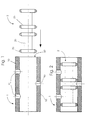
- a valve according to the invention includes a valve housing 1 and a valve spool 2.
- a valve housing 1 includes a valve housing 1 and a valve spool 2.
- additional required known components of the valve omitted.
- the valve housing 1 is preferably made of a metallic material 10 and has a plurality of control channels 40 which are controllable by the valve spool 2, as well as a tubular inner recess (inner channel) 50 on.
- the valve housing is through a Metal Injection Molding (MIM) process can be produced.
- MIM Metal Injection Molding
- the valve body can also be made two or more layers or areas of different material. Is preferred however, at least the region of the valve housing which adjoins the inner channel 50, from made a uniform material 10.
- the valve spool 2 consists of a valve body 20, which one or more (in this embodiment comprises four) slider seating surfaces 25.
- a layer 30 of a second material applied which has a smaller elastic modulus, but a greater thermal expansion has as the valve housing material 10.
- the second material is preferably a thermoplastic material. It is preferred by spraying or snapping on the Valve body 20 applied.
- valve spool 30 which adjoins the valve housing 1 in the assembled state, from another Material than the valve body 20 and the slider seat surfaces 25.
- valve body 20 and slide seat surfaces 25th of the same or a similar material as the valve housing 10.
- the entire valve spool consist of a single material, or for the Valve body 20 and / or the slider seat surfaces 25 may also be different Materials - also different to the valve housing material 10 - are selected.
- valve spool 2 has a in the initial state larger maximum outer diameter than the inner diameter of the inner channel 50.
- valve spool 2 in the valve housing now takes place as follows, that first of the valve spool 2, as indicated in the arrow direction in Fig. 1 in the Valve housing 1 is pressed.
- the material adjacent to the valve housing 30th the valve spool 2 under tension since it has a smaller elastic modulus than the housing material 10 (press fit).
- Valve housing 1 and valve spool 2 are now heated until the yield stresses of the Spool material 30 can be achieved and thus it to a plastic deformation comes; however, not all stresses within the material 30 are eliminated.
- At the Cooling now pulls the spool material 30 back more than the material of Valve housing 10, since it has a larger thermal expansion coefficient.
- residual stresses are eliminated in the spool material 30, on the other hand arises - with controlled heat addition and / or heat addition time - a precisely adjustable gap between the valve spool 2 and the valve housing 1.
- the cooling takes place preferably under control of the cooling rate and / or duration.
- valve spool After cooling, the valve spool is pressure-tight and low-friction in the Valve housing fitted, as seen in Fig. 2.
- valves of this type can be used in all areas
- Application find in which a quick and accurate fitting of a spool in a housing is needed.
Landscapes
- Engineering & Computer Science (AREA)
- General Engineering & Computer Science (AREA)
- Mechanical Engineering (AREA)
- Multiple-Way Valves (AREA)
- Sliding Valves (AREA)
Applications Claiming Priority (2)
| Application Number | Priority Date | Filing Date | Title |
|---|---|---|---|
| DE2003144407 DE10344407B4 (de) | 2003-09-25 | 2003-09-25 | Ventil und Verfahren zu einer druckdichten, reibungsarmen Anordnung eines dazugehörigen Ventilschiebers in einem Gehäuse |
| DE10344407 | 2003-09-25 |
Publications (2)
| Publication Number | Publication Date |
|---|---|
| EP1519089A1 true EP1519089A1 (fr) | 2005-03-30 |
| EP1519089B1 EP1519089B1 (fr) | 2006-07-05 |
Family
ID=34177935
Family Applications (1)
| Application Number | Title | Priority Date | Filing Date |
|---|---|---|---|
| EP20040104635 Expired - Lifetime EP1519089B1 (fr) | 2003-09-25 | 2004-09-23 | Soupape et méthode pour le montage d'un tiroir dans un boitier de manière étanche et faible-friction |
Country Status (2)
| Country | Link |
|---|---|
| EP (1) | EP1519089B1 (fr) |
| DE (2) | DE10344407B4 (fr) |
Cited By (1)
| Publication number | Priority date | Publication date | Assignee | Title |
|---|---|---|---|---|
| WO2006131913A1 (fr) * | 2005-06-06 | 2006-12-14 | I.D.E. Technologies Ltd. | Piston pour distributeur a tiroir lineaire |
Citations (4)
| Publication number | Priority date | Publication date | Assignee | Title |
|---|---|---|---|---|
| US3958792A (en) * | 1974-05-17 | 1976-05-25 | Barkelew Richard C | Valve with radially expansive valve plug |
| FR2587779A1 (fr) * | 1985-09-20 | 1987-03-27 | Joint Francais | Dispositif d'etancheite pour piston flottant |
| DE19837558A1 (de) * | 1998-08-19 | 2000-03-09 | Bosch Gmbh Robert | Ventilschieber |
| JP2001137338A (ja) * | 1999-11-15 | 2001-05-22 | Kooki Engineering:Kk | シリンジ用ピストンの摺動部材及びその製造方法 |
Family Cites Families (5)
| Publication number | Priority date | Publication date | Assignee | Title |
|---|---|---|---|---|
| US5098061A (en) * | 1988-09-02 | 1992-03-24 | The B. F. Goodrich Company | Cascaded pneumatic impulse separation system and valves therefor |
| US5248126A (en) * | 1991-09-12 | 1993-09-28 | Volkswagen A.G. | Slide for a slide valve, and method for the manufacture thereof |
| DE19509578B4 (de) * | 1995-03-16 | 2005-12-22 | Robert Bosch Gmbh | Pneumatisches Wegeventil |
| DE19802311A1 (de) * | 1998-01-22 | 1999-08-05 | Bosch Gmbh Robert | Wegeventil |
| DE19813981C2 (de) * | 1998-03-28 | 2001-12-06 | Bosch Gmbh Robert | Schiebergesteuertes Wegeventil |
-
2003
- 2003-09-25 DE DE2003144407 patent/DE10344407B4/de not_active Expired - Fee Related
-
2004
- 2004-09-23 DE DE200450000910 patent/DE502004000910D1/de not_active Expired - Lifetime
- 2004-09-23 EP EP20040104635 patent/EP1519089B1/fr not_active Expired - Lifetime
Patent Citations (4)
| Publication number | Priority date | Publication date | Assignee | Title |
|---|---|---|---|---|
| US3958792A (en) * | 1974-05-17 | 1976-05-25 | Barkelew Richard C | Valve with radially expansive valve plug |
| FR2587779A1 (fr) * | 1985-09-20 | 1987-03-27 | Joint Francais | Dispositif d'etancheite pour piston flottant |
| DE19837558A1 (de) * | 1998-08-19 | 2000-03-09 | Bosch Gmbh Robert | Ventilschieber |
| JP2001137338A (ja) * | 1999-11-15 | 2001-05-22 | Kooki Engineering:Kk | シリンジ用ピストンの摺動部材及びその製造方法 |
Non-Patent Citations (1)
| Title |
|---|
| PATENT ABSTRACTS OF JAPAN vol. 2000, no. 22 9 March 2001 (2001-03-09) * |
Cited By (2)
| Publication number | Priority date | Publication date | Assignee | Title |
|---|---|---|---|---|
| WO2006131913A1 (fr) * | 2005-06-06 | 2006-12-14 | I.D.E. Technologies Ltd. | Piston pour distributeur a tiroir lineaire |
| US7703475B2 (en) | 2005-06-06 | 2010-04-27 | I.D.E. Technologies Ltd. | Piston for a linear spool valve |
Also Published As
| Publication number | Publication date |
|---|---|
| EP1519089B1 (fr) | 2006-07-05 |
| DE502004000910D1 (de) | 2006-08-17 |
| DE10344407B4 (de) | 2006-06-08 |
| DE10344407A1 (de) | 2005-04-28 |
Similar Documents
| Publication | Publication Date | Title |
|---|---|---|
| EP0720691B1 (fr) | Pointeau pour soupape a actionnement electromagnetique et son procede de production | |
| DE4137994C2 (de) | Elektromagnetisch betätigbares Einspritzventil mit einem Düsenträger und Verfahren zur Herstellung eines Düsenträgers eines Einspritzventils | |
| EP0733162B1 (fr) | Procede de production d'un circuit magnetique pour soupape | |
| DE60218279T2 (de) | Verfahren zur Kalibrierung der beweglichen Feder von Magnetventilen | |
| DE3738877A1 (de) | Elektromagnetisches kraftstoffeinspritzventil | |
| DE4415850A1 (de) | Ventilnadel für ein elektromagnetisch betätigbares Ventil | |
| DE2110065A1 (de) | Ventil und Verfahren zu dessen Herstellung | |
| DE102017216676A1 (de) | Verfahren zur Herstellung eines dreidimensionalen Produktes | |
| DE2460185A1 (de) | Verfahren zur herstellung von dichtungselementen mit hydrodynamischer wirkung | |
| DE102005039288A1 (de) | Verfahren zur Herstellung eines festen Gehäuses | |
| DE10221100C1 (de) | Elektrisch leitfähige Dichtung sowie Verfahren und Vorrichtung zu deren Herstellung | |
| DE102007056861A1 (de) | Planetengewindetrieb | |
| EP1519089B1 (fr) | Soupape et méthode pour le montage d'un tiroir dans un boitier de manière étanche et faible-friction | |
| EP1503096A2 (fr) | Organe de retenue pour la fixation d'au moins un palier | |
| EP0309678B1 (fr) | Procédé de fabrication d'un boisseau sphérique pour un robinet à boisseau | |
| DE3852493T2 (de) | Herstellungsverfahren für eine Lochplatte für Brennstoff-Einspritzventile. | |
| WO2005049273A1 (fr) | Procede et dispositif pour arrondir par hydroerosion des zones de transition d'alesages | |
| DE3206979A1 (de) | Verbund-ventilsitz | |
| DE2227335A1 (de) | Treibriemen und verfahren zu seiner herstellung | |
| DE69000591T2 (de) | Kraftstoffeinspritzduese. | |
| DE2333812C3 (de) | Magnetkopf in Dünnschichttechnik und Verfahren zu seiner Herstellung | |
| DE4235611C2 (de) | Kunststoff-Lagergehäuse | |
| DE102005036950A1 (de) | Verfahren zur Herstellung eines metallischen Bauteils und metallisches Bauteil, insbesondere Ventilsitzbauteil | |
| DE102018010142A1 (de) | Verfahren zum Herstellen eines Kunststoff-Formteils mit integralen Haltekomponenten | |
| DE102023133515A1 (de) | Ankersystem, Ventilsystem und Magnetventil sowie Verfahren zur Herstellung eines Ventilsystems |
Legal Events
| Date | Code | Title | Description |
|---|---|---|---|
| PUAI | Public reference made under article 153(3) epc to a published international application that has entered the european phase |
Free format text: ORIGINAL CODE: 0009012 |
|
| AK | Designated contracting states |
Kind code of ref document: A1 Designated state(s): AT BE BG CH CY CZ DE DK EE ES FI FR GB GR HU IE IT LI LU MC NL PL PT RO SE SI SK TR |
|
| AX | Request for extension of the european patent |
Extension state: AL HR LT LV MK |
|
| 17P | Request for examination filed |
Effective date: 20050702 |
|
| GRAP | Despatch of communication of intention to grant a patent |
Free format text: ORIGINAL CODE: EPIDOSNIGR1 |
|
| GRAS | Grant fee paid |
Free format text: ORIGINAL CODE: EPIDOSNIGR3 |
|
| AKX | Designation fees paid |
Designated state(s): DE FR GB IT SE |
|
| GRAA | (expected) grant |
Free format text: ORIGINAL CODE: 0009210 |
|
| AK | Designated contracting states |
Kind code of ref document: B1 Designated state(s): DE FR GB IT SE |
|
| REG | Reference to a national code |
Ref country code: GB Ref legal event code: FG4D Free format text: NOT ENGLISH |
|
| REF | Corresponds to: |
Ref document number: 502004000910 Country of ref document: DE Date of ref document: 20060817 Kind code of ref document: P |
|
| REG | Reference to a national code |
Ref country code: SE Ref legal event code: TRGR |
|
| GBT | Gb: translation of ep patent filed (gb section 77(6)(a)/1977) |
Effective date: 20061004 |
|
| ET | Fr: translation filed | ||
| PLBE | No opposition filed within time limit |
Free format text: ORIGINAL CODE: 0009261 |
|
| STAA | Information on the status of an ep patent application or granted ep patent |
Free format text: STATUS: NO OPPOSITION FILED WITHIN TIME LIMIT |
|
| 26N | No opposition filed |
Effective date: 20070410 |
|
| PGFP | Annual fee paid to national office [announced via postgrant information from national office to epo] |
Ref country code: FR Payment date: 20100930 Year of fee payment: 7 Ref country code: SE Payment date: 20100921 Year of fee payment: 7 |
|
| PGFP | Annual fee paid to national office [announced via postgrant information from national office to epo] |
Ref country code: GB Payment date: 20100924 Year of fee payment: 7 |
|
| PGFP | Annual fee paid to national office [announced via postgrant information from national office to epo] |
Ref country code: IT Payment date: 20100928 Year of fee payment: 7 |
|
| GBPC | Gb: european patent ceased through non-payment of renewal fee |
Effective date: 20110923 |
|
| PG25 | Lapsed in a contracting state [announced via postgrant information from national office to epo] |
Ref country code: IT Free format text: LAPSE BECAUSE OF NON-PAYMENT OF DUE FEES Effective date: 20110923 |
|
| REG | Reference to a national code |
Ref country code: FR Ref legal event code: ST Effective date: 20120531 |
|
| REG | Reference to a national code |
Ref country code: SE Ref legal event code: EUG |
|
| PG25 | Lapsed in a contracting state [announced via postgrant information from national office to epo] |
Ref country code: FR Free format text: LAPSE BECAUSE OF NON-PAYMENT OF DUE FEES Effective date: 20110930 Ref country code: GB Free format text: LAPSE BECAUSE OF NON-PAYMENT OF DUE FEES Effective date: 20110923 |
|
| PG25 | Lapsed in a contracting state [announced via postgrant information from national office to epo] |
Ref country code: SE Free format text: LAPSE BECAUSE OF NON-PAYMENT OF DUE FEES Effective date: 20110924 |
|
| PGFP | Annual fee paid to national office [announced via postgrant information from national office to epo] |
Ref country code: DE Payment date: 20140922 Year of fee payment: 11 |
|
| REG | Reference to a national code |
Ref country code: DE Ref legal event code: R119 Ref document number: 502004000910 Country of ref document: DE |
|
| PG25 | Lapsed in a contracting state [announced via postgrant information from national office to epo] |
Ref country code: DE Free format text: LAPSE BECAUSE OF NON-PAYMENT OF DUE FEES Effective date: 20160401 |