EP1519098A1 - Elektrisch beheizbare Flüssigkeitsleitung - Google Patents
Elektrisch beheizbare Flüssigkeitsleitung Download PDFInfo
- Publication number
- EP1519098A1 EP1519098A1 EP04017169A EP04017169A EP1519098A1 EP 1519098 A1 EP1519098 A1 EP 1519098A1 EP 04017169 A EP04017169 A EP 04017169A EP 04017169 A EP04017169 A EP 04017169A EP 1519098 A1 EP1519098 A1 EP 1519098A1
- Authority
- EP
- European Patent Office
- Prior art keywords
- heating wire
- plastic layer
- liquid line
- tape
- adhesive
- Prior art date
- Legal status (The legal status is an assumption and is not a legal conclusion. Google has not performed a legal analysis and makes no representation as to the accuracy of the status listed.)
- Granted
Links
Images
Classifications
-
- F—MECHANICAL ENGINEERING; LIGHTING; HEATING; WEAPONS; BLASTING
- F16—ENGINEERING ELEMENTS AND UNITS; GENERAL MEASURES FOR PRODUCING AND MAINTAINING EFFECTIVE FUNCTIONING OF MACHINES OR INSTALLATIONS; THERMAL INSULATION IN GENERAL
- F16L—PIPES; JOINTS OR FITTINGS FOR PIPES; SUPPORTS FOR PIPES, CABLES OR PROTECTIVE TUBING; MEANS FOR THERMAL INSULATION IN GENERAL
- F16L53/00—Heating of pipes or pipe systems; Cooling of pipes or pipe systems
- F16L53/30—Heating of pipes or pipe systems
- F16L53/35—Ohmic-resistance heating
- F16L53/38—Ohmic-resistance heating using elongate electric heating elements, e.g. wires or ribbons
-
- F—MECHANICAL ENGINEERING; LIGHTING; HEATING; WEAPONS; BLASTING
- F01—MACHINES OR ENGINES IN GENERAL; ENGINE PLANTS IN GENERAL; STEAM ENGINES
- F01N—GAS-FLOW SILENCERS OR EXHAUST APPARATUS FOR MACHINES OR ENGINES IN GENERAL; GAS-FLOW SILENCERS OR EXHAUST APPARATUS FOR INTERNAL-COMBUSTION ENGINES
- F01N3/00—Exhaust or silencing apparatus having means for purifying, rendering innocuous, or otherwise treating exhaust
- F01N3/08—Exhaust or silencing apparatus having means for purifying, rendering innocuous, or otherwise treating exhaust for rendering innocuous
- F01N3/10—Exhaust or silencing apparatus having means for purifying, rendering innocuous, or otherwise treating exhaust for rendering innocuous by thermal or catalytic conversion of noxious components of exhaust
- F01N3/18—Exhaust or silencing apparatus having means for purifying, rendering innocuous, or otherwise treating exhaust for rendering innocuous by thermal or catalytic conversion of noxious components of exhaust characterised by methods of operation; Control
- F01N3/20—Exhaust or silencing apparatus having means for purifying, rendering innocuous, or otherwise treating exhaust for rendering innocuous by thermal or catalytic conversion of noxious components of exhaust characterised by methods of operation; Control specially adapted for catalytic conversion
- F01N3/206—Adding periodically or continuously substances to exhaust gases for promoting purification, e.g. catalytic material in liquid form, NOx reducing agents
- F01N3/2066—Selective catalytic reduction [SCR]
-
- F—MECHANICAL ENGINEERING; LIGHTING; HEATING; WEAPONS; BLASTING
- F02—COMBUSTION ENGINES; HOT-GAS OR COMBUSTION-PRODUCT ENGINE PLANTS
- F02M—SUPPLYING COMBUSTION ENGINES IN GENERAL WITH COMBUSTIBLE MIXTURES OR CONSTITUENTS THEREOF
- F02M31/00—Apparatus for thermally treating combustion-air, fuel, or fuel-air mixture
- F02M31/02—Apparatus for thermally treating combustion-air, fuel, or fuel-air mixture for heating
- F02M31/12—Apparatus for thermally treating combustion-air, fuel, or fuel-air mixture for heating electrically
- F02M31/125—Fuel
-
- F—MECHANICAL ENGINEERING; LIGHTING; HEATING; WEAPONS; BLASTING
- F16—ENGINEERING ELEMENTS AND UNITS; GENERAL MEASURES FOR PRODUCING AND MAINTAINING EFFECTIVE FUNCTIONING OF MACHINES OR INSTALLATIONS; THERMAL INSULATION IN GENERAL
- F16L—PIPES; JOINTS OR FITTINGS FOR PIPES; SUPPORTS FOR PIPES, CABLES OR PROTECTIVE TUBING; MEANS FOR THERMAL INSULATION IN GENERAL
- F16L11/00—Hoses, i.e. flexible pipes
- F16L11/04—Hoses, i.e. flexible pipes made of rubber or flexible plastics
- F16L11/12—Hoses, i.e. flexible pipes made of rubber or flexible plastics with arrangements for particular purposes, e.g. specially profiled, with protecting layer, heated, electrically conducting
- F16L11/127—Hoses, i.e. flexible pipes made of rubber or flexible plastics with arrangements for particular purposes, e.g. specially profiled, with protecting layer, heated, electrically conducting electrically conducting
-
- H—ELECTRICITY
- H05—ELECTRIC TECHNIQUES NOT OTHERWISE PROVIDED FOR
- H05B—ELECTRIC HEATING; ELECTRIC LIGHT SOURCES NOT OTHERWISE PROVIDED FOR; CIRCUIT ARRANGEMENTS FOR ELECTRIC LIGHT SOURCES, IN GENERAL
- H05B3/00—Ohmic-resistance heating
- H05B3/10—Heating elements characterised by the composition or nature of the materials or by the arrangement of the conductor
- H05B3/16—Heating elements characterised by the composition or nature of the materials or by the arrangement of the conductor the conductor being mounted on an insulating base
-
- F—MECHANICAL ENGINEERING; LIGHTING; HEATING; WEAPONS; BLASTING
- F01—MACHINES OR ENGINES IN GENERAL; ENGINE PLANTS IN GENERAL; STEAM ENGINES
- F01N—GAS-FLOW SILENCERS OR EXHAUST APPARATUS FOR MACHINES OR ENGINES IN GENERAL; GAS-FLOW SILENCERS OR EXHAUST APPARATUS FOR INTERNAL-COMBUSTION ENGINES
- F01N2240/00—Combination or association of two or more different exhaust treating devices, or of at least one such device with an auxiliary device, not covered by indexing codes F01N2230/00 or F01N2250/00, one of the devices being
- F01N2240/16—Combination or association of two or more different exhaust treating devices, or of at least one such device with an auxiliary device, not covered by indexing codes F01N2230/00 or F01N2250/00, one of the devices being an electric heater, i.e. a resistance heater
-
- F—MECHANICAL ENGINEERING; LIGHTING; HEATING; WEAPONS; BLASTING
- F01—MACHINES OR ENGINES IN GENERAL; ENGINE PLANTS IN GENERAL; STEAM ENGINES
- F01N—GAS-FLOW SILENCERS OR EXHAUST APPARATUS FOR MACHINES OR ENGINES IN GENERAL; GAS-FLOW SILENCERS OR EXHAUST APPARATUS FOR INTERNAL-COMBUSTION ENGINES
- F01N2610/00—Adding substances to exhaust gases
- F01N2610/02—Adding substances to exhaust gases the substance being ammonia or urea
-
- F—MECHANICAL ENGINEERING; LIGHTING; HEATING; WEAPONS; BLASTING
- F01—MACHINES OR ENGINES IN GENERAL; ENGINE PLANTS IN GENERAL; STEAM ENGINES
- F01N—GAS-FLOW SILENCERS OR EXHAUST APPARATUS FOR MACHINES OR ENGINES IN GENERAL; GAS-FLOW SILENCERS OR EXHAUST APPARATUS FOR INTERNAL-COMBUSTION ENGINES
- F01N2610/00—Adding substances to exhaust gases
- F01N2610/03—Adding substances to exhaust gases the substance being hydrocarbons, e.g. engine fuel
-
- F—MECHANICAL ENGINEERING; LIGHTING; HEATING; WEAPONS; BLASTING
- F01—MACHINES OR ENGINES IN GENERAL; ENGINE PLANTS IN GENERAL; STEAM ENGINES
- F01N—GAS-FLOW SILENCERS OR EXHAUST APPARATUS FOR MACHINES OR ENGINES IN GENERAL; GAS-FLOW SILENCERS OR EXHAUST APPARATUS FOR INTERNAL-COMBUSTION ENGINES
- F01N2610/00—Adding substances to exhaust gases
- F01N2610/10—Adding substances to exhaust gases the substance being heated, e.g. by heating tank or supply line of the added substance
-
- F—MECHANICAL ENGINEERING; LIGHTING; HEATING; WEAPONS; BLASTING
- F01—MACHINES OR ENGINES IN GENERAL; ENGINE PLANTS IN GENERAL; STEAM ENGINES
- F01N—GAS-FLOW SILENCERS OR EXHAUST APPARATUS FOR MACHINES OR ENGINES IN GENERAL; GAS-FLOW SILENCERS OR EXHAUST APPARATUS FOR INTERNAL-COMBUSTION ENGINES
- F01N2610/00—Adding substances to exhaust gases
- F01N2610/14—Arrangements for the supply of substances, e.g. conduits
- F01N2610/1486—Means to prevent the substance from freezing
-
- H—ELECTRICITY
- H05—ELECTRIC TECHNIQUES NOT OTHERWISE PROVIDED FOR
- H05B—ELECTRIC HEATING; ELECTRIC LIGHT SOURCES NOT OTHERWISE PROVIDED FOR; CIRCUIT ARRANGEMENTS FOR ELECTRIC LIGHT SOURCES, IN GENERAL
- H05B2203/00—Aspects relating to Ohmic resistive heating covered by group H05B3/00
- H05B2203/022—Heaters specially adapted for heating gaseous material
-
- Y—GENERAL TAGGING OF NEW TECHNOLOGICAL DEVELOPMENTS; GENERAL TAGGING OF CROSS-SECTIONAL TECHNOLOGIES SPANNING OVER SEVERAL SECTIONS OF THE IPC; TECHNICAL SUBJECTS COVERED BY FORMER USPC CROSS-REFERENCE ART COLLECTIONS [XRACs] AND DIGESTS
- Y02—TECHNOLOGIES OR APPLICATIONS FOR MITIGATION OR ADAPTATION AGAINST CLIMATE CHANGE
- Y02A—TECHNOLOGIES FOR ADAPTATION TO CLIMATE CHANGE
- Y02A50/00—TECHNOLOGIES FOR ADAPTATION TO CLIMATE CHANGE in human health protection, e.g. against extreme weather
- Y02A50/20—Air quality improvement or preservation, e.g. vehicle emission control or emission reduction by using catalytic converters
-
- Y—GENERAL TAGGING OF NEW TECHNOLOGICAL DEVELOPMENTS; GENERAL TAGGING OF CROSS-SECTIONAL TECHNOLOGIES SPANNING OVER SEVERAL SECTIONS OF THE IPC; TECHNICAL SUBJECTS COVERED BY FORMER USPC CROSS-REFERENCE ART COLLECTIONS [XRACs] AND DIGESTS
- Y02—TECHNOLOGIES OR APPLICATIONS FOR MITIGATION OR ADAPTATION AGAINST CLIMATE CHANGE
- Y02T—CLIMATE CHANGE MITIGATION TECHNOLOGIES RELATED TO TRANSPORTATION
- Y02T10/00—Road transport of goods or passengers
- Y02T10/10—Internal combustion engine [ICE] based vehicles
- Y02T10/12—Improving ICE efficiencies
Definitions
- the preferred field of application of the liquid line is urea, eg so-called “AdBlue", which is injected into the exhaust pipe for exhaust aftertreatment of diesel-powered vehicles to reduce toxic NO x components to normal components of the air, ie nitrogen, water and carbon dioxide.
- urea eg so-called "AdBlue”
- water such as cooling or washing water, or brake oil in motor vehicles.
- brake oil By heating a freezing of urea, diesel fuel or water can be prevented and / or preheating of diesel fuels can be achieved.
- the application for brake oil prevents too high a viscosity of the brake oil at lower temperatures and thus a slowing of the braking intervention.
- the vulcanization is time consuming and energy consuming and therefore expensive.
- the invention is based on the object, a liquid line specify the type mentioned, the is easier to produce.
- this object is in the aforementioned Liquid line solved by the insulating tape is a tape whose glue can be glued to the plastic layer.
- the plastic layer on simple Way e.g. by means of a winding machine or even by hand, if necessary by means of a simple Wrapping device to be wrapped with the tape.
- the adhesive tape has a one-sided Adhesive coated textile strips on.
- Adhesive tape has a high tensile strength and can Therefore, be wound very tight. In addition, it is his after winding outside page not tacky.
- the heating wire can be helical around the plastic layer be wrapped around. Because of the resulting spatial concentration is the heating power per area relatively high, so that the liquid too is heated quickly at relatively low heat output. This high heating power per area can also be characterized be achieved that the heating wire in the form of a double helix wrapped around the plastic layer and an electrically insulating coating. The adjacent wire sections can therefore be relatively dense run next to each other, without causing a short circuit.
- the heating wire forms a loop.
- the Loop allows easy wrapping of the plastic layer by means of the heating wire, since the back and forth Return line can be wound simultaneously.
- the ends of the heating wire with a Plug connected.
- the heating wire can therefore be simple Way connected to a voltage source.
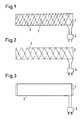
- the liquid lines shown in FIGS. 1 to 3 have a tubular or tubular inside, flexible plastic layer 1, on which a heating wire. 2 is arranged in the form of a resistance wire. at both embodiments is the plastic layer 1 and the heating wire 2 an electrically insulating Volume 3 wound helically. In Figs. 2 and 3, the tape 3 is not shown to show the course of the heating wire 2 to recognize better.
- the insulating tape 3 is an adhesive tape whose adhesive can be bonded with the plastic layer 1.
- the Volume 3 has a side coated with adhesive Fabric strips on, which gives the tape a high tear resistance gives.
- the heating wire is a loop, which is helical as Double helix wound around the plastic layer 1 is.
- FIG. 3 forms the Heating wire 2 a loop, whose forward and return lines however, facing away from each other sides of the plastic layer 1 straight.
- the heating wire 2 is provided with an electrically insulating Cover made of plastic, so that the back and Return lines in the embodiment of FIGS. 1 and 2 can run close together, but one Short circuit is avoided.
- the helical course and the close neighborhood the Schudrahtabitese increases the heat output per Area unit of the plastic layer 1, so that the liquid flowing through the liquid line can be heated quickly.
- the ends of the heating wire 2 are connected to a plug. 4 connected, in turn, with a socket of a Voltage source can be plugged together.
- the formation of the insulating tape 3 as a tape simplifies the production of the liquid line in the Compared to a known fluid line, at which vulcanized the insulating tape to the plastic layer 1 is.
- the wrapping of the plastic layer 1 with the tape is very easy and quick to carry out. A subsequent vulcanization is eliminated.
Landscapes
- Engineering & Computer Science (AREA)
- General Engineering & Computer Science (AREA)
- Mechanical Engineering (AREA)
- Chemical & Material Sciences (AREA)
- Combustion & Propulsion (AREA)
- Chemical Kinetics & Catalysis (AREA)
- Health & Medical Sciences (AREA)
- Toxicology (AREA)
- Resistance Heating (AREA)
- Pipe Accessories (AREA)
- Instantaneous Water Boilers, Portable Hot-Water Supply Apparatuses, And Control Of Portable Hot-Water Supply Apparatuses (AREA)
Abstract
Description
- Fig. 1
- eine Seitenansicht eines ersten Ausführungsbeispiels einer erfindungsgemäßen elektrisch beheizbaren Flüssigkeitsleitung,
- Fig. 2
- eine Seitenansicht der Flüssigkeitsleitung nach Fig. 1 ohne das gemäß Fig. 2 außen herumgewickelte Klebeband,
- Fig. 3
- eine Seitenansicht eines zweiten Ausführungsbeispiels einer erfindungsgemäßen Flüssigkeitsleitung, bei dem zur Verdeutlichung ebenfalls das erfindungsgemäß vorgesehene Klebeband weggelassen ist.
Claims (6)
- Elektrisch beheizbare Flüssigkeitsleitung, bei der auf einer inneren Kunststoffschicht (1) ein Heizdraht (2) angeordnet und um die Kunststoffschicht (1) und den Heizdraht (2) ein elektrisch isolierendes Band (3) wendelförmig herumgewickelt ist, dadurch gekennzeichnet, daß das isolierende Band (3) ein Klebeband ist, dessen Klebstoff mit der Kunststoffschicht (1) verklebbar ist.
- Flüssigkeitsleitung nach Anspruch 1, dadurch gekennzeichnet, daß das Klebeband einen einseitig mit Klebstoff beschichteten Textilstreifen aufweist.
- Flüssigkeitsleitung nach Anspruch 1 oder 2, dadurch gekennzeichnet, daß der Heizdraht (2) wendelförmig um die Kunststoffschicht (1) herumgewickelt ist.
- Flüssigkeitsleitung nach einem der Ansprüche 1 bis 3, dadurch gekennzeichnet, daß der Heizdraht (2) in Form einer Doppelwendel um die Kunststoffschicht (1) herumgewickelt ist und einen elektrisch isolierenden Überzug aufweist.
- Flüssigkeitsleitung nach einem der Ansprüche 1 bis 4, dadurch gekennzeichnet, daß der Heizdraht (2) eine Schlaufe bildet.
- Flüssigkeitsleitung nach Anspruch 4 oder 5, dadurch gekennzeichnet, daß die Enden des Heizdrahtes (2) mit einem Stecker (4) verbunden sind.
Applications Claiming Priority (2)
| Application Number | Priority Date | Filing Date | Title |
|---|---|---|---|
| DE10344137A DE10344137A1 (de) | 2003-09-24 | 2003-09-24 | Elektrisch beheizbare Flüssigkeitsleitung |
| DE10344137 | 2003-09-24 |
Publications (2)
| Publication Number | Publication Date |
|---|---|
| EP1519098A1 true EP1519098A1 (de) | 2005-03-30 |
| EP1519098B1 EP1519098B1 (de) | 2006-09-06 |
Family
ID=34177911
Family Applications (1)
| Application Number | Title | Priority Date | Filing Date |
|---|---|---|---|
| EP04017169A Revoked EP1519098B1 (de) | 2003-09-24 | 2004-07-21 | Elektrisch beheizbare Flüssigkeitsleitung |
Country Status (7)
| Country | Link |
|---|---|
| US (1) | US6996337B2 (de) |
| EP (1) | EP1519098B1 (de) |
| JP (1) | JP2005098689A (de) |
| KR (1) | KR20050030146A (de) |
| CA (1) | CA2482302A1 (de) |
| DE (2) | DE10344137A1 (de) |
| ES (1) | ES2268548T3 (de) |
Cited By (4)
| Publication number | Priority date | Publication date | Assignee | Title |
|---|---|---|---|---|
| EP2418364A1 (de) * | 2007-03-27 | 2012-02-15 | Veritas Ag | Beheizbare Leitung |
| WO2013026560A1 (de) * | 2011-08-19 | 2013-02-28 | Voss Automotive Gmbh | Schlauch und verfahren zu seiner herstellung |
| JP2013535625A (ja) * | 2010-07-23 | 2013-09-12 | フォス・アウトモーティヴ・ゲー・エム・ベー・ハー | 加熱可能な媒体パイプ |
| US9103481B2 (en) | 2010-07-23 | 2015-08-11 | Voss Automotive Gmbh | Heatable medium pipe and method for producing same |
Families Citing this family (30)
| Publication number | Priority date | Publication date | Assignee | Title |
|---|---|---|---|---|
| US20070036528A1 (en) * | 2005-07-29 | 2007-02-15 | William Ferrone | Heated hose electrical cord |
| DE102005037201A1 (de) * | 2005-08-06 | 2007-02-22 | Eichenauer Heizelemente Gmbh & Co. Kg | Heizsystem |
| ATE422022T1 (de) * | 2005-09-16 | 2009-02-15 | Dayco Fluid Technologies Spa | Vorrichtung zur reinigung von abgasen eines fahrzeugs durch gezielte katalytische reduktion mit einer beheizten rohrleitung |
| EP1931905B1 (de) * | 2005-09-16 | 2012-08-08 | DYTECH - Dynamic Fluid Technologies S.p.A. | Mehrlagige rohrleitung zum transportieren und erhitzen eines fluids |
| DE202007019332U1 (de) | 2007-03-27 | 2011-11-15 | Veritas Ag | Beheizbare Leitung |
| DE202008003365U1 (de) | 2008-03-10 | 2009-07-16 | Voss Automotive Gmbh | Beheizbare Fluidleitung |
| US20080298788A1 (en) * | 2007-06-04 | 2008-12-04 | Teleflex Fluid Systems, Inc. | Heated hose apparatus and method |
| EP2242644A1 (de) * | 2008-01-30 | 2010-10-27 | DYTECH - Dynamic Fluid Technologies S.p.A. | Mehrschichtiger schlauch zur beförderung einer harnstoff enthaltenden wässrigen lösung |
| US8455784B2 (en) * | 2008-05-07 | 2013-06-04 | GM Global Technology Operations LLC | Method and system for welding workpieces |
| DE202008007392U1 (de) | 2008-06-03 | 2009-10-29 | Voss Automotive Gmbh | Fluidleitung und Leitungsverbinder zum Führen und Beheizen eines Mediums |
| DE202008014893U1 (de) | 2008-11-10 | 2010-04-15 | Rehau Ag + Co | Thermisch isolierte, beheizbare und flexible Fluidleitung |
| DE102009022995A1 (de) * | 2009-05-28 | 2010-12-02 | Rehau Ag + Co. | Beheizbare Leitung, insbesondere für ein Kraftfahrzeug zum Transport einer Harnstoff-Wasser-Lösung |
| DE202009012185U1 (de) | 2009-09-08 | 2011-01-27 | Voss Automotive Gmbh | Elektrisch beheizbare Medienleitung |
| ES2409116T3 (es) * | 2010-09-23 | 2013-06-25 | Andreas Massold | Procedimiento para la medición de temperatura en un vehículo. |
| DE102012002411A1 (de) | 2011-02-10 | 2012-10-18 | Voss Automotive Gmbh | Beheizbare Medienleitung |
| US20120275773A1 (en) * | 2011-04-26 | 2012-11-01 | Floyd Ryan A | Reductant Heater |
| WO2013004692A1 (en) * | 2011-07-07 | 2013-01-10 | Nv Bekaert Sa | Selective catalytic reduction tank with heating element |
| BE1020058A3 (nl) * | 2011-07-07 | 2013-04-02 | Bekaert Sa Nv | Tank voor selectieve catalytische reductie met een verwarmingselement. |
| US9428995B2 (en) * | 2013-12-09 | 2016-08-30 | Freedom Oilfield Services, Inc. | Multi-channel conduit and method for heating a fluid |
| CN104727992B (zh) * | 2015-04-01 | 2017-06-13 | 孙伟 | 机动车燃料加热装置 |
| JP6738617B2 (ja) * | 2016-02-26 | 2020-08-12 | 株式会社フジキン | サーマルアクチュエータ、サーマルバルブ、およびマスフローコントローラ |
| EP3497359B1 (de) | 2016-08-15 | 2020-10-07 | Parker-Hannifin Corporation | Umhüllte schlauchheizungsanordnung mit heisstaschenkonfiguration |
| US10396500B2 (en) | 2016-08-31 | 2019-08-27 | Norma U.S. Holding Llc | Electrically conductive conduit assembly |
| KR101845064B1 (ko) * | 2016-10-25 | 2018-05-18 | 한국전력기술 주식회사 | 비방향성 직렬연결 커넥터를 이용한 휴대용 플랜트 계측기 동파방지 장치 |
| DE102019131556A1 (de) * | 2019-11-22 | 2021-05-27 | Eberspächer Exhaust Technology GmbH | Abgasheizer |
| DE102020110869A1 (de) * | 2020-04-22 | 2021-10-28 | Purem GmbH | Abgasheizer |
| CN111616420A (zh) * | 2020-07-17 | 2020-09-04 | 惠州市沛格斯科技有限公司 | 发热模组及发烟设备 |
| DE102020212849A1 (de) | 2020-10-12 | 2022-04-14 | Vitesco Technologies GmbH | Verfahren zur Ermittlung einer Leitungslänge |
| AU2022276359A1 (en) | 2021-05-21 | 2023-12-07 | Elaflex Hiby Gmbh & Co. Kg | Dispensing system with for delivering an operating fluid |
| TWI834188B (zh) * | 2021-06-09 | 2024-03-01 | 美商瓦特洛威電子製造公司 | 冷導管絕緣裝置 |
Citations (5)
| Publication number | Priority date | Publication date | Assignee | Title |
|---|---|---|---|---|
| DE1675407A1 (de) * | 1968-02-03 | 1971-01-21 | Western Packing And Supply Co | Leitungsrohr aus Kunststoff |
| DE2813824A1 (de) * | 1978-03-31 | 1979-10-04 | Kabel Metallwerke Ghh | Waermeisoliertes leitungsrohr bzw. temperierbares rohrbuendelkabel |
| DE19728942A1 (de) * | 1997-07-07 | 1999-01-14 | Brugg Rohrsysteme Gmbh | Elektrisch beheizbares Leitungsrohr sowie Verfahren zu seiner Herstellung |
| EP1125810A1 (de) * | 2000-02-18 | 2001-08-22 | Continental Teves AG & Co. oHG | Beheizbare Rohrleitung für eine hydraulische Bremsvorrichtung |
| EP1329660A2 (de) * | 2002-01-19 | 2003-07-23 | ContiTech Schlauch GmbH | Flexibler, mehrschichtiger, beheizbarer Schlauch |
Family Cites Families (6)
| Publication number | Priority date | Publication date | Assignee | Title |
|---|---|---|---|---|
| FR925461A (fr) * | 1945-08-27 | 1947-09-04 | Dispositif électrique pour empêcher le gel dans les conduites de liquides, notamment dans les conduites d'eau | |
| US4455474A (en) * | 1981-11-27 | 1984-06-19 | Nordson Corporation | Thermally insulated electrically heated hose for transmitting hot liquids |
| DE8713072U1 (de) * | 1987-09-29 | 1989-01-26 | Verwaltungsgesellschaft Geiger Plastic GmbH & Co KG, 8100 Garmisch-Partenkirchen | Schlauch aus Kunststoff zur Führung flüssiger oder gasförmiger Medien mit einem eingebetteten Heizleiter |
| US5381511A (en) | 1993-06-02 | 1995-01-10 | W. L. Gore & Associates, Inc. | Flexible electrically heatable hose |
| DE10107570A1 (de) * | 2001-02-17 | 2002-09-05 | Peter Boettcher | Textiles Klebeband und Verfahren zu seiner Herstellung |
| US6738566B2 (en) * | 2001-07-03 | 2004-05-18 | Nordson Corporation | Insulated hose for transmitting hot liquids |
-
2003
- 2003-09-24 DE DE10344137A patent/DE10344137A1/de not_active Withdrawn
-
2004
- 2004-07-21 EP EP04017169A patent/EP1519098B1/de not_active Revoked
- 2004-07-21 DE DE502004001396T patent/DE502004001396D1/de not_active Revoked
- 2004-07-21 ES ES04017169T patent/ES2268548T3/es not_active Expired - Lifetime
- 2004-09-22 JP JP2004275099A patent/JP2005098689A/ja not_active Abandoned
- 2004-09-23 CA CA002482302A patent/CA2482302A1/en not_active Abandoned
- 2004-09-23 KR KR1020040076345A patent/KR20050030146A/ko not_active Withdrawn
- 2004-09-24 US US10/949,008 patent/US6996337B2/en not_active Expired - Lifetime
Patent Citations (5)
| Publication number | Priority date | Publication date | Assignee | Title |
|---|---|---|---|---|
| DE1675407A1 (de) * | 1968-02-03 | 1971-01-21 | Western Packing And Supply Co | Leitungsrohr aus Kunststoff |
| DE2813824A1 (de) * | 1978-03-31 | 1979-10-04 | Kabel Metallwerke Ghh | Waermeisoliertes leitungsrohr bzw. temperierbares rohrbuendelkabel |
| DE19728942A1 (de) * | 1997-07-07 | 1999-01-14 | Brugg Rohrsysteme Gmbh | Elektrisch beheizbares Leitungsrohr sowie Verfahren zu seiner Herstellung |
| EP1125810A1 (de) * | 2000-02-18 | 2001-08-22 | Continental Teves AG & Co. oHG | Beheizbare Rohrleitung für eine hydraulische Bremsvorrichtung |
| EP1329660A2 (de) * | 2002-01-19 | 2003-07-23 | ContiTech Schlauch GmbH | Flexibler, mehrschichtiger, beheizbarer Schlauch |
Cited By (5)
| Publication number | Priority date | Publication date | Assignee | Title |
|---|---|---|---|---|
| EP2418364A1 (de) * | 2007-03-27 | 2012-02-15 | Veritas Ag | Beheizbare Leitung |
| JP2013535625A (ja) * | 2010-07-23 | 2013-09-12 | フォス・アウトモーティヴ・ゲー・エム・ベー・ハー | 加熱可能な媒体パイプ |
| US9103481B2 (en) | 2010-07-23 | 2015-08-11 | Voss Automotive Gmbh | Heatable medium pipe and method for producing same |
| US9303805B2 (en) | 2010-07-23 | 2016-04-05 | Voss Automotive Gmbh | Heatable medium pipe |
| WO2013026560A1 (de) * | 2011-08-19 | 2013-02-28 | Voss Automotive Gmbh | Schlauch und verfahren zu seiner herstellung |
Also Published As
| Publication number | Publication date |
|---|---|
| KR20050030146A (ko) | 2005-03-29 |
| US20050063689A1 (en) | 2005-03-24 |
| US6996337B2 (en) | 2006-02-07 |
| JP2005098689A (ja) | 2005-04-14 |
| CA2482302A1 (en) | 2005-03-24 |
| EP1519098B1 (de) | 2006-09-06 |
| ES2268548T3 (es) | 2007-03-16 |
| DE502004001396D1 (de) | 2006-10-19 |
| DE10344137A1 (de) | 2005-05-04 |
Similar Documents
| Publication | Publication Date | Title |
|---|---|---|
| EP1519098A1 (de) | Elektrisch beheizbare Flüssigkeitsleitung | |
| EP1818588B1 (de) | Schlauchbaugruppe und Verfahren zu deren Herstellung | |
| EP3276243B2 (de) | Kraftfahrzeug-fluidleitung | |
| DE102010032189A1 (de) | Beheizbare Medienleitung und Verfahren zu deren Herstellung | |
| DE102013000588A1 (de) | Konfektionierte beheizbare Medienleitung, Verwendung einer solchen sowie Verfahren zum Herstellen einer solchen | |
| DE102011120357A1 (de) | Konfektionierte beheizbare Medienleitung mit einer Medienleitung mit zumindest zwei auf deren Außenseite angeordneten Heizelementen und Verfahren zu ihrer Herstellung | |
| EP2653765A1 (de) | Rohrleitung für ein zu temperierendes fluides Medium | |
| EP2201229B1 (de) | Verfahren zur herstellung eines systems zum leiten und temperieren einer harnstoff-wasser-lösung und vorrichtung zur durchführung des verfahrens | |
| WO2018095838A1 (de) | Vorrichtung zur verdampfung eines fluids | |
| DE102012002411A1 (de) | Beheizbare Medienleitung | |
| EP2652382B1 (de) | Beheizbare anschlussvorrichtung für medienführende, elektrisch beheizbare schläuche | |
| EP2666985B1 (de) | Beheizbare Medienleitung | |
| DE202008007392U1 (de) | Fluidleitung und Leitungsverbinder zum Führen und Beheizen eines Mediums | |
| DE20320585U1 (de) | Elektrisch beheizbare Flüssigkeitsleitung | |
| DE202004018697U1 (de) | Schlauch | |
| DE102005023398A1 (de) | Abgasanlage für ein Kraftfahrzeug | |
| EP1770251B1 (de) | Beheizbarer Schlauchleitungsmodul für Abgasnachbehandlungsanlagen von Brennkraftmaschinen | |
| DE102009039972A1 (de) | Mehrkanalschlauch | |
| DE2042183A1 (de) | Biegsame Stroemungsmittelleitung | |
| EP1764541A1 (de) | Elektrische Heizvorrichtung, beheizbarer Schlauch und Herstellungsverfahren derselben | |
| DE102014108499A1 (de) | Beheizbare Fluidleitung | |
| DE4026254A1 (de) | Beheizbarer schlauch, insbesondere fuer scheibenwaschanlagen | |
| DE202013101265U1 (de) | Medienleitung | |
| WO2008145367A1 (de) | Verfahren und anordnung zum erwärmen eines mediums in einem lang gestreckten behältnis, insbesondere in einer schlauchförmigen flüssigkeitszuleitung | |
| DE19616354C2 (de) | Rohrleitungsstück mit elektrischer Leitung |
Legal Events
| Date | Code | Title | Description |
|---|---|---|---|
| PUAI | Public reference made under article 153(3) epc to a published international application that has entered the european phase |
Free format text: ORIGINAL CODE: 0009012 |
|
| 17P | Request for examination filed |
Effective date: 20041208 |
|
| AK | Designated contracting states |
Kind code of ref document: A1 Designated state(s): AT BE BG CH CY CZ DE DK EE ES FI FR GB GR HU IE IT LI LU MC NL PL PT RO SE SI SK TR |
|
| AX | Request for extension of the european patent |
Extension state: AL HR LT LV MK |
|
| 17Q | First examination report despatched |
Effective date: 20050506 |
|
| AKX | Designation fees paid |
Designated state(s): DE ES FR IT |
|
| GRAP | Despatch of communication of intention to grant a patent |
Free format text: ORIGINAL CODE: EPIDOSNIGR1 |
|
| GRAS | Grant fee paid |
Free format text: ORIGINAL CODE: EPIDOSNIGR3 |
|
| GRAA | (expected) grant |
Free format text: ORIGINAL CODE: 0009210 |
|
| AK | Designated contracting states |
Kind code of ref document: B1 Designated state(s): DE ES FR IT |
|
| PG25 | Lapsed in a contracting state [announced via postgrant information from national office to epo] |
Ref country code: IT Free format text: LAPSE BECAUSE OF FAILURE TO SUBMIT A TRANSLATION OF THE DESCRIPTION OR TO PAY THE FEE WITHIN THE PRESCRIBED TIME-LIMIT;WARNING: LAPSES OF ITALIAN PATENTS WITH EFFECTIVE DATE BEFORE 2007 MAY HAVE OCCURRED AT ANY TIME BEFORE 2007. THE CORRECT EFFECTIVE DATE MAY BE DIFFERENT FROM THE ONE RECORDED. Effective date: 20060906 |
|
| REF | Corresponds to: |
Ref document number: 502004001396 Country of ref document: DE Date of ref document: 20061019 Kind code of ref document: P |
|
| REG | Reference to a national code |
Ref country code: ES Ref legal event code: FG2A Ref document number: 2268548 Country of ref document: ES Kind code of ref document: T3 |
|
| ET | Fr: translation filed | ||
| PLBI | Opposition filed |
Free format text: ORIGINAL CODE: 0009260 |
|
| PLAX | Notice of opposition and request to file observation + time limit sent |
Free format text: ORIGINAL CODE: EPIDOSNOBS2 |
|
| 26 | Opposition filed |
Opponent name: VOSS AUTOMOTIVE GMBH Effective date: 20070606 Opponent name: REHAU AG & CO. Effective date: 20070605 |
|
| RAP2 | Party data changed (patent owner data changed or rights of a patent transferred) |
Owner name: NORMA GERMANY GMBH |
|
| PLBB | Reply of patent proprietor to notice(s) of opposition received |
Free format text: ORIGINAL CODE: EPIDOSNOBS3 |
|
| PGFP | Annual fee paid to national office [announced via postgrant information from national office to epo] |
Ref country code: DE Payment date: 20080716 Year of fee payment: 5 Ref country code: ES Payment date: 20080723 Year of fee payment: 5 |
|
| PGFP | Annual fee paid to national office [announced via postgrant information from national office to epo] |
Ref country code: FR Payment date: 20080718 Year of fee payment: 5 Ref country code: IT Payment date: 20080726 Year of fee payment: 5 |
|
| PGRI | Patent reinstated in contracting state [announced from national office to epo] |
Ref country code: IT Effective date: 20081001 |
|
| RDAF | Communication despatched that patent is revoked |
Free format text: ORIGINAL CODE: EPIDOSNREV1 |
|
| RDAG | Patent revoked |
Free format text: ORIGINAL CODE: 0009271 |
|
| STAA | Information on the status of an ep patent application or granted ep patent |
Free format text: STATUS: PATENT REVOKED |
|
| 27W | Patent revoked |
Effective date: 20081125 |