EP1519130A2 - Eiserzeuger für Kühlschränke - Google Patents
Eiserzeuger für Kühlschränke Download PDFInfo
- Publication number
- EP1519130A2 EP1519130A2 EP04007326A EP04007326A EP1519130A2 EP 1519130 A2 EP1519130 A2 EP 1519130A2 EP 04007326 A EP04007326 A EP 04007326A EP 04007326 A EP04007326 A EP 04007326A EP 1519130 A2 EP1519130 A2 EP 1519130A2
- Authority
- EP
- European Patent Office
- Prior art keywords
- icemaker
- ejector
- ice tray
- ice
- sensor
- Prior art date
- Legal status (The legal status is an assumption and is not a legal conclusion. Google has not performed a legal analysis and makes no representation as to the accuracy of the status listed.)
- Granted
Links
- XLYOFNOQVPJJNP-UHFFFAOYSA-N water Substances O XLYOFNOQVPJJNP-UHFFFAOYSA-N 0.000 claims abstract description 41
- 230000004907 flux Effects 0.000 claims description 37
- 238000010438 heat treatment Methods 0.000 claims description 3
- 230000008014 freezing Effects 0.000 description 9
- 238000007710 freezing Methods 0.000 description 9
- 238000000034 method Methods 0.000 description 7
- 238000005192 partition Methods 0.000 description 7
- 235000013305 food Nutrition 0.000 description 6
- 230000008901 benefit Effects 0.000 description 5
- 238000004519 manufacturing process Methods 0.000 description 5
- 238000012986 modification Methods 0.000 description 2
- 230000004048 modification Effects 0.000 description 2
- 241000251468 Actinopterygii Species 0.000 description 1
- 238000005265 energy consumption Methods 0.000 description 1
- 235000013372 meat Nutrition 0.000 description 1
- 239000000155 melt Substances 0.000 description 1
- 230000003252 repetitive effect Effects 0.000 description 1
- 230000002441 reversible effect Effects 0.000 description 1
- 235000013311 vegetables Nutrition 0.000 description 1
- 238000005406 washing Methods 0.000 description 1
Images




Classifications
-
- F—MECHANICAL ENGINEERING; LIGHTING; HEATING; WEAPONS; BLASTING
- F25—REFRIGERATION OR COOLING; COMBINED HEATING AND REFRIGERATION SYSTEMS; HEAT PUMP SYSTEMS; MANUFACTURE OR STORAGE OF ICE; LIQUEFACTION SOLIDIFICATION OF GASES
- F25C—PRODUCING, WORKING OR HANDLING ICE
- F25C1/00—Producing ice
- F25C1/22—Construction of moulds; Filling devices for moulds
- F25C1/24—Construction of moulds; Filling devices for moulds for refrigerators, e.g. freezing trays
-
- F—MECHANICAL ENGINEERING; LIGHTING; HEATING; WEAPONS; BLASTING
- F25—REFRIGERATION OR COOLING; COMBINED HEATING AND REFRIGERATION SYSTEMS; HEAT PUMP SYSTEMS; MANUFACTURE OR STORAGE OF ICE; LIQUEFACTION SOLIDIFICATION OF GASES
- F25C—PRODUCING, WORKING OR HANDLING ICE
- F25C1/00—Producing ice
- F25C1/04—Producing ice by using stationary moulds
-
- F—MECHANICAL ENGINEERING; LIGHTING; HEATING; WEAPONS; BLASTING
- F25—REFRIGERATION OR COOLING; COMBINED HEATING AND REFRIGERATION SYSTEMS; HEAT PUMP SYSTEMS; MANUFACTURE OR STORAGE OF ICE; LIQUEFACTION SOLIDIFICATION OF GASES
- F25C—PRODUCING, WORKING OR HANDLING ICE
- F25C5/00—Working or handling ice
- F25C5/18—Storing ice
- F25C5/182—Ice bins therefor
- F25C5/185—Ice bins therefor with freezing trays
-
- F—MECHANICAL ENGINEERING; LIGHTING; HEATING; WEAPONS; BLASTING
- F25—REFRIGERATION OR COOLING; COMBINED HEATING AND REFRIGERATION SYSTEMS; HEAT PUMP SYSTEMS; MANUFACTURE OR STORAGE OF ICE; LIQUEFACTION SOLIDIFICATION OF GASES
- F25C—PRODUCING, WORKING OR HANDLING ICE
- F25C5/00—Working or handling ice
- F25C5/20—Distributing ice
- F25C5/22—Distributing ice particularly adapted for household refrigerators
-
- F—MECHANICAL ENGINEERING; LIGHTING; HEATING; WEAPONS; BLASTING
- F25—REFRIGERATION OR COOLING; COMBINED HEATING AND REFRIGERATION SYSTEMS; HEAT PUMP SYSTEMS; MANUFACTURE OR STORAGE OF ICE; LIQUEFACTION SOLIDIFICATION OF GASES
- F25C—PRODUCING, WORKING OR HANDLING ICE
- F25C2305/00—Special arrangements or features for working or handling ice
- F25C2305/024—Rotating rake
-
- F—MECHANICAL ENGINEERING; LIGHTING; HEATING; WEAPONS; BLASTING
- F25—REFRIGERATION OR COOLING; COMBINED HEATING AND REFRIGERATION SYSTEMS; HEAT PUMP SYSTEMS; MANUFACTURE OR STORAGE OF ICE; LIQUEFACTION SOLIDIFICATION OF GASES
- F25C—PRODUCING, WORKING OR HANDLING ICE
- F25C2400/00—Auxiliary features or devices for producing, working or handling ice
- F25C2400/10—Refrigerator units
-
- F—MECHANICAL ENGINEERING; LIGHTING; HEATING; WEAPONS; BLASTING
- F25—REFRIGERATION OR COOLING; COMBINED HEATING AND REFRIGERATION SYSTEMS; HEAT PUMP SYSTEMS; MANUFACTURE OR STORAGE OF ICE; LIQUEFACTION SOLIDIFICATION OF GASES
- F25C—PRODUCING, WORKING OR HANDLING ICE
- F25C2500/00—Problems to be solved
- F25C2500/06—Spillage or flooding of water
-
- F—MECHANICAL ENGINEERING; LIGHTING; HEATING; WEAPONS; BLASTING
- F25—REFRIGERATION OR COOLING; COMBINED HEATING AND REFRIGERATION SYSTEMS; HEAT PUMP SYSTEMS; MANUFACTURE OR STORAGE OF ICE; LIQUEFACTION SOLIDIFICATION OF GASES
- F25C—PRODUCING, WORKING OR HANDLING ICE
- F25C2700/00—Sensing or detecting of parameters; Sensors therefor
- F25C2700/06—Rotation angle of the ejector ejecting ice from a stationary mould
Definitions
- the present invention relates to refrigerators, and more particularly, to an icemaker in a refrigerator for making ice automatically.
- the refrigerator is used for long time fresh storage of food.
- the refrigerator has food storage chambers each of which temperature is maintained in a low temperature state by a refrigerating cycle, for fresh storage of the food.
- the refrigerating chamber and the freezing chamber are typical.
- the refrigerating chamber is maintained at about 3°C ⁇ 4°C for long time fresh storage of food and vegetable, and the freezing chamber is maintained at a subzero temperature for long time storage of meat and fish in a frozen state, and making and storage of ice pieces.
- the present invention is directed to an icemaker in a refrigerator that substantially obviates one or more of the problems due to limitations and disadvantages of the related art.
- An object of the present invention is to provide an icemaker in a refrigerator, which makes ice pieces automatically for user's easy and convenient taking out of ice pieces.
- Another object of the present invention is to provide an icemaker of improved structure in a refrigerator, which can prevent splash of water from the icemaker when the door is opened or closed.
- Another object of the present invention is to provide an icemaker of improved structure in a refrigerator, having a structure that can prevent splash of water from an ice tray, in which an ejector that ejects ice pieces from an ice tray is made to be controlled easily by using a simple structure.
- the icemaker in a refrigerator includes an ice tray provided to a door on the refrigerator for holding water, an ejector fitted adjacent to the ice tray so as to be rotatable by a motor for ejecting ice from the ice tray, means for detecting a rotation angle of the ejector, and a control part for controlling a rotation direction of the ejector based on information detected at the means.
- the icemaker further includes a dropper having a sloped surface covering a part of an upper part of the ice tray, and an overflow preventing member opposite to the dropper in the upper part of the ice tray.
- the overflow preventing member is a panel extended upward by a length from the upper part of the ice tray.
- the panel includes a curved surface facing an inside of the ice tray, or the panel is vertical.
- the icemaker further includes a heater for heating the ice tray when the water held in the ice tray is frozen.
- the means includes a magnet fitted to a rotating body rotatably interlocked with a shaft of the motor, and at least two sensors fitted to a plate spaced from each other, the plate being arranged opposite to the rotating body, each for sensing a magnetic flux when the magnet comes close thereto, to measure a rotation angle of the ejector.
- the rotating body is a driven gear rotatably engaged with a driving gear connected to the shaft of the motor, for rotating with the ejector.
- the sensors include a first sensor for sensing an initial position of the ejector before the ejector ejects ice, and a second sensor for sensing a finish position when the ejector ejects the ice fully.
- a distance from a rotation center of the rotating body to the magnet is the same with a distance from a point of the plate opposite to the rotation center to each of the sensors.
- the second sensor is fitted in a range of angle of 170° ⁇ 280° from the first sensor along a rotation direction of the rotating body.
- the control part reverses the ejector when the second sensor senses the flux of the magnet. In this case, it is preferable that the ejector reverses until the first sensor senses the flux of the magnet.
- the control part turns on the heater when water in the ice tray is frozen, and turns off when the second senor senses the flux of the magnet.
- the sensors further include a third sensor fitted between the first sensor and the second sensor.
- a distance from a rotation center of the rotating body to the magnet is the same with a distance from a point of the plate opposite to the rotation center to each of the sensors.
- the third sensor is fitted in a range of angle of 35° ⁇ 145° from the first sensor along a rotation direction of the rotating body.
- the control part turns on the heater when water in the ice tray is frozen, and turns off when the third senor senses the flux of the magnet.
- FIG 1 illustrates a perspective view showing an icemaker 100 and container 200 in accordance with a first preferred embodiment of the present invention.
- the icemaker makes a plurality of ice pieces by using cold air in the freezing chamber, and the container 200 holds the ice pieces made at the icemaker 100. Therefore, once the icemaker 100 and the container 200 of the present invention are provided to the refrigerator, the user can use the ice pieces easily. Structures of the icemaker 100 and the container 200 will be described in more detail with reference to the attached drawings.
- the icemaker 100 is provided to, for an example, a freezing chamber of a refrigerator, and includes an ice tray 110, a water supplying part 120, an ejector 140, and a control box 130.
- the ice tray 110 is semicylindrical with an opened top for storage of water and ice.
- the ice tray 110 has partition ribs 111 which divide an inside space of the ice tray into many small spaces. As shown in FIG. 1, the partition ribs 111 are projected to a radial direction from an inside surface of the ice tray 110.
- the partition ribs 111 makes the ice tray 110 to produce a plurality of ice pieces at a time.
- the water supplying part 120 at one side of the ice tray 110 for supplying water to the ice tray 110.
- brackets 150 in a rear side of the ice tray 110 for fixing the icemaker 100 to the freezing chamber.
- the ejector 140 arranged adjacent to the ice tray 110, includes a shaft 141, and a plurality of fins 145.
- the shaft 141 on an axis of the ejector 140, is arranged over an inside of the ice tray 110 to cross a central part along a length direction thereof.
- the fins 145 extend from an outside circumferential surface of the shaft 141 to a radial direction of the shaft 141. It is preferable that the fins 145 are formed at regular intervals along the length direction of the shaft 141, particularly, one of the fins 145 are arranged to every small space in the ice tray 110 formed by the partition ribs 111.
- control box 130 is mounted at one outside surface of the ice tray 110.
- the control box 130 contains a motor (not shown), a driving gear 132, a driven gear 133, and the like, which will be described in more detail, with reference to FIGS. 2 and 3.
- the driving gear 132 is connected to a shaft 131 of the motor (not shown), and rotated by the motor.
- the driven gear 133 rotatably engaged with the driving gear 132, has the shaft 141 of the ejector 140 connected thereto. Therefore, when the motor is operated, the driving gear 132 and the driven gear 133, engaged with each other, rotate, to rotate the ejector 140, accordingly.
- the driven gear 133 has more teeth than the driving gear 132, for slow ejection of ice from the ice tray 110 with the ejector 140 even if the shaft 131 of the motor rotates at a fast speed.
- the icemaker 100 in accordance with a first preferred embodiment of the present invention, there is a device for detecting a rotation angle of the ejector 140 provided in the control box 130, which will be described with reference to FIGS. 2 and 3.
- FIG. 2 there is a magnet 134 fitted to a surface of a rotating body rotatable interlocked with the shaft 131 of the motor, for an example, the driven gear 133.
- a plate 135 arranged opposite to the rotating body, i.e., the driven gear 133 in the control box 130, additionally.
- the plate 135 has a sensor 136 for sensing a flux of the magnet 134 fitted thereto.
- the plate 135 is stationary and fixed to the control box 130.
- the sensor 136 senses the flux of the magnet 134, such that the control part (not shown) detects a rotation angle of the ejector 140.
- FIG. 1 there are a plurality of droppers 160 in a front part of the ice tray 110, i.e., in an upper part of a side opposite to a side the brackets 150 are fitted thereto.
- the droppers 160 extend from the upper part of front part of the ice tray 110 to a part close to the shaft 141. There are small gaps between adjacent droppers 160, through which the fins 145 pass respectively when the shaft 141 rotates.
- the shaft 141 rotates, the ice in the ice tray 110 is pushed by the fins 145, separated from the ice tray 110, ejected through the opened top of the ice tray 110, and dropped on the droppers 160.
- the ice dropped onto the droppers 160 drops under the icemaker 100, and stored in the container 200 under the icemaker 100.
- the upper surfaces of the droppers 160 guide the ice separated from the ice tray 110 to drop downward, well. Therefore, as shown in FIG. 1, in the present invention, it is preferable that the upper surfaces of the droppers 160 are sloped such that parts adjacent to the shaft 141 are positioned higher than the front side of the ice tray 110.
- a structure for preventing the ice pieces separated from the ice tray 110 by the fins 145 drop in a rear side of the ice tray 110.
- a rear side end of the ice tray 110 is positioned slightly higher than the shaft 141, so that the ice pieces, separated from the ice tray 110 as the ice pieces move to a rear side of the ice tray 110 by the fins 145, are guided to the front side of the ice tray 110, and drop on the upper surfaces of the droppers 160, naturally.
- FIG. 4 there is a heater 170 on an underside of the ice tray 110.
- the heater 170 heats a surface of the ice tray 110 for a short period of time to melt the ice on a surface of the ice tray 110 slightly. Then, the ice pieces in the ice tray 110 are separated easily when the shaft 141 and the fins 145 are rotated.
- the icemaker 100 of the present invention may be provided with a temperature sensor (not shown), additionally.
- the temperature senor is fitted to one side of the ice tray 110, for measuring a surface temperature of the ice tray 110. Therefore, the control part (not shown) can determine if the water supplied to the ice tray 110 is frozen with reference to a surface temperature of the ice tray 110 measured with the temperature sensor.
- the icemaker 100 may not be provided with the temperature senor.
- the control part rotates the ejector 140 after a preset time period is passed after the supply of the water to the ice tray 110.
- the container 200 is arranged under the icemaker 100, and has an open top for receiving and storage of the ice pieces dropped from the icemaker 100.
- the icemaker 100 of the present invention may be provided with a sensing arm 180 for measuring quantity of ice stored in the container 200, additionally.
- the sensing arm 180 moves up/down under the control of the control part (not shown) to measure quantity of ice in the container 200.
- the sensing arm moves down at regular intervals, when a move down distance of the sensing arm 180 is great if the quantity of ice stored in the container 200 is small, and, opposite to this, a move down distance of the sensing arm 180 is small if the quantity of ice stored in the container 200 is much.
- the control part can measures the quantity of ice stored in the container 200 with reference to the move down distance of the sensing arm 180.
- the icemaker 100 can continue or discontinue production of the ice depending on the quantity of the ice stored in the container 200.
- the control part controls the motor to move the ejector 140 to an initial position.
- the initial position is a position (see FIG. 4) at which the fins 145 of the ejector 140 are set standby before the water supplied to the ice tray 110 is frozen.
- the sensing arm 180 When the ejector 140 is positioned at the initial position, the sensing arm 180 is operated. If the control part (not shown) determines that there is shortage of ice in the container 200 as a result of operation of the sensing arm 180, water is supplied to the water supplying part 120 of the icemaker 100.
- the water supplied to the water supplying part 120 is filled in spaces between the partition ribs 111 of the ice tray 110, and frozen by cold air in the freezing chamber. According to this, many pieces of ice each having a fixed size are produced with the partition ribs 111 in the ice tray 110.
- the control part puts the heater 170 into operation.
- full freeze of the water in the ice tray 110 is determined with reference to a surface temperature of the ice tray 110 the temperature sensor measured, or pass of a preset time period.
- the ice on the surface of the ice tray 110 melts slightly, and separated from the ice tray 110. Then, as the motor is operated, the shaft 141 and the fins 145 are rotated.
- the fins 145 push the ice pieces between the partition ribs 111 in a circumferential direction of the ice tray 110, such that the ice pieces, separated from the ice tray fully by the fins 145, are ejected through the open top of the ice tray 110, and drop onto the droppers 160.
- the ice pieces dropped onto the droppers 160 move along the sloped upper surface of the droppers 160, until the ice pieces drops down to the container 200 under the icemaker 100.
- the driven gear 133 keeps rotating in a clockwise direction in FIG. 4 together with the ejector 140.
- the sensor 136 senses a flux of the magnet 134. Then, determining that the ice pieces are ejected fully, the control part rotates the ejector 140 only to the initial position, and stops the ejector 140.
- the sensing arm 180 senses quantity of the ice in the container 200. If it is determined that there is shortage of ice still with the sensing arm 180, above process is repeated, to keep production of ice pieces, until a certain amount of ice pieces are filled in the container 200 when the control part stops production of the ice with reference to the quantity of ice sensed by the sensing arm 180.
- the icemaker 100 and the container 200 are provided to the freezing chamber of the refrigerator. Therefore, since the icemaker 100 and the container 200 occupy much of a volume of the freezing chamber, a space of the refrigerator can not be used, effectively.
- the present invention suggests an icemaker of an improved structure which can prevent the splash of the water from the ice tray when the door is opened or closed, which will be described.
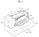
- FIG. 5 illustrates an icemaker 100 and a container 200 in accordance with a second preferred embodiment of the present invention.
- structures of the icemaker 100 and the container 200 are similar to ones described with reference to FIG. 1. Therefore, the second embodiment will be described putting emphasis on characters of the second embodiment distinctive from the first embodiment hereafter. In describing the second embodiment, parts the same with the first embodiment will be given the same names and reference symbols.
- the icemaker 100 in accordance with a second preferred embodiment of the present invention is also provided with a dropper 165 of an improved structure that can prevent the splash of water, and having an overflow preventing member 190.
- the overflow preventing member 190 and the dropper 165 are provided opposite to each other in an upper part of the ice tray 110 for preventing splash of water from the ice tray 110 when the door on the refrigerator is opened or closed.
- the dropper 165 covers a part of an upper part of the ice tray 110. That is, the dropper 165 is not provided with gaps for passing the fins 145 of the ejector 140. Therefore, even if water washes inside of the ice tray 110, the water does not splash over in the dropper side 165.
- the overflow preventing member 190 is arranged opposite to the dropper 165 in the upper part of the ice tray 110.
- the overflow preventing member 190 may have a form of a panel extended upward by a length from the upper part of the ice tray.
- the panel may be curved or flat.
- the panel When the panel is curved, it is preferable that a surface facing an inside of the ice tray 110 is curved. Then, the water washing inside of the ice tray 110 is guided into the ice tray 110 after moving along the curved surface of the panel.
- the panel is flat, it is preferable that the panel stands vertical in the upper part of the ice tray 110.
- the overflow panel 190 is vertical, the ice tray 110 and the overflow preventing member 190 can be fabricated as one unit easily by using one mold.
- the overflow preventing member 190 and the dropper 165 without gap provided to the icemaker 100 in accordance with the second preferred embodiment of the present invention can prevent splash of water to an outside of the icemaker 100. According to this, the icemaker 100 and the container 200 can be mounted on the door of the refrigerator, thereby permitting effective use of the inside space of the refrigerator.
- the second embodiment of the present invention provides a structure which reverses the ejector 140 once the ejector 140 rotates to a position at which the ice is ejected fully.
- the icemaker 100 in accordance with the second embodiment of the present invention includes means for detecting a rotation angle of the ejector 140, and a control part for controlling a rotation direction of the ejector with reference to information detected at the means.
- the means includes a magnet 134, and at least two sensors for sensing a flux of the magnet 134 at positions different from each other, which will be described in detail with reference to the attached drawings.
- the magnet 134 is fitted to a rotating body rotatably interlocked with a shaft 131 of a motor (not shown).
- the rotating body is fabricated separately and provided in the control box 130, for making the structure simple, and the box 130 compact, it is preferable that the magnet 134 is fitted to the driven gear 133.
- the driven gear 133 engaged with the driving gear 132 connected to the shaft 131 of the motor, rotates with the ejector 140.
- the sensors are fitted to a plate 135, so that the sensors sense a flux when the magnet 134 comes close thereto.
- the plate 135 is arranged opposite to the rotating body, i.e., the driven gear 133, and the sensor are fitted to the plate 135 spaced from each other.
- the first sensor senses the initial position before the ejector 140 ejects ice
- the second sensor 138 senses a finish position at which the ejector 140 ejects ice, fully.
- the first sensor 137 and the second sensor 138 sense the flux accurately when the magnet 134 comes close thereto, respectively.
- a distance from a rotation center of the rotating body, i.e., the driven gear 133 to the magnet 134 is the same with a distance from one point of the plate 135 opposite to the rotation center of the driven gear 133 to the first sensor 137 or the second sensor 138.
- the second senor 138 is arranged within a range of angle of approx. 170° ⁇ 280° from the first sensor 137 depending on a rotation direction of the rotating body, i.e., the driven gear 133. Because the ice pieces is ejected from the ice tray 110 fully when the fins 145 of the ejector 140 rotates to above range of angle.
- the control part determines that the ejector 140 ejects the ice fully when the second sensor 138 senses a flux after the ejector 140 is rotated. Therefore, the control part reverses the ejector 140 when the second sensor 138 senses the flux.
- the motor of the second embodiment is reversible.
- the control part determines that the ejector 140 is at the initial position. According to this, the control part stops the ejector 140 when the first sensor 137 senses the magnetic flux after the ejector 140 reverses.
- the icemaker 100 in accordance with the second embodiment of the present invention can control the ejector 140 easily only by using very simple structure.
- the control part turns on the heater 170 when water in the ice tray 110 is frozen, and turns off the heater 170 when the second sensor 138 senses the flux of the magnet.
- a heating time period of the heater 170 can be reduced, not only to reduce power consumption, but also to prevent temperature rise of the freezing chamber by the heater 170.
- the plate 135 is provided with a third sensor 139 in addition to the first sensor 137 and the second sensor 138. Both the first sensor 137 and the second sensor 138 have the same positions and services with the first embodiment.
- the heater 170 turns off when the third sensor 139 senses the flux.
- a distance from a rotation center of the driven gear 133 to the magnet 134 is the same with a distance from one point on the plate 135 opposite to the rotation center of the driven gear 133 to the third sensor 139.
- the third sensor 139 is arranged between the first sensor 137 and the second sensor 138.
- the third sensor 139 is arranged in a range of angle of approx. 35° ⁇ 145° from the first sensor 137, depending on a rotation direction of the rotating body, i.e., the driven gear 133.
- the control part turns of the heater 170.
- the control part determining that the ice is ejected fully, reverses the ejector 140.
- the control part determining that the ejector 140 is at the initial position, stops the ejector 140.
- the icemaker 100 can turn off the heater 170 earlier than a case when the icemaker 100 has two sensors.
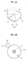
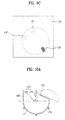
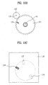
- the ejector 140 When power is provided to the icemaker 100, the ejector 140 is set at the initial position. In this instance, since a position the first sensor 137 senses the flux is the initial position, the control part can position the ejector 140 at the initial position, accurately. Positions of the fins 145, the magnet 134, and the sensors 137, 139, and 139 in a state the ejector 140 is at the initial position are shown well in FIGS. 8A - 8C.
- the control part puts the heater 170 into operation.
- a surface temperature of the ice tray 110 rises as the heater 170 is operated, to separate the ice from the ice tray 110.
- the control part puts the motor into operation, to rotate the ejector 140. Then, as the driven gear 133 rotates, a position of the magnet 134 also changes. The ejector 140 rotates until the magnet 134 comes to a position opposite to the third sensor139. In this instance, positions of the fins 145, the magnet 134, and the sensors 137, 138, and 139 are illustrated in FIGS. 9A ⁇ 9C, well. When the third sensor 139 senses the flux, the control part turns off the heater 170.
- the ejector 140 keeps rotating. Accordingly, after a short time period, the magnet 134 faces the second sensor 138. In this instance, positions of the fins 145, the magnet 134, and the sensors 137, 138, and 139 are illustrated in FIGS. 10A ⁇ 10C, well.
- the control part determining that the ice is ejected fully, reverses the ejector 140.
- the control part determining that the ejector 140 is at the initial position, stops the ejector 140.
- the structure of the present invention has the following advantages.
- the automatic ejection of the many pieces of ice produced at the ice tray permits the user to take out ice pieces from the container any time with convenience and easy without giving an effort of separating the ice from the ice tray.
- the dropper with the overflow preventing member and without the gaps provided to the ice tray can prevent splash of water in opening or closing of the door on the refrigerator.
- the icemaker can be mounted on the door on the refrigerator, and an inside space of the refrigerator can be used, effectively.
- the ejector and the heater can be operated effectively, even with a simple structure having at least two sensors and one magnet.
- An operation time period of the heater can be shortened, to reduce an energy consumption.
Landscapes
- Engineering & Computer Science (AREA)
- Physics & Mathematics (AREA)
- Mechanical Engineering (AREA)
- Thermal Sciences (AREA)
- General Engineering & Computer Science (AREA)
- Production, Working, Storing, Or Distribution Of Ice (AREA)
Applications Claiming Priority (2)
| Application Number | Priority Date | Filing Date | Title |
|---|---|---|---|
| KR2003066598 | 2003-09-25 | ||
| KR1020030066598A KR100565624B1 (ko) | 2003-09-25 | 2003-09-25 | 자동제빙기용 이젝터의 회전 제어장치 |
Publications (3)
| Publication Number | Publication Date |
|---|---|
| EP1519130A2 true EP1519130A2 (de) | 2005-03-30 |
| EP1519130A3 EP1519130A3 (de) | 2005-04-06 |
| EP1519130B1 EP1519130B1 (de) | 2012-12-19 |
Family
ID=34192268
Family Applications (1)
| Application Number | Title | Priority Date | Filing Date |
|---|---|---|---|
| EP04007326A Expired - Lifetime EP1519130B1 (de) | 2003-09-25 | 2004-03-26 | Eiserzeuger für Kühlschränke |
Country Status (4)
| Country | Link |
|---|---|
| US (1) | US7051541B2 (de) |
| EP (1) | EP1519130B1 (de) |
| KR (1) | KR100565624B1 (de) |
| CN (1) | CN1289886C (de) |
Cited By (3)
| Publication number | Priority date | Publication date | Assignee | Title |
|---|---|---|---|---|
| CN102620495A (zh) * | 2012-04-06 | 2012-08-01 | 浙江大学 | 一种制冰控制方法及制冰系统 |
| EP2910876A3 (de) * | 2014-02-24 | 2015-12-23 | LG Electronics Inc. | Eisherstellungsvorrichtung, Kühlschrank mit der Eisherstellungsvorrichtung und Verfahren zur Steuerung des Kühlschranks |
| KR20200057598A (ko) * | 2018-11-16 | 2020-05-26 | 엘지전자 주식회사 | 아이스 메이커 및 냉장고 |
Families Citing this family (48)
| Publication number | Priority date | Publication date | Assignee | Title |
|---|---|---|---|---|
| KR100671567B1 (ko) * | 2004-05-18 | 2007-01-18 | 엘지전자 주식회사 | 냉장고용 제빙기의 만빙 감지 장치 |
| KR100642362B1 (ko) * | 2004-11-02 | 2006-11-03 | 엘지전자 주식회사 | 제빙기의 급수량 제어장치 및 제어방법 |
| KR100690671B1 (ko) * | 2005-03-11 | 2007-03-09 | 엘지전자 주식회사 | 냉장고의 아이스빈 |
| KR100748520B1 (ko) * | 2005-03-14 | 2007-08-13 | 엘지전자 주식회사 | 개방형 아이스빈의 셔터 개폐구조 |
| US7631513B2 (en) * | 2005-03-25 | 2009-12-15 | Lg Electronics Inc. | Ice bank of refrigerator |
| US7707847B2 (en) * | 2005-11-30 | 2010-05-04 | General Electric Company | Ice-dispensing assembly mounted within a refrigerator compartment |
| KR100786075B1 (ko) * | 2005-12-16 | 2007-12-17 | 엘지전자 주식회사 | 냉장고의 운전 제어 방법 |
| KR100808171B1 (ko) * | 2005-12-16 | 2008-03-03 | 엘지전자 주식회사 | 제빙장치 및 그 제어방법 |
| KR100755840B1 (ko) * | 2005-12-16 | 2007-09-07 | 엘지전자 주식회사 | 제빙 장치와 이를 이용한 제빙 방법 |
| KR20090007923A (ko) * | 2007-07-16 | 2009-01-21 | 엘지전자 주식회사 | 제빙트레이 |
| KR101535481B1 (ko) * | 2008-04-15 | 2015-07-09 | 엘지전자 주식회사 | 냉장고 제빙기의 만빙 감지 장치 |
| KR101456571B1 (ko) * | 2008-05-01 | 2014-10-31 | 엘지전자 주식회사 | 냉장고 제빙기의 만빙 감지 장치 및 그 만빙 감지 방법 |
| KR101535484B1 (ko) | 2008-04-15 | 2015-07-09 | 엘지전자 주식회사 | 냉장고 제빙기의 만빙 감지 장치 |
| KR101456572B1 (ko) * | 2008-05-27 | 2014-10-31 | 엘지전자 주식회사 | 냉장고 제빙기의 만빙 감지 장치의 센서 히터 제어 방법 |
| KR101535482B1 (ko) * | 2008-04-15 | 2015-07-09 | 엘지전자 주식회사 | 냉장고 제빙기의 만빙 감지 장치 |
| US20100139299A1 (en) * | 2008-04-15 | 2010-06-10 | Dong-Hoon Lee | Refrigerator and full ice level sensing apparatus thereof |
| WO2010016629A1 (en) * | 2008-08-04 | 2010-02-11 | Lg Electronics Inc. | Ice maker and refrigerator having the same |
| CN102242997B (zh) * | 2010-05-14 | 2015-03-18 | 海尔集团公司 | 冰箱门体制冰机 |
| US8813509B2 (en) | 2011-06-02 | 2014-08-26 | General Electric Company | Ice making assembly with optimized harvesting and related refrigeration appliance |
| KR101326110B1 (ko) * | 2011-09-02 | 2013-11-06 | 주식회사 대창 | 제빙기 |
| CN102494452B (zh) * | 2011-12-08 | 2014-03-12 | 合肥美的电冰箱有限公司 | 用于冰箱的制冰机及具有它的冰箱 |
| US9587871B2 (en) | 2012-05-03 | 2017-03-07 | Whirlpool Corporation | Heater-less ice maker assembly with a twistable tray |
| US9513045B2 (en) | 2012-05-03 | 2016-12-06 | Whirlpool Corporation | Heater-less ice maker assembly with a twistable tray |
| WO2013169058A1 (ko) * | 2012-05-10 | 2013-11-14 | 주식회사 에스씨디 | 냉장고용 제빙기 구동 장치 및 방법 |
| US8925335B2 (en) | 2012-11-16 | 2015-01-06 | Whirlpool Corporation | Ice cube release and rapid freeze using fluid exchange apparatus and methods |
| US9410723B2 (en) | 2012-12-13 | 2016-08-09 | Whirlpool Corporation | Ice maker with rocking cold plate |
| US9759472B2 (en) | 2012-12-13 | 2017-09-12 | Whirlpool Corporation | Clear ice maker with warm air flow |
| US9518770B2 (en) | 2012-12-13 | 2016-12-13 | Whirlpool Corporation | Multi-sheet spherical ice making |
| US9476629B2 (en) | 2012-12-13 | 2016-10-25 | Whirlpool Corporation | Clear ice maker and method for forming clear ice |
| US9518773B2 (en) | 2012-12-13 | 2016-12-13 | Whirlpool Corporation | Clear ice maker |
| US9310115B2 (en) | 2012-12-13 | 2016-04-12 | Whirlpool Corporation | Layering of low thermal conductive material on metal tray |
| US9500398B2 (en) | 2012-12-13 | 2016-11-22 | Whirlpool Corporation | Twist harvest ice geometry |
| US9470448B2 (en) | 2012-12-13 | 2016-10-18 | Whirlpool Corporation | Apparatus to warm plastic side of mold |
| US9557087B2 (en) | 2012-12-13 | 2017-01-31 | Whirlpool Corporation | Clear ice making apparatus having an oscillation frequency and angle |
| KR102226561B1 (ko) * | 2014-02-25 | 2021-03-11 | 엘지전자 주식회사 | 제빙 장치, 이를 구비한 냉장고 및 냉장고의 제어 방법 |
| KR20150146357A (ko) * | 2014-06-20 | 2015-12-31 | 주식회사 대창 | 제빙기 및 이를 구비하는 냉장고 |
| CN206420209U (zh) * | 2014-06-20 | 2017-08-18 | 株式会社大昌 | 制冰机 |
| WO2016065269A2 (en) | 2014-10-23 | 2016-04-28 | Whirlpool Corporation | Method and apparatus for increasing rate of ice production in an automatic ice maker |
| JP6974076B2 (ja) * | 2017-08-31 | 2021-12-01 | 日本電産サンキョー株式会社 | 製氷装置用駆動ユニットおよび製氷装置 |
| KR102487211B1 (ko) * | 2017-09-20 | 2023-01-11 | 엘지전자 주식회사 | 아이스메이커 및 이를 포함하는 냉장고 |
| US10739053B2 (en) | 2017-11-13 | 2020-08-11 | Whirlpool Corporation | Ice-making appliance |
| CN112805518A (zh) * | 2018-10-02 | 2021-05-14 | Lg电子株式会社 | 冰箱及其控制方法 |
| US10907874B2 (en) | 2018-10-22 | 2021-02-02 | Whirlpool Corporation | Ice maker downspout |
| CN110307691A (zh) * | 2019-06-11 | 2019-10-08 | 合肥美的电冰箱有限公司 | 用于冰箱制冰的控制方法、控制装置和冰箱 |
| CN110806042B (zh) * | 2019-10-31 | 2021-05-11 | 江苏雷利电机股份有限公司 | 注水槽及使用该注水槽的制冰机 |
| US11131492B2 (en) | 2019-12-11 | 2021-09-28 | Midea Group Co., Ltd. | Dual direction refrigerator ice maker |
| WO2021134174A1 (zh) * | 2019-12-30 | 2021-07-08 | 合肥美的电冰箱有限公司 | 制冰系统及制冷设备 |
| CN111829233B (zh) * | 2020-06-12 | 2021-12-17 | 合肥华凌股份有限公司 | 移冰机构、制冰机及制冷设备 |
Family Cites Families (16)
| Publication number | Priority date | Publication date | Assignee | Title |
|---|---|---|---|---|
| US3146601A (en) * | 1963-02-04 | 1964-09-01 | Gen Motors Corp | Refrigerating apparatus |
| US4614088A (en) * | 1985-06-06 | 1986-09-30 | General Electric Company | Ice piece ejection mechanism for icemaker |
| US4835978A (en) * | 1988-05-03 | 1989-06-06 | Emhart Industries, Inc. | Icemaker with improved bail mechanism |
| US4838026A (en) * | 1988-09-28 | 1989-06-13 | General Electric Company | Ice piece ejection mechanism for icemaker |
| JP2703400B2 (ja) | 1990-09-14 | 1998-01-26 | 株式会社東芝 | 自動製氷装置の製氷皿位置制御装置 |
| US5212955A (en) * | 1992-08-07 | 1993-05-25 | Mid South Industries, Inc. | Half crescent shaped ice piece maker |
| JPH09204803A (ja) | 1996-01-29 | 1997-08-05 | Koito Mfg Co Ltd | 前照灯のエイミング装置 |
| US5992167A (en) * | 1998-04-07 | 1999-11-30 | Varity Automotive Inc. | Ice maker |
| JP3542271B2 (ja) * | 1998-05-15 | 2004-07-14 | 株式会社三協精機製作所 | 製氷装置および製氷装置の制御方法 |
| US6148624A (en) * | 1998-12-28 | 2000-11-21 | Whirlpool Corporation | Ice making system for a refrigerator |
| US6286324B1 (en) | 1998-12-28 | 2001-09-11 | Whirlpool Corporation | Ice level sensing system for an ice maker |
| US6314745B1 (en) | 1998-12-28 | 2001-11-13 | Whirlpool Corporation | Refrigerator having an ice maker and a control system therefor |
| US6050097A (en) | 1998-12-28 | 2000-04-18 | Whirlpool Corporation | Ice making and storage system for a refrigerator |
| US6082130A (en) | 1998-12-28 | 2000-07-04 | Whirlpool Corporation | Ice delivery system for a refrigerator |
| US6351958B1 (en) | 2000-01-12 | 2002-03-05 | Whirlpool Corporation | Optic level sensing system for use in a refrigerator |
| US6574974B1 (en) * | 2000-10-02 | 2003-06-10 | General Electric Company | Icemaker electronic control methods and apparatus |
-
2003
- 2003-09-25 KR KR1020030066598A patent/KR100565624B1/ko not_active Expired - Lifetime
-
2004
- 2004-03-26 EP EP04007326A patent/EP1519130B1/de not_active Expired - Lifetime
- 2004-04-01 US US10/814,229 patent/US7051541B2/en not_active Expired - Lifetime
- 2004-05-25 CN CNB2004100458872A patent/CN1289886C/zh not_active Expired - Lifetime
Non-Patent Citations (1)
| Title |
|---|
| None |
Cited By (6)
| Publication number | Priority date | Publication date | Assignee | Title |
|---|---|---|---|---|
| CN102620495A (zh) * | 2012-04-06 | 2012-08-01 | 浙江大学 | 一种制冰控制方法及制冰系统 |
| CN102620495B (zh) * | 2012-04-06 | 2013-09-25 | 浙江大学 | 一种制冰控制方法及制冰系统 |
| EP2910876A3 (de) * | 2014-02-24 | 2015-12-23 | LG Electronics Inc. | Eisherstellungsvorrichtung, Kühlschrank mit der Eisherstellungsvorrichtung und Verfahren zur Steuerung des Kühlschranks |
| US9841217B2 (en) | 2014-02-24 | 2017-12-12 | Lg Electronics Inc. | Ice making device, refrigerator including ice making device, and method of controlling refrigerator |
| EP3680586A1 (de) * | 2014-02-24 | 2020-07-15 | LG Electronics Inc. | Eisherstellungsvorrichtung, kühlschrank mit der eisherstellungsvorrichtung und verfahren zur steuerung des kühlschranks |
| KR20200057598A (ko) * | 2018-11-16 | 2020-05-26 | 엘지전자 주식회사 | 아이스 메이커 및 냉장고 |
Also Published As
| Publication number | Publication date |
|---|---|
| US20050066670A1 (en) | 2005-03-31 |
| EP1519130B1 (de) | 2012-12-19 |
| KR100565624B1 (ko) | 2006-03-30 |
| EP1519130A3 (de) | 2005-04-06 |
| CN1289886C (zh) | 2006-12-13 |
| KR20050030666A (ko) | 2005-03-31 |
| CN1601210A (zh) | 2005-03-30 |
| US7051541B2 (en) | 2006-05-30 |
Similar Documents
| Publication | Publication Date | Title |
|---|---|---|
| EP1519130B1 (de) | Eiserzeuger für Kühlschränke | |
| US11619434B2 (en) | Ice maker and refrigerator including the same | |
| US11525614B2 (en) | Ice maker and refrigerator including the same | |
| US7013654B2 (en) | Method and device for eliminating connecting webs between ice cubes | |
| EP1916489B1 (de) | Eiserzeugungsgerät | |
| US12228325B2 (en) | Ice maker and refrigerator including the same | |
| US20100313595A1 (en) | Refrigerator | |
| KR20090115307A (ko) | 냉장고 제빙기의 만빙 감지 장치 및 그 만빙 감지 방법 | |
| US8365548B2 (en) | Ice dispensing technology | |
| EP3587967B1 (de) | Kühlschrank und verfahren zur steuerung davon | |
| US7032391B2 (en) | Method and device for stirring water during icemaking | |
| EP3460366B1 (de) | Eisherstellungsmaschine | |
| US11530860B2 (en) | Ice maker and refrigerator including the same | |
| KR20050026635A (ko) | 냉장고용 제빙장치 | |
| EP3460362B1 (de) | Eisherstellungsmaschine und kühlschrank damit | |
| KR20050041753A (ko) | 만빙 감지장치 | |
| US8322153B2 (en) | Refrigerator and ice making assembly thereof | |
| JPH0559172U (ja) | 自動製氷装置 |
Legal Events
| Date | Code | Title | Description |
|---|---|---|---|
| PUAI | Public reference made under article 153(3) epc to a published international application that has entered the european phase |
Free format text: ORIGINAL CODE: 0009012 |
|
| PUAL | Search report despatched |
Free format text: ORIGINAL CODE: 0009013 |
|
| 17P | Request for examination filed |
Effective date: 20040326 |
|
| AK | Designated contracting states |
Kind code of ref document: A2 Designated state(s): AT BE BG CH CY CZ DE DK EE ES FI FR GB GR HU IE IT LI LU MC NL PL PT RO SE SI SK TR |
|
| AX | Request for extension of the european patent |
Extension state: AL LT LV MK |
|
| AK | Designated contracting states |
Kind code of ref document: A3 Designated state(s): AT BE BG CH CY CZ DE DK EE ES FI FR GB GR HU IE IT LI LU MC NL PL PT RO SE SI SK TR |
|
| AX | Request for extension of the european patent |
Extension state: AL LT LV MK |
|
| AKX | Designation fees paid |
Designated state(s): DE FR GB |
|
| 17Q | First examination report despatched |
Effective date: 20120125 |
|
| GRAP | Despatch of communication of intention to grant a patent |
Free format text: ORIGINAL CODE: EPIDOSNIGR1 |
|
| GRAP | Despatch of communication of intention to grant a patent |
Free format text: ORIGINAL CODE: EPIDOSNIGR1 |
|
| GRAS | Grant fee paid |
Free format text: ORIGINAL CODE: EPIDOSNIGR3 |
|
| GRAA | (expected) grant |
Free format text: ORIGINAL CODE: 0009210 |
|
| AK | Designated contracting states |
Kind code of ref document: B1 Designated state(s): DE FR GB |
|
| REG | Reference to a national code |
Ref country code: GB Ref legal event code: FG4D |
|
| REG | Reference to a national code |
Ref country code: DE Ref legal event code: R096 Ref document number: 602004040426 Country of ref document: DE Effective date: 20130221 |
|
| PLBE | No opposition filed within time limit |
Free format text: ORIGINAL CODE: 0009261 |
|
| STAA | Information on the status of an ep patent application or granted ep patent |
Free format text: STATUS: NO OPPOSITION FILED WITHIN TIME LIMIT |
|
| 26N | No opposition filed |
Effective date: 20130920 |
|
| REG | Reference to a national code |
Ref country code: DE Ref legal event code: R097 Ref document number: 602004040426 Country of ref document: DE Effective date: 20130920 |
|
| REG | Reference to a national code |
Ref country code: FR Ref legal event code: PLFP Year of fee payment: 13 |
|
| REG | Reference to a national code |
Ref country code: FR Ref legal event code: PLFP Year of fee payment: 14 |
|
| REG | Reference to a national code |
Ref country code: FR Ref legal event code: PLFP Year of fee payment: 15 |
|
| PGFP | Annual fee paid to national office [announced via postgrant information from national office to epo] |
Ref country code: FR Payment date: 20230206 Year of fee payment: 20 |
|
| PGFP | Annual fee paid to national office [announced via postgrant information from national office to epo] |
Ref country code: GB Payment date: 20230206 Year of fee payment: 20 Ref country code: DE Payment date: 20230206 Year of fee payment: 20 |
|
| P01 | Opt-out of the competence of the unified patent court (upc) registered |
Effective date: 20230523 |
|
| REG | Reference to a national code |
Ref country code: DE Ref legal event code: R071 Ref document number: 602004040426 Country of ref document: DE |
|
| REG | Reference to a national code |
Ref country code: GB Ref legal event code: PE20 Expiry date: 20240325 |
|
| PG25 | Lapsed in a contracting state [announced via postgrant information from national office to epo] |
Ref country code: GB Free format text: LAPSE BECAUSE OF EXPIRATION OF PROTECTION Effective date: 20240325 |