EP1519257A2 - Unité de traitement de données avec une unité détachant - Google Patents
Unité de traitement de données avec une unité détachant Download PDFInfo
- Publication number
- EP1519257A2 EP1519257A2 EP04022728A EP04022728A EP1519257A2 EP 1519257 A2 EP1519257 A2 EP 1519257A2 EP 04022728 A EP04022728 A EP 04022728A EP 04022728 A EP04022728 A EP 04022728A EP 1519257 A2 EP1519257 A2 EP 1519257A2
- Authority
- EP
- European Patent Office
- Prior art keywords
- unit
- display
- data
- data processing
- processing unit
- Prior art date
- Legal status (The legal status is an assumption and is not a legal conclusion. Google has not performed a legal analysis and makes no representation as to the accuracy of the status listed.)
- Granted
Links
- 238000012545 processing Methods 0.000 title claims abstract description 35
- 230000005540 biological transmission Effects 0.000 claims abstract description 18
- 230000009849 deactivation Effects 0.000 claims description 3
- 230000003094 perturbing effect Effects 0.000 abstract 1
- 230000005855 radiation Effects 0.000 description 6
- 238000012546 transfer Methods 0.000 description 5
- 230000008901 benefit Effects 0.000 description 4
- 238000004519 manufacturing process Methods 0.000 description 3
- 238000000034 method Methods 0.000 description 3
- 230000008569 process Effects 0.000 description 3
- 229910000859 α-Fe Inorganic materials 0.000 description 3
- 230000008859 change Effects 0.000 description 2
- 238000010276 construction Methods 0.000 description 2
- 238000011161 development Methods 0.000 description 2
- 239000010432 diamond Substances 0.000 description 2
- 239000006185 dispersion Substances 0.000 description 2
- 239000011888 foil Substances 0.000 description 2
- 230000006870 function Effects 0.000 description 2
- 230000002452 interceptive effect Effects 0.000 description 2
- 238000012544 monitoring process Methods 0.000 description 2
- 230000009467 reduction Effects 0.000 description 2
- 230000008054 signal transmission Effects 0.000 description 2
- 230000009471 action Effects 0.000 description 1
- 230000004913 activation Effects 0.000 description 1
- 238000006243 chemical reaction Methods 0.000 description 1
- 230000003247 decreasing effect Effects 0.000 description 1
- 238000013461 design Methods 0.000 description 1
- 230000000694 effects Effects 0.000 description 1
- 230000006855 networking Effects 0.000 description 1
- 238000012805 post-processing Methods 0.000 description 1
- 230000003068 static effect Effects 0.000 description 1
- 239000000126 substance Substances 0.000 description 1
- 230000007704 transition Effects 0.000 description 1
- 238000011144 upstream manufacturing Methods 0.000 description 1
Images

Classifications
-
- G—PHYSICS
- G09—EDUCATION; CRYPTOGRAPHY; DISPLAY; ADVERTISING; SEALS
- G09G—ARRANGEMENTS OR CIRCUITS FOR CONTROL OF INDICATING DEVICES USING STATIC MEANS TO PRESENT VARIABLE INFORMATION
- G09G5/00—Control arrangements or circuits for visual indicators common to cathode-ray tube indicators and other visual indicators
- G09G5/003—Details of a display terminal, the details relating to the control arrangement of the display terminal and to the interfaces thereto
- G09G5/006—Details of the interface to the display terminal
-
- G—PHYSICS
- G09—EDUCATION; CRYPTOGRAPHY; DISPLAY; ADVERTISING; SEALS
- G09G—ARRANGEMENTS OR CIRCUITS FOR CONTROL OF INDICATING DEVICES USING STATIC MEANS TO PRESENT VARIABLE INFORMATION
- G09G2330/00—Aspects of power supply; Aspects of display protection and defect management
- G09G2330/06—Handling electromagnetic interferences [EMI], covering emitted as well as received electromagnetic radiation
Definitions
- the invention relates to a data processing unit with a decoupling unit.
- Technical facilities are using digital, programmable Data processing systems controlled and operated.
- Under a technical device is any kind of technical devices and systems both in single arrangement as well as in a data networking, e.g. over one Fieldbus understood. So are under technical facilities in an industrial application individual resources too understand, such as Drives, machine tools, intelligent Transducers, sensors, etc.
- a technical device but can also be an entire production plant, at the with locally distributed resources an entire technical Process is operated, e.g. a chemical plant, a Production line or a processing plant.
- HMI device i. Human Machine Interface
- B + B devices a central control device, e.g. a programmable logic PLC control.
- HMI device is a generic term and also includes all components belonging to this group of devices, in particular also an HMI display panel or short HMI panel.
- HMI display panel or short HMI panel.
- HMI devices take over because of their special Functionality, e.g. in a networked automation system Functions, generally as default and postprocessing from data of the technical equipment to be controlled can be. This feature comes with "Supervisor Control and Data Acquisition "(SCADA) HMI device running a special software.
- SCADA Supervisor Control and Data Acquisition
- HMI devices e.g. interactive process images of the users to be served technical equipment visualized and operated, but also be configured and generated. This is on the one hand a selective display of reactions of the technical equipment possible, usually in the form of measured values and messages. on the other hand it is made possible by specific specification of operator actions, the technical equipment in desired conditions to convict.
- Watching and Operate can also be plant-specific with an HMI device Configurations may be possible, e.g. the project planning of interactive process images.
- a data processing unit for example an HMI device
- HMI display panel is usually off a control unit, such as a printed circuit board, and a display unit, such as a display together.
- the display is connected to the printed circuit board via a ribbon cable, also called foil line, connected.
- the display, in particular LCD display, the HMI device is over the ribbon cable driven.
- the display shows, for example an integrated display controller with integrated image memory on. This image memory will be at a desired Update of the image content updated. Data from the CPU to the display controller need only then transfer if the image content of the display, in particular LCD displays, to be changed. With the same picture content
- the data as well as any control signals can be static issue.
- the printed circuit board has a command unit (Central Processing Unit - CPU) and other components, such as a RAM memory, on, which is connected to a data bus, for example a CPU address and data bus are connected.
- a data bus for example a CPU address and data bus are connected.
- Data bus are the components of the printed circuit board of the CPU is controlled or data is exchanged. Consequently There is constant traffic on the bus. With this traffic there are constantly signal edges on the lines, which cause a corresponding noise emission.
- the object of the present invention is to provide a data processing unit, For example, specify HMI device in which the control of the display unit, for example display, by the control unit, such as printed circuit board, improved becomes.
- This task is performed by a data processing unit at least one display unit and a command unit, wherein the command unit and the display unit by means of a Data transmission device for communicating data with each other are connected, with at least one decoupling unit between the command unit and the display unit solved.
- the Display unit such as the display
- the Display controller no direct connection to the command unit,
- the command unit For example, CPU
- the data transfer device for example, a CPU address and data bus and a connected ribbon cable is interrupted is. Data or signals transmitted via the data bus are not automatically on the display controller at.
- the Decoupling unit can be activated or deactivated.
- the data processing unit is for data transmission between the command unit and the display unit when activated Decoupling provided.
- the Command unit and the display unit with deactivated decoupling unit physically decoupled. This is done by the decoupling unit a high-impedance state.
- the decoupling unit has means which a self-activation of the decoupling unit in a transmission of data intended for the display unit are, cause and / or deactivation of the decoupling unit cause when data transfer to the display unit finished.
- the decoupling unit is a driver module.
- the decoupling unit at least a resistor, wherein the resistor is a pull-up or is a pull-down resistor.
- the data processing unit is an HMI device, which is also used in an automation system is provided. It can be particularly advantageous for operating and monitoring of or in industrial plants, In particular, automation systems are used.
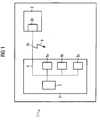
- HMI device 1 shows a schematic representation of a known data processing unit 1, for example, HMI device, in particular HMI display panel.
- HMI device 1 consists of a control unit 5, for example, printed circuit board, and a Display unit 2, for example a display, in particular an LCD display via a data transmission device 4, 4a, for example consisting of a CPU address and data bus and a connected ribbon cable, connected to each other.
- the display 2 points an integrated display controller 2a, the control signals or data transmitted by the printed circuit board 5, evaluates and implements.
- the display 2, in particular LCD display, of the HMI device 1 is thus over the ribbon cable 4a, or also called foil line, driven.
- the printed circuit board 5 has a command unit 3, for example CPU (Central Processing Unit), and other components 8a, 8b, 8c, for example, RAM memory, etc., on, on a data bus 4, such as a CPU address and data bus are connected. Via the data bus 4, the components 8a, 8b, 8c, the printed circuit board 5 is driven by the CPU 3 or exchanged data. Thus, there is constant traffic on the data bus 4 before.
- a command unit 3 for example CPU (Central Processing Unit)
- other components 8a, 8b, 8c for example, RAM memory, etc.
- FIG 1 is further shown that the data bus 4 directly with the ribbon cable 4a and this with the display Controller 2a is connected directly. It is thus no active components between the CPU 3 and the display 2.
- About the ribbon cable 4a are therefore all signals that are transmitted via the data bus 4 and then on the display 2 if the signals or data are not for the display controller 2a and the display 2, but for example the components 8a, 8b, 8c, are determined.
- This traffic is a constant change of signal edges connected to the lines, which has a corresponding noise emission 9 effect. Since it is in the ribbon cable 4a usually around a relatively long pipe that is several inches Depending on the design and cable routing, it can to u. strong, but at least permanent Noise emissions 9.
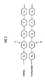
- FIG. 2 shows an exemplary comparison of the data traffic on the data bus 4 and the ribbon cable 4a of the known HMI device 1.
- the rhombuses of the respective data traffic 11, 12 symbolize the data, or signals, for example Control signals via the data bus 4 or the ribbon cable 4a are transmitted.
- the numbers in the diamonds of each Traffic 11, 12 symbolize the respective Receiver, according to the names of FIG 1. It shows that the data traffic 11 on the data bus 4 identical with the traffic being 12, which is via the ribbon cable 4a is applied to the display controller 2a of the display 2.
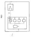
- this is a decoupling unit 6, for example, a driver module, between the data bus 4 and the ribbon cable 4a installed so that the direct connection between the display 2, in particular the display controller 2a, and the CPU 3 is interrupted. Data or signals which are transmitted via the data bus 4, are therefore not automatically on the display controller 2a at.
- the driver module 6 is both activated and deactivated. According to the invention, a data transmission to the Display controller 2a, for example, from the CPU 3, only in activated state of the driver module 6 possible. In deactivated State of the driver chip 6 are CPU 3 and display 2 physically decoupled. This requires the driver block 6 can be switched to a high-impedance state.
- the decoupling invention Due to the decoupling invention it comes on the Ribbon cable 4a to no signal edge change while For example, the CPU 3 to other components 8a, 8b, 8c, For example, the RAM memory, which also accesses the Noise radiation 9 on the ribbon cable 4 a in these cases is avoided because during CPU access to other components 8a, 8b, 8c, the connection of the CPU 3 to the display 2 quasi interrupted, i. the traffic on the data bus 4 in these cases for the display controller 2a and the Display 2 remains invisible. Signals or data are only then transferred to the display controller 2a when the driver chip 6 is activated, i. only if a transmission of data or signals to the display 2 are provided.
- the driver module 6 activates at a transmission of data necessary for the display controller 2a are determined, even. Is the data transmission terminated to the display controller 2a, the driver module moves automatically turn itself back to the deactivated Status. An external control is not necessary.
- the Control signals for activation or deactivation of the driver module 6 can of course also from the CPU 3 via the data bus 4 are transmitted to the driver module 6.
- the driver module 6 with a resistor 7, for example a pull-up or a Pull-down resistor, coupled.
- a resistor 7 for example a pull-up or a Pull-down resistor
- By combining with Such a pull-up resistor is activated during the transition from State in the deactivated state of the driver block 6 the edge steepness in the signal or data transmission lowered to the display controller. This creates a lower noise emission 9 on the ribbon cable 4a.
- Driver chips 6 are very inexpensive and can very easy with resistors 7, in particular pull-up or Pull-down resistors are combined so that conventional ones Data processing units 1, for example HMI devices, can be retrofitted very easily and inexpensively.
- Noise emissions or interference radiation via the ribbon cable 4a stand so only in the direct data or Signal transmission to the display controller 2a and the display 2, in which case the noise emissions through the Combination of driver chip 6 with pull-up or pull-down resistors 7 is minimized. This also happens to a smaller dispersion of the radiation values at the individual HMI devices of a production series. Furthermore the data bus 4 experiences a lower capacitive load through the display 2 and the ribbon cable 4a. On costly Shielding measures of the ribbon cable 4a, for example by ferrite, can in the inventive arrangement be completely dispensed with. By the invention lower noise emission 9 on the ribbon cable 4a between Display 2, in particular LCD display, and printed circuit board In addition, there are additional cost advantages shortened development times, otherwise in the reduction the disturbance radiation 9 incurred by constructive measures would.
- the inventive HMI device 1 can be particularly advantageous for operating and monitoring of or in industrial plants, In particular, automation systems are used.
- FIG. 4 shows an exemplary comparison of the data traffic on the data bus 4 and the ribbon cable 4a of the invention HMI device 1.
- the numbers in symbolize the diamonds of the respective data traffic 13, 14 again the respective recipients, according to the designations FIG. 1 shows that the data traffic 14, which via the ribbon cable 4a on the display controller 2a of the display 2 is present, compared to the traffic 13, the on the data bus 4 is applied, by the inventive arrangement on the transmission of data to the display controller 2a is limited. All other data transfers are only on Data bus 4 on.
- the present invention relates to a data processing unit 1, for example HMI device, with a Decoupling unit 6, for example a driver module.
- the HMI device 1 consists of a control unit 5, for example, printed circuit board, and a display unit 2, For example, display, via a ribbon cable 4a with each other are connected.
- the driver module according to the invention 6 ensures that noise emissions 9, during data transmission between printed circuit board 5 and display 2 on the Ribbon cables 4a arise to be minimized.
Landscapes
- Engineering & Computer Science (AREA)
- Physics & Mathematics (AREA)
- Computer Hardware Design (AREA)
- General Physics & Mathematics (AREA)
- Theoretical Computer Science (AREA)
- Control Of Indicators Other Than Cathode Ray Tubes (AREA)
Applications Claiming Priority (4)
| Application Number | Priority Date | Filing Date | Title |
|---|---|---|---|
| DE20314961U DE20314961U1 (de) | 2003-09-26 | 2003-09-26 | Datenverarbeitungseinheit mit Entkopplungseinheit |
| DE10344864 | 2003-09-26 | ||
| DE20314961U | 2003-09-26 | ||
| DE10344864A DE10344864A1 (de) | 2003-09-26 | 2003-09-26 | Datenverarbeitungseinheit mit Entkopplungseinheit |
Publications (3)
| Publication Number | Publication Date |
|---|---|
| EP1519257A2 true EP1519257A2 (fr) | 2005-03-30 |
| EP1519257A3 EP1519257A3 (fr) | 2009-03-04 |
| EP1519257B1 EP1519257B1 (fr) | 2013-04-24 |
Family
ID=34195774
Family Applications (1)
| Application Number | Title | Priority Date | Filing Date |
|---|---|---|---|
| EP04022728.2A Expired - Lifetime EP1519257B1 (fr) | 2003-09-26 | 2004-09-23 | Unité de traitement de données avec une unité de découplage |
Country Status (1)
| Country | Link |
|---|---|
| EP (1) | EP1519257B1 (fr) |
Cited By (1)
| Publication number | Priority date | Publication date | Assignee | Title |
|---|---|---|---|---|
| WO2013120443A1 (fr) * | 2012-02-13 | 2013-08-22 | 施耐德电器工业公司 | Appareil d'interface homme-machine et armoire de commande comprenant celui-ci |
Citations (4)
| Publication number | Priority date | Publication date | Assignee | Title |
|---|---|---|---|---|
| GB2152761A (en) | 1983-12-15 | 1985-08-07 | Citizen Watch Co Ltd | A liquid crystal display device |
| US6237056B1 (en) | 2000-07-14 | 2001-05-22 | Videon, Inc. | Apparatus and method for high speed board-to board ribbon cable data transfer |
| US20010050659A1 (en) | 2000-06-12 | 2001-12-13 | Yuji Sato | Image display system and display device |
| US6510525B1 (en) | 1999-04-26 | 2003-01-21 | Mediaq, Inc. | Method and apparatus to power up an integrated device from a low power state |
-
2004
- 2004-09-23 EP EP04022728.2A patent/EP1519257B1/fr not_active Expired - Lifetime
Patent Citations (4)
| Publication number | Priority date | Publication date | Assignee | Title |
|---|---|---|---|---|
| GB2152761A (en) | 1983-12-15 | 1985-08-07 | Citizen Watch Co Ltd | A liquid crystal display device |
| US6510525B1 (en) | 1999-04-26 | 2003-01-21 | Mediaq, Inc. | Method and apparatus to power up an integrated device from a low power state |
| US20010050659A1 (en) | 2000-06-12 | 2001-12-13 | Yuji Sato | Image display system and display device |
| US6237056B1 (en) | 2000-07-14 | 2001-05-22 | Videon, Inc. | Apparatus and method for high speed board-to board ribbon cable data transfer |
Cited By (3)
| Publication number | Priority date | Publication date | Assignee | Title |
|---|---|---|---|---|
| WO2013120443A1 (fr) * | 2012-02-13 | 2013-08-22 | 施耐德电器工业公司 | Appareil d'interface homme-machine et armoire de commande comprenant celui-ci |
| EP2804062A4 (fr) * | 2012-02-13 | 2015-08-19 | Schneider Electric Ind Sas | Appareil d'interface homme-machine et armoire de commande comprenant celui-ci |
| US20160018801A1 (en) * | 2012-02-13 | 2016-01-21 | Schneider Electric Industries Sas | Human-machine interface apparatus and control cabinet comprising same |
Also Published As
| Publication number | Publication date |
|---|---|
| EP1519257A3 (fr) | 2009-03-04 |
| EP1519257B1 (fr) | 2013-04-24 |
Similar Documents
| Publication | Publication Date | Title |
|---|---|---|
| EP1279076B1 (fr) | Procede de commande et installation de production industrielle equipee d'un systeme de commande par le web | |
| EP1415208B1 (fr) | Procede et systeme de conduite de processus pour exploiter une installation technique | |
| DE3004827C2 (de) | Datenverarbeitungsanlage | |
| DE10211939A1 (de) | Kopplungsvorrichtung zum Ankoppeln von Geräten an ein Bussystem | |
| DE10203370A1 (de) | Verfahren zur Steuerung einer fensterorientierten Bedienoberfläche und ein HMI Gerät zur Durchführung des Verfahrens | |
| DE102016000126B4 (de) | Serielles Bussystem mit Koppelmodulen | |
| EP2016470A1 (fr) | Terminal de commande pour l'echange d'informations avec un appareil sur site dans un systeme d'automatisation | |
| EP1431877A2 (fr) | Système de paramétrage-/diagnostic pour un appareil de terrain | |
| EP3637205A1 (fr) | Déclenchement de l'image sur une station client de l'opérateur | |
| EP0782722B1 (fr) | Procede et dispositif permettant de commander et d'activer des detecteurs et/ou des organes d'actionnement relies par un systeme de bus | |
| DE102011077318B4 (de) | Simulationssystem, Verfahren zur Durchführung einer Simulation, Leitsystem und Computerprogrammprodukt | |
| EP0862763B1 (fr) | Unite de simulation d'une unite peripherique d'une commande modulaire a memoire programmable | |
| EP2422248A1 (fr) | Système et procédé de répartition de données de projets d'une commande de sécurité d'une installation automatisée aux composants de commande | |
| DE102007063291A1 (de) | Sicherheitssteuerung | |
| EP2942686B1 (fr) | Système de commande et de transmission de données pour la transmission de données liées à la sécurité par l'intermédiaire d'un support de communication | |
| EP1519257B1 (fr) | Unité de traitement de données avec une unité de découplage | |
| EP2881812B1 (fr) | Procédé de fonctionnement d'un dispositif d'automatisation | |
| DE10119151A1 (de) | Diagnose-Einrichtung für einen Feldbus mit steuerungsunabhängiger Informationsübermittlung | |
| EP4123396B1 (fr) | Technique destinée à la réalisation d'une visualisation pour une installation technique d'automatisation dotée d'une commande à mémoire programmable | |
| EP1493067B1 (fr) | Procede de projection et/ou d'utilisation d'un systeme d'automatisation | |
| EP1779206B1 (fr) | Unite peripherique pour appareil d'automatisation | |
| DE69918829T2 (de) | Steuerungssystem zur steuerung von prozessgeräten | |
| DE20314961U1 (de) | Datenverarbeitungseinheit mit Entkopplungseinheit | |
| EP3141970B1 (fr) | Peripherie decentralisee | |
| DE102005007477B4 (de) | Programmierbare Steuerung zur Maschinen-und/oder Anlagenautomatisierung mit Standard-Steuerungs- und Sicherheitsfunktionen und Kommunikation mit einer Sicherheits-EA sowie Verfahren zum Betrieb der programmierbaren Steuerung |
Legal Events
| Date | Code | Title | Description |
|---|---|---|---|
| PUAI | Public reference made under article 153(3) epc to a published international application that has entered the european phase |
Free format text: ORIGINAL CODE: 0009012 |
|
| AK | Designated contracting states |
Kind code of ref document: A2 Designated state(s): AT BE BG CH CY CZ DE DK EE ES FI FR GB GR HU IE IT LI LU MC NL PL PT RO SE SI SK TR |
|
| AX | Request for extension of the european patent |
Extension state: AL HR LT LV MK |
|
| PUAL | Search report despatched |
Free format text: ORIGINAL CODE: 0009013 |
|
| AK | Designated contracting states |
Kind code of ref document: A3 Designated state(s): AT BE BG CH CY CZ DE DK EE ES FI FR GB GR HU IE IT LI LU MC NL PL PT RO SE SI SK TR |
|
| AX | Request for extension of the european patent |
Extension state: AL HR LT LV MK |
|
| 17P | Request for examination filed |
Effective date: 20090810 |
|
| 17Q | First examination report despatched |
Effective date: 20090902 |
|
| AKX | Designation fees paid |
Designated state(s): DE FR GB IT |
|
| GRAP | Despatch of communication of intention to grant a patent |
Free format text: ORIGINAL CODE: EPIDOSNIGR1 |
|
| GRAS | Grant fee paid |
Free format text: ORIGINAL CODE: EPIDOSNIGR3 |
|
| RAP1 | Party data changed (applicant data changed or rights of an application transferred) |
Owner name: SIEMENS AKTIENGESELLSCHAFT |
|
| GRAA | (expected) grant |
Free format text: ORIGINAL CODE: 0009210 |
|
| AK | Designated contracting states |
Kind code of ref document: B1 Designated state(s): DE FR GB IT |
|
| REG | Reference to a national code |
Ref country code: GB Ref legal event code: FG4D Free format text: NOT ENGLISH |
|
| REG | Reference to a national code |
Ref country code: DE Ref legal event code: R096 Ref document number: 502004014129 Country of ref document: DE Effective date: 20130620 |
|
| PGFP | Annual fee paid to national office [announced via postgrant information from national office to epo] |
Ref country code: FR Payment date: 20130924 Year of fee payment: 10 Ref country code: GB Payment date: 20130911 Year of fee payment: 10 |
|
| PGFP | Annual fee paid to national office [announced via postgrant information from national office to epo] |
Ref country code: IT Payment date: 20130921 Year of fee payment: 10 |
|
| PGFP | Annual fee paid to national office [announced via postgrant information from national office to epo] |
Ref country code: DE Payment date: 20131120 Year of fee payment: 10 |
|
| PLBE | No opposition filed within time limit |
Free format text: ORIGINAL CODE: 0009261 |
|
| STAA | Information on the status of an ep patent application or granted ep patent |
Free format text: STATUS: NO OPPOSITION FILED WITHIN TIME LIMIT |
|
| 26N | No opposition filed |
Effective date: 20140127 |
|
| REG | Reference to a national code |
Ref country code: DE Ref legal event code: R097 Ref document number: 502004014129 Country of ref document: DE Effective date: 20140127 |
|
| REG | Reference to a national code |
Ref country code: DE Ref legal event code: R119 Ref document number: 502004014129 Country of ref document: DE |
|
| GBPC | Gb: european patent ceased through non-payment of renewal fee |
Effective date: 20140923 |
|
| REG | Reference to a national code |
Ref country code: DE Ref legal event code: R119 Ref document number: 502004014129 Country of ref document: DE Effective date: 20150401 |
|
| REG | Reference to a national code |
Ref country code: FR Ref legal event code: ST Effective date: 20150529 |
|
| PG25 | Lapsed in a contracting state [announced via postgrant information from national office to epo] |
Ref country code: DE Free format text: LAPSE BECAUSE OF NON-PAYMENT OF DUE FEES Effective date: 20150401 Ref country code: GB Free format text: LAPSE BECAUSE OF NON-PAYMENT OF DUE FEES Effective date: 20140923 |
|
| PG25 | Lapsed in a contracting state [announced via postgrant information from national office to epo] |
Ref country code: FR Free format text: LAPSE BECAUSE OF NON-PAYMENT OF DUE FEES Effective date: 20140930 Ref country code: IT Free format text: LAPSE BECAUSE OF NON-PAYMENT OF DUE FEES Effective date: 20140923 |