EP1519300A2 - Formerkennung von handgezeichneten Objekten - Google Patents
Formerkennung von handgezeichneten Objekten Download PDFInfo
- Publication number
- EP1519300A2 EP1519300A2 EP04019840A EP04019840A EP1519300A2 EP 1519300 A2 EP1519300 A2 EP 1519300A2 EP 04019840 A EP04019840 A EP 04019840A EP 04019840 A EP04019840 A EP 04019840A EP 1519300 A2 EP1519300 A2 EP 1519300A2
- Authority
- EP
- European Patent Office
- Prior art keywords
- container
- strokes
- recognizer
- connector
- recognition
- Prior art date
- Legal status (The legal status is an assumption and is not a legal conclusion. Google has not performed a legal analysis and makes no representation as to the accuracy of the status listed.)
- Granted
Links
Images


Classifications
-
- G—PHYSICS
- G06—COMPUTING OR CALCULATING; COUNTING
- G06V—IMAGE OR VIDEO RECOGNITION OR UNDERSTANDING
- G06V30/00—Character recognition; Recognising digital ink; Document-oriented image-based pattern recognition
- G06V30/10—Character recognition
- G06V30/14—Image acquisition
- G06V30/142—Image acquisition using hand-held instruments; Constructional details of the instruments
- G06V30/1423—Image acquisition using hand-held instruments; Constructional details of the instruments the instrument generating sequences of position coordinates corresponding to handwriting
-
- G—PHYSICS
- G06—COMPUTING OR CALCULATING; COUNTING
- G06V—IMAGE OR VIDEO RECOGNITION OR UNDERSTANDING
- G06V30/00—Character recognition; Recognising digital ink; Document-oriented image-based pattern recognition
- G06V30/40—Document-oriented image-based pattern recognition
- G06V30/42—Document-oriented image-based pattern recognition based on the type of document
- G06V30/422—Technical drawings; Geographical maps
Definitions
- the invention relates generally to computer systems, and more particularly to an improved system and method for shape recognition of hand-drawn objects.
- the ability to recognize the shape of hand-drawn objects is important for users to be able to draw directly on their computers using ink input or ink notes.
- Current hardware and software may be able to capture ink representing handwriting reasonably well but is currently unable to similarly recognize and represent the meaning of hand-drawn objects.
- users instead use menu-based application programs to create drawings of objects.
- Various shapes may be presented by such application programs for a user to select and copy onto a drawing grid. The copied shape may then be resized to the desired scale and a user may continue to place and resize additional shapes onto the drawing grid until the drawing is complete.
- a shape recognizer may recognize a drawing such as a diagram or chart from ink input.
- the shape recognizer may include a container recognizer for recognizing closed containers and a connector recognizer for recognizing unclosed connectors in the drawing.
- the container recognizer may include any number of shape classifiers including an ellipse/circle classifier, a polygon classifier, a triangle classifier, a quadrilateral classifier, and so forth.
- the connector recognizer may include a skeleton recognizer, an arrowhead recognizer and various other recognizers to identify the type of connector between containers in a drawing.
- the present invention may recognize hand-drawn shapes by first performing container recognition for each container to identify the closed shapes, including circles, triangles, quadrilaterals, pentagons, hexagons, and so forth.
- One embodiment may employ a decision tree that may combine both global statistical features for identifying a shape, such as a triangle, and rule-based descriptions of specific types of that identified shape, such as distinguishing an isosceles triangle from an equilateral or right-angled triangle.
- the global statistical features may be robust to local variations such as over-tracing and overlapping of strokes, and rule-based descriptions may provide more detailed information of shapes including several types of quadrilaterals such as a trapezoid, a parallelogram, a diamond, a rectangle, and a square.
- Connector recognition may then be performed for each connector to identify the shape of the unclosed connectors, including skeletons, arrowheads and so forth.
- polylines may be used to approximate a skeleton.
- the present invention may handle continuation strokes of the skeleton, overlapping strokes of the skeleton and over-tracing strokes of the skeleton. After a skeleton of a connector may be recognized, an arrowhead at one or both ends of the skeleton may be recognized.
- the system and method are insensitive to stroke input order and the number of strokes that may form a hand-drawn shape. Furthermore, the system and method may be used to recognize any closed containers and unclosed connectors in a drawing. When recognized, the type, location, orientation and size of the shape can be provided.
- FIG. 1 illustrates an example of a suitable computing system environment 100 on which the invention may be implemented.
- the computing system environment 100 is only one example of a suitable computing environment and is not intended to suggest any limitation as to the scope of use or functionality of the invention. Neither should the computing environment 100 be interpreted as having any dependency or requirement relating to any one or combination of components illustrated in the exemplary operating environment 100.
- the invention is operational with numerous other general purpose or special purpose computing system environments or configurations.
- Examples of well known computing systems, environments, and/or configurations that may be suitable for use with the invention include, but are not limited to: personal computers, server computers, hand-held or laptop devices, tablet devices, headless servers, multiprocessor systems, microprocessor-based systems, set top boxes, programmable consumer electronics, network PCs, minicomputers, mainframe computers, distributed computing environments that include any of the above systems or devices, and the like.
- the invention may be described in the general context of computer-executable instructions, such as program modules, being executed by a computer.
- program modules include routines, programs, objects, components, data structures, and so forth, which perform particular tasks or implement particular abstract data types.
- the invention may also be practiced in distributed computing environments where tasks are performed by remote processing devices that are linked through a communications network.
- program modules may be located in local and/or remote computer storage media including memory storage devices.
- an exemplary system for implementing the invention includes a general purpose computing device in the form of a computer 110.
- Components of the computer 110 may include, but are not limited to, a processing unit 120, a system memory 130, and a system bus 121 that couples various system components including the system memory to the processing unit 120.
- the system bus 121 may be any of several types of bus structures including a memory bus or memory controller, a peripheral bus, and a local bus using any of a variety of bus architectures.
- such architectures include Industry Standard Architecture (ISA) bus, Micro Channel Architecture (MCA) bus, Enhanced ISA (EISA) bus, Video Electronics Standards Association (VESA) local bus, and Peripheral Component Interconnect (PCI) bus also known as Mezzanine bus.
- ISA Industry Standard Architecture
- MCA Micro Channel Architecture
- EISA Enhanced ISA
- VESA Video Electronics Standards Association
- PCI Peripheral Component Interconnect
- the computer 110 typically includes a variety of computer-readable media.
- Computer-readable media can be any available media that can be accessed by the computer 110 and includes both volatile and nonvolatile media, and removable and non-removable media.
- Computer-readable media may comprise computer storage media and communication media.
- Computer storage media includes volatile and nonvolatile, removable and non-removable media implemented in any method or technology for storage of information such as computer-readable instructions, data structures, program modules or other data.
- Computer storage media includes, but is not limited to, RAM, ROM, EEPROM, flash memory or other memory technology, CD-ROM, digital versatile disks (DVD) or other optical disk storage, magnetic cassettes, magnetic tape, magnetic disk storage or other magnetic storage devices, or any other medium which can be used to store the desired information and which can accessed by the computer 110.
- Communication media typically embodies computer-readable instructions, data structures, program modules or other data in a modulated data signal such as a carrier wave or other transport mechanism and includes any information delivery media.
- modulated data signal means a signal that has one or more of its characteristics set or changed in such a manner as to encode information in the signal.
- communication media includes wired media such as a wired network or direct-wired connection, and wireless media such as acoustic, RF, infrared and other wireless media. Combinations of the any of the above should also be included within the scope of computer-readable media.
- the system memory 130 includes computer storage media in the form of volatile and/or nonvolatile memory such as read only memory (ROM) 131 and random access memory (RAM) 132.
- ROM read only memory
- RAM random access memory
- BIOS basic input/output system
- RAM 132 typically contains data and/or program modules that are immediately accessible to and/or presently being operated on by processing unit 120.
- FIG. 1 illustrates operating system 134, application programs 135, other program modules 136 and program data 137.
- the computer 110 may also include other removable/non-removable, volatile/nonvolatile computer storage media.
- FIG. 1 illustrates a hard disk drive 141 that reads from or writes to non-removable, nonvolatile magnetic media, a magnetic disk drive 151 that reads from or writes to a removable, nonvolatile magnetic disk 152, and an optical disk drive 155 that reads from or writes to a removable, nonvolatile optical disk 156 such as a CD ROM or other optical media.
- removable/non-removable, volatile/nonvolatile computer storage media that can be used in the exemplary operating environment include, but are not limited to, magnetic tape cassettes, flash memory cards, digital versatile disks, digital video tape, solid state RAM, solid state ROM, and the like.
- the hard disk drive 141 is typically connected to the system bus 121 through a non-removable memory interface such as interface 140, and magnetic disk drive 151 and optical disk drive 155 are typically connected to the system bus 121 by a removable memory interface, such as interface 150.
- hard disk drive 141 is illustrated as storing operating system 144, application programs 145, other program modules 146 and program data 147. Note that these components can either be the same as or different from operating system 134, application programs 135, other program modules 136, and program data 137. Operating system 144, application programs 145, other program modules 146, and program data 147 are given different numbers herein to illustrate that, at a minimum, they are different copies.
- a user may enter commands and information into the computer 110 through input devices such as a tablet, or electronic digitizer, 164, a microphone 163, a keyboard 162 and pointing device 161, commonly referred to as mouse, trackball or touch pad.
- Other input devices not shown in FIG. 1 may include a joystick, game pad, satellite dish, scanner, or other devices including a device that contains a biometric sensor, environmental sensor, position sensor, or other type of sensor.
- a user input interface 160 that is coupled to the system bus, but may be connected by other interface and bus structures, such as a parallel port, game port or a universal serial bus (USB).
- USB universal serial bus
- a monitor 191 or other type of display device is also connected to the system bus 121 via an interface, such as a video interface 190.
- the monitor 191 may also be integrated with a touch-screen panel or the like.
- the monitor and/or touch screen panel can be physically coupled to a housing in which the computing device 110 is incorporated, such as in a tablet-type personal computer.
- computers such as the computing device 110 may also include other peripheral output devices such as speakers 195 and printer 196, which may be connected through an output peripheral interface 194 or the like.
- the computer 110 may operate in a networked environment using logical connections to one or more remote computers, such as a remote computer 180.
- the remote computer 180 may be a personal computer, a server, a router, a network PC, a peer device or other common network node, and typically includes many or all of the elements described above relative to the computer 110, although only a memory storage device 181 has been illustrated in FIG. 1.
- the logical connections depicted in FIG. 1 include a local area network (LAN) 171 and a wide area network (WAN) 173, but may also include other networks.
- LAN local area network
- WAN wide area network
- Such networking environments are commonplace in offices, enterprise-wide computer networks, intranets and the Internet.
- the computer 110 When used in a LAN networking environment, the computer 110 is connected to the LAN 171 through a network interface or adapter 170. When used in a WAN networking environment, the computer 110 typically includes a modem 172 or other means for establishing communications over the WAN 173, such as the Internet.
- the modem 172 which may be internal or external, may be connected to the system bus 121 via the user input interface 160 or other appropriate mechanism.
- program modules depicted relative to the computer 110, or portions thereof may be stored in the remote memory storage device.
- FIG. 1 illustrates remote application programs 185 as residing on memory device 181. It will be appreciated that the network connections shown are exemplary and other means of establishing a communications link between the computers may be used.
- the present invention is generally directed towards a system and method for providing shape recognition of hand-drawn objects.
- hand-drawn object means any handwritten non-character shape or drawing.
- a user may draw diagrams and flow charts freely without restrictions on the hand-drawn input.
- One shape may have many strokes and the input order of strokes may be arbitrary so that the system and method may accept any ink as input.
- ink generally means a handwritten stroke or strokes.
- the strokes could be over-traced or overlapped. For either case, the system and method may automatically detect the correct shapes.
- the system and method may recognize the hand-drawn shape of containers and connectors drawn between containers.
- a container means any closed drawing object.
- a connector means any drawing object joining containers.
- FIG. 2 of the drawings there is shown a block diagram generally representing an exemplary architecture of system components for shape recognition of hand-drawn objects.
- Those skilled in the art will appreciate that the functionality implemented within the blocks illustrated in the diagram may be implemented as separate components or the functionality of several or all of the blocks may be implemented within a single component.
- the functionality for the chart detector 204 may be included in the shape recognizer 206.
- the functionality of the container recognizer 208 may be implemented as a separate component.
- the ink parser 202 may accept any ink, including ink of a drawing object.
- the ink parser 202 may include an operably coupled chart detector 204 and an operably coupled shape recognizer 206.
- the chart detector 204 and the shape recognizer 206 may be any type of executable software code such as a kernel component, an application program, a linked library, an object, and so forth.
- the chart detector 204 may include an operably coupled container detector 212 and an operably coupled connector detector 214, and the shape recognizer 206 may include an operably coupled container recognizer 208 and an operably coupled connector recognizer 210.
- the container recognizer 208 may include any number of operably coupled classifiers such as an ellipse/circle classifier 216, a polygon classifier 218, a triangle classifier 220, a quadrilateral classifier 222, and so forth.
- the connector recognizer 210 may include any number of operably coupled recognizers such as a skeleton recognizer 224, an arrowhead recognizer 226, and so forth. Each of these components may also be any type of executable software code such as a kernel component, an application program, a linked library, an object, or other type of executable software code.
- FIG. 3 presents a flowchart generally representing the steps undertaken for shape recognition of hand-drawn objects.
- any ink may be parsed, including ink of a drawing object.
- a page of ink may be accepted as input and parsed.
- the ink parser for example, may have no a priori knowledge of the ink on the page. Therefore, fundamental algorithms such as word grouping, writing/drawing classification and drawing grouping may be executed.
- word grouping strokes may be grouped into hierarchies of words, lines, and blocks. To do so, the word grouping process may include feature extraction of strokes to capture distance, geometric dissimilarity and linearity, and other stroke features.
- the word grouping process may also include dynamic programming to group the strokes according to temporal information.
- the word grouping process may also include clustering to group the strokes according to spatial information.
- the words, lines and blocks identified in the groups may not necessarily correspond to real semantic words, lines and blocks. In fact, these groups may include strokes of hand-drawn objects.
- various features may be identified that may differentiate writing from drawing. For instance, single word features such as curvature, density, and other handwriting model features, may be used to differentiate writing from drawing.
- context features such as temporal and spatial context features, may be used to differentiate writing from drawing.
- Each of the various features may be mapped to a fuzzy function, and classification between writing and drawing may be determined according to a combination of the fuzzy functions.
- the drawing strokes may be well organized by performing drawing grouping.
- the drawing strokes may be grouped into independent objects according to the spatial relationship among them.
- An efficient grid-based approach may be used for fitting the ink strokes into an image grid with an appropriate size.
- the image grid may be labeled to find connected components. Each connected component may correspond to a drawing object. Heuristic rules may then be applied to adjust the drawing objects.
- chart detection may be performed to group drawing strokes by finding all the strokes that may belong to a drawing object.
- a user can draw diagrams and flow charts freely without any restriction on the input.
- one shape may have many strokes and the input order may be arbitrary.
- the strokes could be over-traced or overlapped.
- the system may automatically detect the correct shapes.
- a hypergraph may be used to represent the diagrams and flow chart so that the relationship between containers and connectors may be fully represented.
- connectors that may join more than two containers may be supported in this embodiment.
- the container detector 212 may find all the strokes that belong to a container and the connector detector 214 may find all the strokes that belong to a connector. To do so, an optimal search may be performed in time order to detect any containers. Then an efficient search may be performed to detect containers and connectors. Finally, content detection may be performed for each detected container.
- shape recognition may be performed to recognize containers and connectors.
- the shape recognition engine 206 may be used to recognize closed containers and unclosed connectors in a drawing such as diagram or chart.
- the type, location, orientation and size of the shape can be provided.
- the order of stroke input and the number of strokes do not affect the recognition.
- the drawing may be generated at step 308.
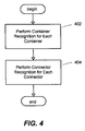
- FIG. 4 presents a flowchart generally representing one embodiment of the steps undertaken for shape recognition of containers and connectors indicated at step 306.
- Container recognition may be performed at step 402 for each container to identify the closed shapes, including circles, triangles, quadrilaterals, pentagons, hexagons, and so forth.
- specific types of shapes may be recognized such as distinguishing a circle from an ellipse, or distinguishing an isosceles triangle from an equilateral or right-angled triangle.
- quadrilaterals may be recognized, including a trapezoid, a parallelogram, a diamond, a rectangle, and a square.
- the container recognizer 208 may employ a decision tree that may combine both global statistical features and rule-based descriptions of specific shapes.
- the global statistical features may be robust to local variations such as over-tracing, and rule-based descriptions may provide more detailed information of shapes. For instance, there may be a rule-based description for an isosceles triangle that may include a description of a triangle with two equal-length edges.
- connector recognition may be performed for each connector to identify the shape of the unclosed connectors, including skeletons, arrowheads and so forth.
- polylines may be used to approximate a skeleton.
- the connector recognizer 210 may handle continuation strokes of the skeleton, overlapping strokes of the skeleton and over-tracing strokes of the skeleton. After a skeleton of a connector may be recognized, an arrowhead at one or both ends of the skeleton may be recognized.
- the connector recognizer 210 may invoke the skeleton recognizer 224 and/or the arrowhead recognizer 226 for identifying a skeleton and an arrowhead of a connector, respectively.
- FIG. 5 presents an illustration generally representing a decision tree that may combine both global statistical features and rule-based descriptions of specific shapes for use in performing shape recognition.
- the strokes 502 grouped together that belong to a container may be input to a roundness test 504 to determine how likely the shape of the strokes may represent a circle or an ellipse.
- the roundness test 504 may then determine whether to apply the ellipse/circle classifier 506 or the polygon classifier 508 to identify the shape of the strokes 502.
- the ellipse/circle classifier 506 may determine whether the shape of the strokes may be an ellipse 510 or a circle 512.
- the polygon classifier 508 may determine whether the shape of the strokes may be a pentagon 518 or a hexagon 520, or whether to apply the triangle classifier 514 or the quadrilateral classifier 516 to identify the shape of the strokes 502.
- the triangle classifier 514 may determine whether the shape of the strokes may be a triangle and may also employ rule-based descriptions that may provide more detailed information for distinguishing whether the triangle may be an isosceles triangle 522, an equilateral triangle 524, or right-angled triangle 526.
- the quadrilateral classifier may determine whether the shape of the strokes may be a quadrilateral and may also employ rule-based descriptions that may provide more detailed information for distinguishing whether the quadrilateral may be a square 528, a rectangle 530, a diamond 532, trapezoid 534, or a parallelogram 536.
- FIG. 6 presents a flowchart generally representing an embodiment of the steps undertaken for recognizing the shape of a closed container identified within ink input.
- a roundness test may be performed to test how likely the shape is a circle or an ellipse. If the result of the roundness test indicates that the shape is likely to be a circle or an ellipse at step 604, then a process may be performed for recognition of a circle or an ellipse at step 606. If the result of the roundness test indicates that the shape is not likely to be a circle or an ellipse at step 604, then a process may be performed for recognition of a polygon at step 608.
- the process performed for recognition of a polygon at step 608 may indicate that the polygon may be a triangle or a quadrilateral. If the result of the process performed for recognition of a polygon indicates that the polygon may be a triangle at step 610, then a process may be performed for recognition of the specific type or subclass of triangle at step 612. For example, the specific type of triangle may be an isosceles triangle 522, an equilateral triangle 524, or right-angled triangle 526. However, if the result of the process performed for recognition of a polygon indicates that the polygon may be a quadrilateral at step 614, then a process may be performed for recognition of the specific type or subclass of quadrilateral at step 616.
- the specific type of quadrilateral may be a square 528, a rectangle 530, a diamond 532, trapezoid 534, or a parallelogram 536.
- the process performed for recognition of a polygon at step 608 may indicate that the polygon may be a pentagon 518 or a hexagon 520. If the result of the process performed for recognition of a polygon indicates that the polygon may be a pentagon at step 618, then a process may be performed for recognition of the pentagon at step 620. If the result of the process performed for recognition of a polygon indicates that the polygon may be a hexagon at step 622, then a process may be performed for recognition of the hexagon at step 624.
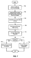
- FIG. 7 presents a flowchart generally representing an embodiment of the steps undertaken for performing a roundness test indicated at step 602.
- a threshold may be assigned for comparing the result of the roundness test to distinguish whether the shape of a closed container may be a circle/ellipse or a polygon.
- a feature such as the thinness ratio P ch 2 /A ch , where P ch and A ch represent the perimeter and the area of the shape's convex hull, respectively, may be used to test roundness.
- the strokes of the shape may be scaled to make the minimal bounding rectangle become a square.
- both circles and ellipses may have a minimal thinness ratio of 4* ⁇ , where ⁇ (pi) is defined as the ratio of the circumference of a circle to its diameter.
- ⁇ (pi) is defined as the ratio of the circumference of a circle to its diameter.
- the minimal bounding rectangle of the strokes may be determined and then the strokes of the shape may be scaled to make the minimal bounding rectangle become a square at step 704.
- the convex hull of the strokes of the shape may be calculated at step 706 using Graham's Algorithm (which may be found in Computational Geometry in C (2nd Ed.) by Joseph O'Rourke, Cambridge University Press, 1998, ISBN:0-521-64976-5).
- the thinness ratio P ch 2 /A ch may be calculated at step 708.
- the result of calculating the thinness ratio P ch 2 /A ch may be compared with a threshold at step 710.
- the threshold of 4* ⁇ *1.05 may be assigned. If the thinness ratio P ch 2 /A ch is less than or equal to the threshold of 4* ⁇ *1.05 at step 712, then the shape may be a circle or an ellipse, and a classifier may be used to further distinguish whether the shape of the closed container is either a circle or an ellipse at step 714.
- the shape may be a polygon and a polygon classifier may be used at step 716 to further distinguish the type of polygon that the shape of the closed container may be.
- a polygon classifier may be used at step 716 to further distinguish the type of polygon that the shape of the closed container may be.
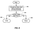
- FIG. 8 presents a flowchart generally representing the steps undertaken by a classifier to distinguish whether the shape of a closed container may be either a circle or an ellipse as indicated at step 714.
- a feature such as the width-height ratio of the minimal bounding rectangle may be used in one embodiment to classify circles from ellipses.
- the width-height ratio of the minimal bounding rectangle of the shape may be determined and then a determination may be made at step 804 whether the shape is either a circle 806 or an ellipse 808 according to a given threshold. In one embodiment, if the width-height ratio is near 1, such as within a range between 0.83 and 1.20, the shape may be classified as a circle; and an ellipse otherwise.
- thresholds and other features may be used to classify circles from ellipses.
- FIG. 9 presents a flowchart generally representing the steps undertaken by a classifier to distinguish the type of polygon that a shape of a closed container may be.
- a polygon shape test may be performed for each desired type of n-sided polygon to determine the shape of the polygon.
- the polygon shape test may be performed for a triangle, a quadrilateral, a pentagon, and a hexagon.
- One or more thresholds may be assigned for the polygon shape test for comparing the result of the polygon shape test performed for each desired type of n-sided polygon in order to distinguish which n-sided polygon the shape may be.
- a feature such as the area ratio A n /A ch , where A n represents the area of a maximal inscribed n-sided polygon within the convex hull and A ch represents the area of a convex hull of the strokes, may be used to determine the shape of the polygon.
- the convex hull of strokes may be calculated using Graham's Algorithm (which may be found in Computational Geometry in C (2nd Ed.) by Joseph O'Rourke, Cambridge University Press, 1998, ISBN:0-521-64976-5) and the area of the convex hull of strokes may be calculated at step 902.
- the largest inscribed n-sided polygon and its area A n may be calculated for each desired type of n-sided polygon at step 904.
- the largest inscribed n-sided polygon may be calculated using the algorithm proposed by Boyce found at: J.E. Boyce and D. P. Dobkin, Finding Extremal Polygons, SIAM Journal on Computing, 14(1):134-147, 1985.
- the largest inscribed triangle, quadrilateral, pentagon, hexagon and their respective areas A 3 , A 4 , A 5 and A 6 may be calculated.
- the area ratio A n /A ch may be calculated for each desired type of n-sided polygon.
- the area ratio A n /A ch for each desired type of n-sided polygon may be compared with the corresponding threshold at step 908. And finally, the n-sided polygon with the least edge count whose area ratio A n / A ch is greater than its corresponding threshold may be chosen at step 910 as the type of polygon that represents the shape of the closed container.
- the threshold for A 3 , A 4 , A 5 and A 6 may be 0.73, 0.84, 0.93 and 0.94, respectively.
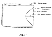
- FIG. 10 illustrates an example of the strokes of a shape 1002 with a maximal inscribed quadrilateral 1004 within a convex hull 1006 around the shape 1002.
- the area ratio of the inscribed quadrilateral and the convex hull may be greater than the corresponding threshold and have the least edge count when compared with the area ratio of other n-sided polygons such as a pentagon or hexagon. Consequently, the shape may be classified as a quadrilateral.
- the concave case may be tested to avoid false classification.
- the concave case may be tested by checking the maximal distance of points in the strokes and the edge of the recognized shape. For example, FIG. 11 illustrates a maximal distance 1102 between the points of the strokes of the hand-drawn shape 1002 and the edge of the recognized shape, the maximal inscribed quadrilateral 1004. The shape may not be classified as a quadrilateral if the maximal distance 1102 is larger than an empirical threshold.
- the sub-classes can be further classified as isosceles triangle. As an example, if all three sides of a triangle are almost equal, then the triangle may be further classified as an equilateral triangle. As yet another example, if the sum of the squares of any two sides approximately equals the square of the third side, then the triangle may be further classified as a right-angled triangle.
- the shape may be further classified as a square. If the lengths of all four sides are not almost equal and each pair of adjacent sides is almost perpendicular, the shape may be further classified as a rectangle. If each pair of opposite sides is almost parallel and any two adjacent sides are not almost perpendicular and the lengths of all four sides are almost equal, then the shape may be further classified as a diamond. If each pair of opposite sides is almost parallel and any two adjacent sides are not almost perpendicular and the lengths of all four sides are not almost equal, then the shape may be further classified as a parallelogram. If only one pair of opposite sides is almost parallel and any two adjacent sides are not almost perpendicular, then the shape may be further classified as a trapezoid.
- the edges of the polygon shapes may be refined for better representation at step 912.
- the distance between each point of the input strokes and the edges of the recognized polygon may be computed to determine to which edge of the recognized polygon that each point of the input strokes belongs.
- the position and orientation of each edge of the recognized polygon may be recomputed according to the robust regression results of the corresponding points of the input strokes.
- the edges of the shape 1204 recognized from the strokes of the hand-drawn shape 1202 may be better represented as illustrated in FIG. 12 by the shape with refinement 1206.
- FIG. 13 presents a flowchart generally representing the steps undertaken for recognizing the shape of a connector identified within ink input.
- the input for recognizing the shape of a connector may include the strokes and joint points with containers, as illustrated in FIG. 14, that may have been previously identified by the chart detector.
- a joint point as defined herein means a point of the connector's strokes that has the minimal distance to a container. For instance as illustrated in FIG. 14, there may be a joint point 1404 at each end of a connector 1406 where the joint point may attach to one of the containers 1402 and 1412.
- each connector may include a line or curve between either a joint point or arrowhead and another joint point or arrowhead, defined herein as a skeleton 1408, and each connector may include an arrowhead 1410 at either or both ends of the skeleton.
- some users may draw the skeleton of a connector using a back and forth motion with overlapping strokes.
- Other users may similarly draw an arrowhead of a connector using a back and forth motion.
- other users may draw the skeleton and the arrowhead of a connector in one single stroke.
- the strokes may be broken into pieces at points of the high curvature, herein defined as cusps. By parsing one stroke as a polyline, each non-ending point of the stroke may form an intersection of two line segments.
- the angle of two line segments at each non-ending point of the stroke may be computed and the strokes may be broken at points where the corresponding angle is less than a threshold such as 80 degrees.
- the strokes may first be smoothed in one embodiment by applying Sklansky's polyline approximation (which may be found in Sklansky J. and Gonzalez V., Fast Polygonal Approximation of Digitized Curves, Pattern Recognition, Vol.12, pp.327-331, 1980) to simplify and smooth the strokes.
- Sklansky's polyline approximation which may be found in Sklansky J. and Gonzalez V., Fast Polygonal Approximation of Digitized Curves, Pattern Recognition, Vol.12, pp.327-331, 1980
- the strokes or stroke pieces may be classified as either skeleton strokes or arrowhead strokes so that the skeleton strokes of the connector and the arrowhead strokes of the connector may be separately recognized.
- a stroke or stroke piece may be considered to be an arrowhead stroke if its size is less than an empirical threshold and its distance to the joint point is small.
- an empirical threshold may be 12.8 millimeters and the distance to the joint point may be less than 8.5 millimeters.
- Any strokes not considered arrowhead strokes may be classified as a skeleton stroke.
- the stroke or stroke pieces that have minimal distances to the center of the convex hull of the connector may be identified as a skeleton stroke or stroke pieces.
- the skeleton strokes or stroke pieces may be merged.
- the skeleton strokes or pieces to be merged may occur with one stroke or piece as separated from another stroke or piece, with one stroke or piece as overlapping another stroke or piece, or with one stroke or piece as overtracing another stroke or piece.
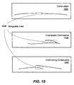
- a mergable area 1508 may be defined by constructing a quadrilateral that may contain the ends of the separated strokes or pieces of strokes that may form a continuation 1502 when merged, or may contain the overlapping area of the overlapping strokes or pieces of strokes that may form an overlapped continuation 1504 when merged, or may contain the overtracing area of the overtraced strokes or pieces of strokes that may form an overtraced continuation 1506 when merged.
- a connection score may be defined for each pair of strokes or pieces of strokes.
- this connection score may be larger when two strokes or pieces of strokes lie near and smaller when the strokes or pieces of strokes lie farther apart.
- a recursive merging process is performed by merging the two skeleton strokes or pieces of skeleton strokes with the highest connection score until there is no mergable stroke pair remaining.
- each merged skeleton stroke or stroke piece may be normalized to eliminate local fluctuations.
- Sklansky's polyline approximation (which may be found in Sklansky J. and Gonzalez V., Fast Polygonal Approximation of Digitized Curves, Pattern Recognition, Vol.12, pp.327-331, 1980) may be applied for each merged skeleton stroke or stroke piece for normalization.
- the final skeleton of the connector may be completely generated.
- the arrowhead strokes or pieces of strokes may be recognized.
- the convex hull of the arrowhead strokes or pieces of strokes may be tested to see if the shape is likely to be a triangle.
- a feature such as the area ratio A n /A ch , where A n represents the area of a maximal inscribed triangle and A ch represents the area of a convex hull of the strokes, may be used to determine the shape of the triangle.
- the convex hull of strokes may be calculated using Graham's Algorithm (which may be found in Computational Geometry in C (2nd Ed.) by Joseph O'Rourke, Cambridge University Press, 1998, ISBN:0-521-64976-5) and then the area of the convex hull of strokes A ch may be calculated.
- the largest inscribed triangle may be calculated using the algorithm proposed by Boyce (which may be found in J.E. Boyce and D. P. Dobkin, Finding Extremal Polygons, SIAM Journal on Computing, 14(1):134-147, 1985) and then its area A n may be calculated.
- the area ratio A n /A ch may be calculated and may be compared with a threshold, such as within a range close to 1, to determine that the shape of the arrowhead strokes or pieces of strokes may be a triangle.
- the concave case may be tested by checking the maximal distance of points in the strokes and the edge of the recognized triangle to avoid false classification. Then, the edges of the triangle may be refined for better representation. First, the distance between each point of the arrowhead strokes or stroke pieces and the edges of the triangle may be computed to determine to which edge of the recognized triangle that each point of the strokes or stroke pieces belongs. Then, the position and orientation of each edge of the recognized triangle may be recomputed according to the robust regression results of the corresponding points of the arrowhead strokes or stroke pieces. The complete connector may thus be generated by combining the final skeleton and any arrowheads recognized.
- the hand-drawn objects within the ink input may be completely recognized and generated.
- a user may draw diagrams and flow charts freely and without restrictions on the hand-drawn input.
- One shape may have many strokes and the input order of strokes may be arbitrary so that the system and method may accept any ink as input. Moreover, the strokes could be over-traced or overlapped. For either case, the system and method may automatically detect the correct shapes.
- the present invention provides a system and method for shape recognition of hand-drawn objects.
- the system and method are insensitive to stroke input order and the number of strokes that may form a hand-drawn shape.
- the system and method provided are flexible and extensible.
- the present invention may be used to recognize any closed containers and unclosed connectors in a drawing including a diagram and chart. When recognized, the type, location, orientation and size of the shape can be provided. The method and system thus provide significant advantages and benefits needed in contemporary computing.
Landscapes
- Engineering & Computer Science (AREA)
- Computer Vision & Pattern Recognition (AREA)
- Physics & Mathematics (AREA)
- General Physics & Mathematics (AREA)
- Multimedia (AREA)
- Theoretical Computer Science (AREA)
- Artificial Intelligence (AREA)
- Character Discrimination (AREA)
- Image Analysis (AREA)
Applications Claiming Priority (4)
| Application Number | Priority Date | Filing Date | Title |
|---|---|---|---|
| US50586703P | 2003-09-24 | 2003-09-24 | |
| US505867P | 2003-09-24 | ||
| US850718 | 2004-05-20 | ||
| US10/850,718 US7324691B2 (en) | 2003-09-24 | 2004-05-20 | System and method for shape recognition of hand-drawn objects |
Publications (3)
| Publication Number | Publication Date |
|---|---|
| EP1519300A2 true EP1519300A2 (de) | 2005-03-30 |
| EP1519300A3 EP1519300A3 (de) | 2006-02-15 |
| EP1519300B1 EP1519300B1 (de) | 2009-07-15 |
Family
ID=34198320
Family Applications (1)
| Application Number | Title | Priority Date | Filing Date |
|---|---|---|---|
| EP04019840A Expired - Lifetime EP1519300B1 (de) | 2003-09-24 | 2004-08-20 | Formerkennung von handgezeichneten Objekten |
Country Status (11)
| Country | Link |
|---|---|
| US (1) | US7324691B2 (de) |
| EP (1) | EP1519300B1 (de) |
| JP (1) | JP4536471B2 (de) |
| KR (1) | KR101099149B1 (de) |
| CN (1) | CN1607540B (de) |
| AU (1) | AU2004210502B2 (de) |
| BR (1) | BRPI0403894A (de) |
| CA (1) | CA2481826C (de) |
| DE (1) | DE602004021999D1 (de) |
| MX (1) | MXPA04008853A (de) |
| RU (1) | RU2372654C2 (de) |
Cited By (8)
| Publication number | Priority date | Publication date | Assignee | Title |
|---|---|---|---|---|
| EP1969489A4 (de) * | 2005-12-21 | 2009-04-01 | Microsoft Corp | Tabellendetektion in tintennotizen |
| US7664325B2 (en) | 2005-12-21 | 2010-02-16 | Microsoft Corporation | Framework for detecting a structured handwritten object |
| US7991233B2 (en) | 2006-12-13 | 2011-08-02 | Canon Kabushiki Kaisha | Method and apparatus for dynamic connector analysis |
| US8238666B2 (en) | 2006-12-13 | 2012-08-07 | Canon Kabushiki Kaisha | Recognition of parameterised shapes from document images |
| US9384403B2 (en) | 2014-04-04 | 2016-07-05 | Myscript | System and method for superimposed handwriting recognition technology |
| US20160247040A1 (en) * | 2014-12-02 | 2016-08-25 | Myscript | System and method for recognizing geometric shapes |
| US9524440B2 (en) | 2014-04-04 | 2016-12-20 | Myscript | System and method for superimposed handwriting recognition technology |
| WO2017137747A1 (en) * | 2016-02-08 | 2017-08-17 | Tommytrinder.Com Limited | Door and window frame designing by recognising and beautifying hand drawn strokes on a touchscreen |
Families Citing this family (66)
| Publication number | Priority date | Publication date | Assignee | Title |
|---|---|---|---|---|
| KR20040083788A (ko) * | 2003-03-25 | 2004-10-06 | 삼성전자주식회사 | 제스쳐 커맨드를 이용하여 프로그램을 구동시킬 수 있는휴대용 단말기 및 이를 이용한 프로그램 구동 방법 |
| US7295708B2 (en) * | 2003-09-24 | 2007-11-13 | Microsoft Corporation | System and method for detecting a list in ink input |
| US7352902B2 (en) * | 2003-09-24 | 2008-04-01 | Microsoft Corporation | System and method for detecting a hand-drawn object in ink input |
| US7623734B2 (en) * | 2004-09-30 | 2009-11-24 | Microsoft Corporation | Method and system for automatically inscribing noisy objects in scanned image data within a minimum area rectangle |
| US7680332B2 (en) * | 2005-05-30 | 2010-03-16 | Microsoft Corporation | Grouping lines in freeform handwritten text |
| JP2007072528A (ja) * | 2005-09-02 | 2007-03-22 | Internatl Business Mach Corp <Ibm> | 文書構造解析方法、プログラム、装置 |
| US8315482B2 (en) * | 2007-06-26 | 2012-11-20 | Microsoft Corporation | Integrated platform for user input of digital ink |
| US8600164B2 (en) * | 2008-03-28 | 2013-12-03 | Smart Technologies Ulc | Method and tool for recognizing a hand-drawn table |
| US8773432B2 (en) * | 2008-04-18 | 2014-07-08 | Adobe Systems Incorporated | Triangulation for accelerated multi-resolution rendering of stroked paths |
| CN101593270B (zh) * | 2008-05-29 | 2012-01-25 | 汉王科技股份有限公司 | 一种手绘形状识别的方法及装置 |
| US8620084B2 (en) | 2008-06-26 | 2013-12-31 | Microsoft Corporation | Shape recognition using partial shapes |
| CN101393648B (zh) * | 2008-10-07 | 2011-06-29 | 广东威创视讯科技股份有限公司 | 手绘几何图形的识别方法 |
| US8749497B2 (en) * | 2008-12-12 | 2014-06-10 | Apple Inc. | Multi-touch shape drawing |
| US8806354B1 (en) * | 2008-12-26 | 2014-08-12 | Avaya Inc. | Method and apparatus for implementing an electronic white board |
| US20100171754A1 (en) * | 2009-01-07 | 2010-07-08 | Microsoft Corporation | Converting digital ink to shapes and text |
| AU2009217445A1 (en) * | 2009-09-22 | 2011-04-07 | Canon Kabushiki Kaisha | Fast line linking |
| WO2012024829A1 (en) * | 2010-08-24 | 2012-03-01 | Nokia Corporation | Method and apparatus for segmenting strokes of overlapped handwriting into one or more groups |
| JP5741079B2 (ja) * | 2011-03-09 | 2015-07-01 | セイコーエプソン株式会社 | 画像生成装置およびプロジェクター |
| EP2521058A1 (de) | 2011-05-06 | 2012-11-07 | Dassault Systèmes | Bestimmung einer geometrischen CAD-Operation |
| EP2521059B1 (de) | 2011-05-06 | 2019-10-16 | Dassault Systèmes | Design-Operationen an in Abschnitten unterteilten Formen |
| EP2521057A1 (de) | 2011-05-06 | 2012-11-07 | Dassault Systèmes | Bestimmung eines Parameters einer geometrischen CAD-Operation |
| EP2521055B1 (de) | 2011-05-06 | 2019-07-10 | Dassault Systèmes | Auswahl von dreidimensionalen parametrischen Formen |
| EP2521056A1 (de) * | 2011-05-06 | 2012-11-07 | Dassault Systèmes | CAD-Design mit primitiven geschlossenen Formen |
| EP2523130B1 (de) | 2011-05-11 | 2024-12-25 | Dassault Systèmes | Verfahren zum Entwerfen eines geometrischen, dreidimensionalen, modellierten Objekts |
| US9117302B2 (en) * | 2011-11-30 | 2015-08-25 | Qualcomm Incorporated | Switching between direct rendering and binning in graphics processing using an overdraw tracker |
| US10368836B2 (en) * | 2012-12-26 | 2019-08-06 | Volcano Corporation | Gesture-based interface for a multi-modality medical imaging system |
| JP6287861B2 (ja) * | 2012-12-28 | 2018-03-07 | ソニー株式会社 | 情報処理装置、情報処理方法、及び、プログラム記憶媒体 |
| US20140270489A1 (en) * | 2013-03-12 | 2014-09-18 | Microsoft Corporation | Learned mid-level representation for contour and object detection |
| KR102207443B1 (ko) * | 2013-07-26 | 2021-01-26 | 삼성전자주식회사 | 그래픽 유저 인터페이스 제공 방법 및 장치 |
| CN104714666B (zh) * | 2013-12-12 | 2017-09-05 | 鸿合科技有限公司 | 一种智能笔及其笔划识别处理方法 |
| US9317937B2 (en) | 2013-12-30 | 2016-04-19 | Skribb.it Inc. | Recognition of user drawn graphical objects based on detected regions within a coordinate-plane |
| US20150220504A1 (en) * | 2014-02-04 | 2015-08-06 | Adobe Systems Incorporated | Visual Annotations for Objects |
| US9576184B2 (en) * | 2014-08-28 | 2017-02-21 | Textura Planswift Corporation | Detection of a perimeter of a region of interest in a floor plan document |
| GB2531551A (en) * | 2014-10-21 | 2016-04-27 | Ibm | Generating a computer executable chart visualization by annotating a static image of said visualization |
| US10168899B1 (en) * | 2015-03-16 | 2019-01-01 | FiftyThree, Inc. | Computer-readable media and related methods for processing hand-drawn image elements |
| US10643067B2 (en) | 2015-10-19 | 2020-05-05 | Myscript | System and method of handwriting recognition in diagrams |
| US10417491B2 (en) | 2015-10-19 | 2019-09-17 | Myscript | System and method for recognition of handwritten diagram connectors |
| US10713304B2 (en) * | 2016-01-26 | 2020-07-14 | International Business Machines Corporation | Entity arrangement by shape input |
| US10048946B2 (en) | 2016-03-24 | 2018-08-14 | Microsoft Technology Licensing, Llc | Converting visual diagrams into code |
| US9965678B2 (en) | 2016-06-29 | 2018-05-08 | Konica Minolta Laboratory U.S.A., Inc. | Method for recognizing table and flowchart in document images |
| US9977979B2 (en) * | 2016-06-30 | 2018-05-22 | Konica Minolta Laboratory U.S.A., Inc. | Merging non-overlapping broken lines of a table |
| US10002306B2 (en) * | 2016-06-30 | 2018-06-19 | Konica Minolta Laboratory U.S.A., Inc. | Merging overlapping broken lines of a table |
| US10157311B2 (en) | 2016-08-31 | 2018-12-18 | Konica Minolta Laboratory U.S.A., Inc. | Detecting arrows within images |
| US20180173688A1 (en) * | 2016-12-15 | 2018-06-21 | Myscript | System and method for management of handwritten diagram connectors |
| WO2018109084A1 (en) | 2016-12-15 | 2018-06-21 | Myscript | System and method for management of handwritten diagram connectors |
| US10599320B2 (en) | 2017-05-15 | 2020-03-24 | Microsoft Technology Licensing, Llc | Ink Anchoring |
| US10318109B2 (en) | 2017-06-09 | 2019-06-11 | Microsoft Technology Licensing, Llc | Emoji suggester and adapted user interface |
| US10083218B1 (en) * | 2017-06-30 | 2018-09-25 | Konica Minolta Laboratory U.S.A., Inc. | Repairing tables |
| US10268920B2 (en) * | 2017-08-31 | 2019-04-23 | Konica Minolta Laboratory U.S.A., Inc. | Detection of near rectangular cells |
| DE102018206751A1 (de) * | 2018-05-02 | 2019-11-07 | Continental Automotive Gmbh | Konturerkennung eines fahrzeugs anhand von messdaten einer umfeldsensorik |
| CN109325557B (zh) * | 2018-09-10 | 2019-07-16 | 四川正狐智慧科技有限公司 | 基于计算机视觉图像识别的数据智能采集方法 |
| EP3736677A1 (de) | 2019-05-10 | 2020-11-11 | MyScript | Verfahren und zugehörige vorrichtung zur auswahl und bearbeitung von handschrifteingabeelementen |
| EP3754537B1 (de) | 2019-06-20 | 2024-05-22 | MyScript | Verarbeitung der handschriftlichen texteingabe in einem freien handschreibmodus |
| US12548358B2 (en) | 2019-07-31 | 2026-02-10 | Myscript | System and method for text line and text block extraction |
| EP3772015B1 (de) | 2019-07-31 | 2023-11-08 | MyScript | Textzeilenextraktion |
| EP3796145B1 (de) | 2019-09-19 | 2024-07-03 | MyScript | Verfahren und entsprechende vorrichtung zur auswahl von grafischen objekten |
| FR3103047B1 (fr) * | 2019-11-07 | 2021-11-26 | Thales Sa | Procede et dispositif d'apprentissage par reseau de neurones artificiels pour l'aide a l'atterrissage d'aeronef |
| CN111652287A (zh) * | 2020-05-11 | 2020-09-11 | 重庆大学 | 基于卷积深度神经网络的ad量表手绘交叉五边形分类方法 |
| CN112434632B (zh) * | 2020-12-01 | 2024-05-28 | 康佳集团股份有限公司 | 一种图形识别方法、智能终端及存储介质 |
| US12361610B2 (en) | 2020-12-17 | 2025-07-15 | Schlumberger Technology Corporation | Predictive geological drawing system and method |
| CN112560789B (zh) * | 2020-12-28 | 2024-06-04 | 平安银行股份有限公司 | 图像对象检测方法、装置、电子设备及存储介质 |
| US12002134B2 (en) | 2021-01-08 | 2024-06-04 | PwC Product Sales LLC | Automated flow chart generation and visualization system |
| CN113763505B (zh) * | 2021-04-27 | 2025-01-10 | 腾讯科技(深圳)有限公司 | 图形生成方法、装置、计算机设备和存储介质 |
| CN113888546B (zh) * | 2021-09-01 | 2025-01-24 | 浙江大华技术股份有限公司 | 手绘图形的规整方法、电子设备及存储介质 |
| US12119989B2 (en) * | 2021-10-29 | 2024-10-15 | Keysight Technologies, Inc. | System and method for configuring network elements in a design network topology |
| CN115965979B (zh) * | 2023-02-09 | 2025-10-28 | 西安电子科技大学 | 手绘场景下的图像识别与智能转化方法、系统及计算机可读介质 |
Family Cites Families (15)
| Publication number | Priority date | Publication date | Assignee | Title |
|---|---|---|---|---|
| US5038382A (en) | 1989-10-13 | 1991-08-06 | International Business Machines Corporation | Multi-scale recognizer for hand drawn strokes |
| JPH05143738A (ja) * | 1991-11-21 | 1993-06-11 | Ricoh Co Ltd | オンライン図形認識装置 |
| JPH0628477A (ja) | 1992-04-27 | 1994-02-04 | Digital Equip Corp <Dec> | パターン知覚デバイス |
| US5544265A (en) * | 1992-05-27 | 1996-08-06 | Apple Computer, Inc. | Shape recognizer for graphical computer systems |
| US5517578A (en) | 1993-05-20 | 1996-05-14 | Aha! Software Corporation | Method and apparatus for grouping and manipulating electronic representations of handwriting, printing and drawings |
| US5572651A (en) * | 1993-10-15 | 1996-11-05 | Xerox Corporation | Table-based user interface for retrieving and manipulating indices between data structures |
| EP0661620B1 (de) * | 1993-12-30 | 2001-03-21 | Xerox Corporation | Gerät und Verfahren zur Ausführung von vielen verkettenden Befehlsgesten in einen System mit Gestenbenutzerschnittstelle |
| DE69428675T2 (de) | 1993-12-30 | 2002-05-08 | Xerox Corp | Apparat und Verfahren zur Unterstützung einer impliziten Strukturation von Freiform-Listen, Übersichten, Texten, Tabellen und Diagrammen in einem auf Handzeichen basierenden Eingabesystem und Editiersystem |
| US5864635A (en) | 1996-06-14 | 1999-01-26 | International Business Machines Corporation | Distinguishing gestures from handwriting in a pen based computer by stroke analysis |
| GB2354100B (en) * | 1999-09-09 | 2003-12-24 | Sony Uk Ltd | Image identification apparatus and method of identifying images |
| US7136082B2 (en) | 2002-01-25 | 2006-11-14 | Xerox Corporation | Method and apparatus to convert digital ink images for use in a structured text/graphics editor |
| US7139004B2 (en) | 2002-01-25 | 2006-11-21 | Xerox Corporation | Method and apparatus to convert bitmapped images for use in a structured text/graphics editor |
| US20040090439A1 (en) * | 2002-11-07 | 2004-05-13 | Holger Dillner | Recognition and interpretation of graphical and diagrammatic representations |
| US7352902B2 (en) | 2003-09-24 | 2008-04-01 | Microsoft Corporation | System and method for detecting a hand-drawn object in ink input |
| US7295708B2 (en) | 2003-09-24 | 2007-11-13 | Microsoft Corporation | System and method for detecting a list in ink input |
-
2004
- 2004-05-20 US US10/850,718 patent/US7324691B2/en not_active Expired - Fee Related
- 2004-08-20 DE DE602004021999T patent/DE602004021999D1/de not_active Expired - Lifetime
- 2004-08-20 EP EP04019840A patent/EP1519300B1/de not_active Expired - Lifetime
- 2004-08-24 KR KR1020040066835A patent/KR101099149B1/ko not_active Expired - Fee Related
- 2004-09-07 AU AU2004210502A patent/AU2004210502B2/en not_active Ceased
- 2004-09-10 MX MXPA04008853A patent/MXPA04008853A/es active IP Right Grant
- 2004-09-17 CA CA2481826A patent/CA2481826C/en not_active Expired - Fee Related
- 2004-09-17 BR BR0403894-0A patent/BRPI0403894A/pt not_active IP Right Cessation
- 2004-09-23 RU RU2004128381/09A patent/RU2372654C2/ru not_active IP Right Cessation
- 2004-09-24 CN CN2004100826624A patent/CN1607540B/zh not_active Expired - Fee Related
- 2004-09-24 JP JP2004278409A patent/JP4536471B2/ja not_active Expired - Fee Related
Cited By (10)
| Publication number | Priority date | Publication date | Assignee | Title |
|---|---|---|---|---|
| EP1969489A4 (de) * | 2005-12-21 | 2009-04-01 | Microsoft Corp | Tabellendetektion in tintennotizen |
| US7583841B2 (en) | 2005-12-21 | 2009-09-01 | Microsoft Corporation | Table detection in ink notes |
| US7664325B2 (en) | 2005-12-21 | 2010-02-16 | Microsoft Corporation | Framework for detecting a structured handwritten object |
| US7991233B2 (en) | 2006-12-13 | 2011-08-02 | Canon Kabushiki Kaisha | Method and apparatus for dynamic connector analysis |
| US8238666B2 (en) | 2006-12-13 | 2012-08-07 | Canon Kabushiki Kaisha | Recognition of parameterised shapes from document images |
| US9384403B2 (en) | 2014-04-04 | 2016-07-05 | Myscript | System and method for superimposed handwriting recognition technology |
| US9524440B2 (en) | 2014-04-04 | 2016-12-20 | Myscript | System and method for superimposed handwriting recognition technology |
| US9911052B2 (en) | 2014-04-04 | 2018-03-06 | Myscript | System and method for superimposed handwriting recognition technology |
| US20160247040A1 (en) * | 2014-12-02 | 2016-08-25 | Myscript | System and method for recognizing geometric shapes |
| WO2017137747A1 (en) * | 2016-02-08 | 2017-08-17 | Tommytrinder.Com Limited | Door and window frame designing by recognising and beautifying hand drawn strokes on a touchscreen |
Also Published As
| Publication number | Publication date |
|---|---|
| EP1519300A3 (de) | 2006-02-15 |
| MXPA04008853A (es) | 2005-09-30 |
| JP4536471B2 (ja) | 2010-09-01 |
| BRPI0403894A (pt) | 2005-06-07 |
| KR101099149B1 (ko) | 2011-12-27 |
| CN1607540B (zh) | 2011-01-12 |
| DE602004021999D1 (de) | 2009-08-27 |
| CN1607540A (zh) | 2005-04-20 |
| US20050063592A1 (en) | 2005-03-24 |
| US7324691B2 (en) | 2008-01-29 |
| CA2481826C (en) | 2013-11-19 |
| AU2004210502A1 (en) | 2005-04-07 |
| RU2372654C2 (ru) | 2009-11-10 |
| AU2004210502B2 (en) | 2010-10-28 |
| KR20050030104A (ko) | 2005-03-29 |
| RU2004128381A (ru) | 2006-03-10 |
| CA2481826A1 (en) | 2005-03-24 |
| EP1519300B1 (de) | 2009-07-15 |
| HK1076528A1 (en) | 2006-01-20 |
| JP2005100417A (ja) | 2005-04-14 |
Similar Documents
| Publication | Publication Date | Title |
|---|---|---|
| US7324691B2 (en) | System and method for shape recognition of hand-drawn objects | |
| US7352902B2 (en) | System and method for detecting a hand-drawn object in ink input | |
| US7295708B2 (en) | System and method for detecting a list in ink input | |
| US20070140566A1 (en) | Framework for detecting a structured handwritten object | |
| US7400771B2 (en) | System and method for connected container recognition of a hand-drawn chart in ink input | |
| US7440616B2 (en) | System and method for recognition of a hand-drawn chart in ink input | |
| US7409088B2 (en) | System and method for connectivity-based recognition of a hand-drawn chart in ink input | |
| US7394936B2 (en) | System and method for curve recognition in a hand-drawn chart in ink input | |
| HK1076528B (en) | Shape recognition of hand-drawn objects |
Legal Events
| Date | Code | Title | Description |
|---|---|---|---|
| PUAI | Public reference made under article 153(3) epc to a published international application that has entered the european phase |
Free format text: ORIGINAL CODE: 0009012 |
|
| AK | Designated contracting states |
Kind code of ref document: A2 Designated state(s): AT BE BG CH CY CZ DE DK EE ES FI FR GB GR HU IE IT LI LU MC NL PL PT RO SE SI SK TR |
|
| AX | Request for extension of the european patent |
Extension state: AL HR LT LV MK |
|
| PUAL | Search report despatched |
Free format text: ORIGINAL CODE: 0009013 |
|
| REG | Reference to a national code |
Ref country code: HK Ref legal event code: DE Ref document number: 1076528 Country of ref document: HK |
|
| AK | Designated contracting states |
Kind code of ref document: A3 Designated state(s): AT BE BG CH CY CZ DE DK EE ES FI FR GB GR HU IE IT LI LU MC NL PL PT RO SE SI SK TR |
|
| AX | Request for extension of the european patent |
Extension state: AL HR LT LV MK |
|
| 17P | Request for examination filed |
Effective date: 20060809 |
|
| 17Q | First examination report despatched |
Effective date: 20060904 |
|
| AKX | Designation fees paid |
Designated state(s): AT BE BG CH CY CZ DE DK EE ES FI FR GB GR HU IE IT LI LU MC NL PL PT RO SE SI SK TR |
|
| GRAP | Despatch of communication of intention to grant a patent |
Free format text: ORIGINAL CODE: EPIDOSNIGR1 |
|
| GRAS | Grant fee paid |
Free format text: ORIGINAL CODE: EPIDOSNIGR3 |
|
| GRAA | (expected) grant |
Free format text: ORIGINAL CODE: 0009210 |
|
| AK | Designated contracting states |
Kind code of ref document: B1 Designated state(s): AT BE BG CH CY CZ DE DK EE ES FI FR GB GR HU IE IT LI LU MC NL PL PT RO SE SI SK TR |
|
| REG | Reference to a national code |
Ref country code: GB Ref legal event code: FG4D Ref country code: CH Ref legal event code: EP |
|
| REG | Reference to a national code |
Ref country code: IE Ref legal event code: FG4D |
|
| REF | Corresponds to: |
Ref document number: 602004021999 Country of ref document: DE Date of ref document: 20090827 Kind code of ref document: P |
|
| REG | Reference to a national code |
Ref country code: HK Ref legal event code: GR Ref document number: 1076528 Country of ref document: HK |
|
| NLV1 | Nl: lapsed or annulled due to failure to fulfill the requirements of art. 29p and 29m of the patents act | ||
| PG25 | Lapsed in a contracting state [announced via postgrant information from national office to epo] |
Ref country code: ES Free format text: LAPSE BECAUSE OF FAILURE TO SUBMIT A TRANSLATION OF THE DESCRIPTION OR TO PAY THE FEE WITHIN THE PRESCRIBED TIME-LIMIT Effective date: 20091026 Ref country code: AT Free format text: LAPSE BECAUSE OF FAILURE TO SUBMIT A TRANSLATION OF THE DESCRIPTION OR TO PAY THE FEE WITHIN THE PRESCRIBED TIME-LIMIT Effective date: 20090715 Ref country code: FI Free format text: LAPSE BECAUSE OF FAILURE TO SUBMIT A TRANSLATION OF THE DESCRIPTION OR TO PAY THE FEE WITHIN THE PRESCRIBED TIME-LIMIT Effective date: 20090715 Ref country code: SE Free format text: LAPSE BECAUSE OF FAILURE TO SUBMIT A TRANSLATION OF THE DESCRIPTION OR TO PAY THE FEE WITHIN THE PRESCRIBED TIME-LIMIT Effective date: 20090715 |
|
| PG25 | Lapsed in a contracting state [announced via postgrant information from national office to epo] |
Ref country code: PL Free format text: LAPSE BECAUSE OF FAILURE TO SUBMIT A TRANSLATION OF THE DESCRIPTION OR TO PAY THE FEE WITHIN THE PRESCRIBED TIME-LIMIT Effective date: 20090715 Ref country code: NL Free format text: LAPSE BECAUSE OF FAILURE TO SUBMIT A TRANSLATION OF THE DESCRIPTION OR TO PAY THE FEE WITHIN THE PRESCRIBED TIME-LIMIT Effective date: 20090715 Ref country code: SI Free format text: LAPSE BECAUSE OF FAILURE TO SUBMIT A TRANSLATION OF THE DESCRIPTION OR TO PAY THE FEE WITHIN THE PRESCRIBED TIME-LIMIT Effective date: 20090715 |
|
| PG25 | Lapsed in a contracting state [announced via postgrant information from national office to epo] |
Ref country code: PT Free format text: LAPSE BECAUSE OF FAILURE TO SUBMIT A TRANSLATION OF THE DESCRIPTION OR TO PAY THE FEE WITHIN THE PRESCRIBED TIME-LIMIT Effective date: 20091115 Ref country code: MC Free format text: LAPSE BECAUSE OF NON-PAYMENT OF DUE FEES Effective date: 20090831 Ref country code: BG Free format text: LAPSE BECAUSE OF FAILURE TO SUBMIT A TRANSLATION OF THE DESCRIPTION OR TO PAY THE FEE WITHIN THE PRESCRIBED TIME-LIMIT Effective date: 20091015 |
|
| REG | Reference to a national code |
Ref country code: CH Ref legal event code: PL |
|
| PG25 | Lapsed in a contracting state [announced via postgrant information from national office to epo] |
Ref country code: CZ Free format text: LAPSE BECAUSE OF FAILURE TO SUBMIT A TRANSLATION OF THE DESCRIPTION OR TO PAY THE FEE WITHIN THE PRESCRIBED TIME-LIMIT Effective date: 20090715 Ref country code: DK Free format text: LAPSE BECAUSE OF FAILURE TO SUBMIT A TRANSLATION OF THE DESCRIPTION OR TO PAY THE FEE WITHIN THE PRESCRIBED TIME-LIMIT Effective date: 20090715 Ref country code: RO Free format text: LAPSE BECAUSE OF FAILURE TO SUBMIT A TRANSLATION OF THE DESCRIPTION OR TO PAY THE FEE WITHIN THE PRESCRIBED TIME-LIMIT Effective date: 20090715 Ref country code: CH Free format text: LAPSE BECAUSE OF NON-PAYMENT OF DUE FEES Effective date: 20090831 Ref country code: EE Free format text: LAPSE BECAUSE OF FAILURE TO SUBMIT A TRANSLATION OF THE DESCRIPTION OR TO PAY THE FEE WITHIN THE PRESCRIBED TIME-LIMIT Effective date: 20090715 Ref country code: LI Free format text: LAPSE BECAUSE OF NON-PAYMENT OF DUE FEES Effective date: 20090831 |
|
| PLBE | No opposition filed within time limit |
Free format text: ORIGINAL CODE: 0009261 |
|
| STAA | Information on the status of an ep patent application or granted ep patent |
Free format text: STATUS: NO OPPOSITION FILED WITHIN TIME LIMIT |
|
| PG25 | Lapsed in a contracting state [announced via postgrant information from national office to epo] |
Ref country code: BE Free format text: LAPSE BECAUSE OF FAILURE TO SUBMIT A TRANSLATION OF THE DESCRIPTION OR TO PAY THE FEE WITHIN THE PRESCRIBED TIME-LIMIT Effective date: 20090715 Ref country code: SK Free format text: LAPSE BECAUSE OF FAILURE TO SUBMIT A TRANSLATION OF THE DESCRIPTION OR TO PAY THE FEE WITHIN THE PRESCRIBED TIME-LIMIT Effective date: 20090715 |
|
| 26N | No opposition filed |
Effective date: 20100416 |
|
| PG25 | Lapsed in a contracting state [announced via postgrant information from national office to epo] |
Ref country code: IE Free format text: LAPSE BECAUSE OF NON-PAYMENT OF DUE FEES Effective date: 20090820 |
|
| PG25 | Lapsed in a contracting state [announced via postgrant information from national office to epo] |
Ref country code: GR Free format text: LAPSE BECAUSE OF FAILURE TO SUBMIT A TRANSLATION OF THE DESCRIPTION OR TO PAY THE FEE WITHIN THE PRESCRIBED TIME-LIMIT Effective date: 20091016 |
|
| PG25 | Lapsed in a contracting state [announced via postgrant information from national office to epo] |
Ref country code: LU Free format text: LAPSE BECAUSE OF NON-PAYMENT OF DUE FEES Effective date: 20090820 |
|
| PG25 | Lapsed in a contracting state [announced via postgrant information from national office to epo] |
Ref country code: HU Free format text: LAPSE BECAUSE OF FAILURE TO SUBMIT A TRANSLATION OF THE DESCRIPTION OR TO PAY THE FEE WITHIN THE PRESCRIBED TIME-LIMIT Effective date: 20100116 |
|
| PG25 | Lapsed in a contracting state [announced via postgrant information from national office to epo] |
Ref country code: TR Free format text: LAPSE BECAUSE OF FAILURE TO SUBMIT A TRANSLATION OF THE DESCRIPTION OR TO PAY THE FEE WITHIN THE PRESCRIBED TIME-LIMIT Effective date: 20090715 |
|
| PG25 | Lapsed in a contracting state [announced via postgrant information from national office to epo] |
Ref country code: CY Free format text: LAPSE BECAUSE OF FAILURE TO SUBMIT A TRANSLATION OF THE DESCRIPTION OR TO PAY THE FEE WITHIN THE PRESCRIBED TIME-LIMIT Effective date: 20090715 |
|
| PGFP | Annual fee paid to national office [announced via postgrant information from national office to epo] |
Ref country code: IT Payment date: 20110813 Year of fee payment: 8 |
|
| PG25 | Lapsed in a contracting state [announced via postgrant information from national office to epo] |
Ref country code: IT Free format text: LAPSE BECAUSE OF NON-PAYMENT OF DUE FEES Effective date: 20120820 |
|
| REG | Reference to a national code |
Ref country code: DE Ref legal event code: R082 Ref document number: 602004021999 Country of ref document: DE Representative=s name: GRUENECKER, KINKELDEY, STOCKMAIR & SCHWANHAEUS, DE |
|
| REG | Reference to a national code |
Ref country code: GB Ref legal event code: 732E Free format text: REGISTERED BETWEEN 20150115 AND 20150121 |
|
| REG | Reference to a national code |
Ref country code: DE Ref legal event code: R081 Ref document number: 602004021999 Country of ref document: DE Owner name: MICROSOFT TECHNOLOGY LICENSING, LLC, REDMOND, US Free format text: FORMER OWNER: MICROSOFT CORP., REDMOND, WASH., US Effective date: 20150126 Ref country code: DE Ref legal event code: R082 Ref document number: 602004021999 Country of ref document: DE Representative=s name: GRUENECKER PATENT- UND RECHTSANWAELTE PARTG MB, DE Effective date: 20150126 |
|
| REG | Reference to a national code |
Ref country code: FR Ref legal event code: TP Owner name: MICROSOFT TECHNOLOGY LICENSING, LLC, US Effective date: 20150724 |
|
| REG | Reference to a national code |
Ref country code: FR Ref legal event code: PLFP Year of fee payment: 13 |
|
| REG | Reference to a national code |
Ref country code: FR Ref legal event code: PLFP Year of fee payment: 14 |
|
| REG | Reference to a national code |
Ref country code: FR Ref legal event code: PLFP Year of fee payment: 15 |
|
| PGFP | Annual fee paid to national office [announced via postgrant information from national office to epo] |
Ref country code: FR Payment date: 20190711 Year of fee payment: 16 Ref country code: DE Payment date: 20190806 Year of fee payment: 16 |
|
| PGFP | Annual fee paid to national office [announced via postgrant information from national office to epo] |
Ref country code: GB Payment date: 20190815 Year of fee payment: 16 |
|
| REG | Reference to a national code |
Ref country code: DE Ref legal event code: R119 Ref document number: 602004021999 Country of ref document: DE |
|
| GBPC | Gb: european patent ceased through non-payment of renewal fee |
Effective date: 20200820 |
|
| PG25 | Lapsed in a contracting state [announced via postgrant information from national office to epo] |
Ref country code: FR Free format text: LAPSE BECAUSE OF NON-PAYMENT OF DUE FEES Effective date: 20200831 Ref country code: DE Free format text: LAPSE BECAUSE OF NON-PAYMENT OF DUE FEES Effective date: 20210302 |
|
| PG25 | Lapsed in a contracting state [announced via postgrant information from national office to epo] |
Ref country code: GB Free format text: LAPSE BECAUSE OF NON-PAYMENT OF DUE FEES Effective date: 20200820 |