EP1519336A2 - Dispositif pour communiquer avec un équipement - Google Patents
Dispositif pour communiquer avec un équipement Download PDFInfo
- Publication number
- EP1519336A2 EP1519336A2 EP04022550A EP04022550A EP1519336A2 EP 1519336 A2 EP1519336 A2 EP 1519336A2 EP 04022550 A EP04022550 A EP 04022550A EP 04022550 A EP04022550 A EP 04022550A EP 1519336 A2 EP1519336 A2 EP 1519336A2
- Authority
- EP
- European Patent Office
- Prior art keywords
- communication device
- emergency stop
- stop button
- tray
- communication
- Prior art date
- Legal status (The legal status is an assumption and is not a legal conclusion. Google has not performed a legal analysis and makes no representation as to the accuracy of the status listed.)
- Granted
Links
Images

Classifications
-
- G—PHYSICS
- G08—SIGNALLING
- G08C—TRANSMISSION SYSTEMS FOR MEASURED VALUES, CONTROL OR SIMILAR SIGNALS
- G08C17/00—Arrangements for transmitting signals characterised by the use of a wireless electrical link
- G08C17/02—Arrangements for transmitting signals characterised by the use of a wireless electrical link using a radio link
-
- H—ELECTRICITY
- H01—ELECTRIC ELEMENTS
- H01H—ELECTRIC SWITCHES; RELAYS; SELECTORS; EMERGENCY PROTECTIVE DEVICES
- H01H3/00—Mechanisms for operating contacts
- H01H3/02—Operating parts, i.e. for operating driving mechanism by a mechanical force external to the switch
- H01H3/022—Emergency operating parts, e.g. for stop-switch in dangerous conditions
Definitions
- the invention relates to a device for communication with a plant especially for operating and observing a Automation system in industrial production.
- Output devices are for example indicator lights, alphanumeric or graphical displays that inform the system operator inform about the current state of the system.
- Input Devices or in other words HMI devices, are e.g. Switch, Rotary knobs or keyboards for alphanumeric input, the allow the operator to interact with the system.
- HMI devices for the purpose of communication between User and plant so-called HMI devices, hereinafter referred to as communication device, firmly attached to the plant itself or e.g. in the production hall, in which the system is installed.
- a typical one Communication device has a handy housing on which Input and output devices are arranged. The data exchange with the plant or with their control via a permanently installed connection cable.
- the mobile wireless communication devices are in many cases equipped with security features, with the help of these in case of danger, the safe state of the system can be achieved. Because such devices are necessarily battery operated are and the information transfer over one Radio link is the permanent availability of the emergency stop function not given. A termination of the radio link or a complete emptying of the mobile communication device namely, would be to tear off the communication between the communication device and the system, why the emergency stop button would be ineffective in this case.
- Stop function For radio-based communication devices is therefore the so-called Stop function realized.
- the stop function will be in usually realized by a stop button on the communication device, because of its limited availability but may not be executed red-yellow.
- a stop button On the communication device, because of its limited availability but may not be executed red-yellow.
- Communication device causes a pressure on this Button also the immediate standstill of the system or the immediate power cut off on the entire system, So it has the same functionality as the emergency stop button.
- stop button not necessarily is assigned to a particular machine when the mobile Communication device at any point in a production hall is stored. Even with a working communication device therefore does not cause a pressure on the stop button inevitably the stoppage of the nearby ones Machine.
- the object of the present invention is a device specify the safety-relevant handling of a mobile communication device is simplified.
- a device for communication with a system in particular for operating and monitoring an automation system in industrial production, with a mobile communication device for wireless Data exchange with the system.
- Firmly connected to the system is a storage in which the communication device can be stored.
- An emergency stop button for switching off the system is located on the shelf appropriate.
- Trays for mobile communication devices are usually e.g. in the form of a so-called docking station, with a Power supply equipped, over which as a battery charged in the communication device accumulator charged becomes.
- the docking station forms a defined storage for the HMI device, i.e. after the use of it should be stopped This always be stored in the storage. This may if necessary through appropriate monitoring, e.g. by the workshop master can be ensured. An assignment a mobile operating device to a specific system or Machine is improved by that the filing at the plant is firmly connected. The communication device will not turn on stored elsewhere, e.g. in the master cabin and is thus the plant more clearly assigned.
- the emergency stop button on the fixed shelf is fixed Wired and thus always functional. Should be included the communication device is interrupted the radio connection and the stop button is disabled Emergency stop button in immediate reach, namely directly next to the communication device, available. Also knows the Operator so in the case of removed from the tray communication device and tearing off the radio contact that at least at the storage location of the communication device an emergency stop button is available to which he rush in case of danger can.
- the administrative effort for the path closing the communication device not applicable because of the availability of a permanently functioning emergency stop button is allowed Permanently store the communication device in the tray.
- Fig. 1 shows an automation system 2 with a mobile Communication device 4, which with the automation system 2 is process coupled, i. to operate and observe the Appendix 2 exchanges wirelessly with this data.
- the automation system 2 comprises a machine 6 and a the machine 6 controlling controller 8, and a tray 10th for the communication device 4 and a radio base station 12.
- a first emergency stop button 14 included, in addition to the controller 8 at a Wall of the machine, not shown, containing the machine 6 Production hall is firmly attached.
- a second emergency stop button 16 is attached to the housing 18 of the tray 10. Filing 10 in turn is firmly installed on the machine 6.
- All components of the automation system 2 are mutually exclusive connected via a safety-related fieldbus 20.
- Security means in this context, that in such a fieldbus 20, the functionality of Emergency stop button 14,16 is ensured at all times.
- the emergency stop button 14,16 may therefore be executed in red-yellow color be.
- a pressure on an emergency stop button 14, 16 leads for immediate power off on all components the automation system 2.
- the communication device 4 has an unillustrated and output devices 22, e.g. in the form of one of control buttons surrounding displays, with which a communication device 4 serving, not shown operator the automation system 2 Operator control and monitoring can.
- the communication between communication device 4 and Appendix 2 takes place between at the radio base station 12 and at the communication device 4 attached antennas 24,26 along one by one Double arrow indicated radio link 28.
- a stop button 30 is attached.
- the stop button 30 has the same functionality as the Emergency stop button 14,16. Pressing the stop button 30 takes place the voltage cut-off in the entire automation system 2.
- the stop button 30 on the battery-powered Communication device 4 is located, which also is freely movable, he may according to the above Industrial standards not as red-yellow emergency stop button to be marked.
- the functioning of the stop button 30 presupposes namely that the communication device 4 from the contained therein, not shown battery with power is supplied, so this battery is not completely empty is and that the radio link 28 is working properly.
- the communication device 4 may e.g. not outside the Reichweiter the radio link 28 away from the Radio base station 12 are located.
- the operator removes the communication device at the beginning of use 4 from the tray 10. That's why he knows in this Case that in case of a malfunction of the communication device. 4 at least on the tray 10 a permanently functioning Emergency stop button 16 is available, to which he is in case of danger can hurry. Since the communication device 4 also the Filing 10 is fixed, he is not prompted place the communication device 4 somewhere else, as it is only in the tray 10, in which one unrepresented power supply, recharged becomes.
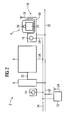
- FIG. 2 shows the same automation system as FIG. 1, in which case the safety-related fieldbus 20 is replaced by a Standard fieldbus 32 replaced without special security features is. For this reason, the emergency stop buttons 14, 16 are not via the fieldbus 32 but via a separately routed Emergency stop circuit 34 connected to each other.
- the emergency stop circuit 34 acts on the machine 6 and can also, as related described with Fig. 1 triggered via the stop button 30 become. Therefore, the radio base station 12 in which the corresponding radio signal is received, connected to the emergency stop circuit 34, to generate the emergency stop signal.
- the communication device 4 is in its assigned Tray 10 is on and is out of order. It There is no radio connection between the antennas 24 and 26, which is why a pressure on the stop button 30 is ineffective. Nevertheless, the situation shown in Fig. 2 offers a according Industry standard permissible arrangement, as in the immediate Near the stop button 30, namely on the housing 18 of the tray 10 of the emergency stop button 16 is located, which is ready for use at any time is. Since the emergency stop button 16 is red-yellow is an operator of the plant also not enticed, in case of danger first on the e.g. gray running stop button 30 to press, but is immediately known to him and memorable red-yellow emergency stop button 16.
- FIG. 2 Another security aspect in Fig. 2 is that e.g. at Shift change is easily controllable, whether the communication device 4 is also inserted in its tray 10. This is above all, therefore, makes sense because of the tray 10 as a rule also a charge of the communication device 4 located in, not shown accumulator takes place and so at the beginning of the layer of the subsequent layer, the communication device 4 recharged and thus ready for use.
Landscapes
- Engineering & Computer Science (AREA)
- Computer Networks & Wireless Communication (AREA)
- Physics & Mathematics (AREA)
- General Physics & Mathematics (AREA)
- Transceivers (AREA)
- Mobile Radio Communication Systems (AREA)
- Selective Calling Equipment (AREA)
- Multi-Process Working Machines And Systems (AREA)
- Radar Systems Or Details Thereof (AREA)
Applications Claiming Priority (2)
| Application Number | Priority Date | Filing Date | Title |
|---|---|---|---|
| DE10344358A DE10344358A1 (de) | 2003-09-24 | 2003-09-24 | Einrichtung zur Kommunikation mit einer Anlage |
| DE10344358 | 2003-09-24 |
Publications (3)
| Publication Number | Publication Date |
|---|---|
| EP1519336A2 true EP1519336A2 (fr) | 2005-03-30 |
| EP1519336A3 EP1519336A3 (fr) | 2007-12-05 |
| EP1519336B1 EP1519336B1 (fr) | 2008-11-19 |
Family
ID=34177928
Family Applications (1)
| Application Number | Title | Priority Date | Filing Date |
|---|---|---|---|
| EP04022550A Expired - Lifetime EP1519336B1 (fr) | 2003-09-24 | 2004-09-22 | Dispositif pour communiquer avec un équipement |
Country Status (3)
| Country | Link |
|---|---|
| EP (1) | EP1519336B1 (fr) |
| AT (1) | ATE414968T1 (fr) |
| DE (2) | DE10344358A1 (fr) |
Cited By (4)
| Publication number | Priority date | Publication date | Assignee | Title |
|---|---|---|---|---|
| WO2008092589A1 (fr) * | 2007-02-01 | 2008-08-07 | Memminger-Iro Gmbh | Système de bus pour l'industrie textile |
| AT510658A1 (de) * | 2010-11-11 | 2012-05-15 | Engel Austria Gmbh | Mobiles bediengerät |
| WO2014095192A1 (fr) | 2012-12-20 | 2014-06-26 | Schneider Electric Industries Sas | Systeme de commande incluant un bouton d'arret d'urgence fixe et un bouton d'arret d'urgence mobile |
| WO2017060018A1 (fr) * | 2015-10-06 | 2017-04-13 | Vega Grieshaber Kg | Appareil de terrain de structure modulaire comprenant un appareil d'affichage/de commande qui comprend un module radio et une alimentation en énergie interne |
Families Citing this family (3)
| Publication number | Priority date | Publication date | Assignee | Title |
|---|---|---|---|---|
| DE102004050908A1 (de) | 2004-10-19 | 2006-05-18 | Siemens Ag | Vorrichtung zur Kommunikation mit einer Anlage |
| AT520695B1 (de) * | 2017-11-27 | 2019-11-15 | Keba Ag | Verfahren zum Betreiben eines Maschinensteuerungssystems sowie entsprechendes Maschinensteuerungssystem |
| DE102023124284A1 (de) * | 2023-09-08 | 2025-03-13 | Ltw Intralogistics Gmbh | Bedienungsstand und Lagersystem |
Family Cites Families (6)
| Publication number | Priority date | Publication date | Assignee | Title |
|---|---|---|---|---|
| JP3618375B2 (ja) * | 1994-09-19 | 2005-02-09 | 株式会社安川電機 | 手持ち操作器 |
| DE19946441A1 (de) * | 1999-09-28 | 2001-04-05 | Siemens Ag | Verfahren, Vorrichtung sowie Verwendung derselben zur drahtlosen Übertragung von digitalen Signalen sowie zur drahtlosen Steuerung einer Maschine |
| SE0101202D0 (sv) * | 2001-04-02 | 2001-04-02 | Abb Ab | Industrial robot |
| AT412176B (de) * | 2001-06-26 | 2004-10-25 | Keba Ag | Tragbare vorrichtung zumindest zur visualisierung von prozessdaten einer maschine, eines roboters oder eines technischen prozesses |
| US20030034897A1 (en) * | 2001-08-20 | 2003-02-20 | Shamoon Charles G. | Thermostat and remote control apparatus |
| WO2003088011A2 (fr) * | 2002-04-12 | 2003-10-23 | Keba Ag | Unite de calcul mobile et dispositif d'extension pour commande de machines industrielles |
-
2003
- 2003-09-24 DE DE10344358A patent/DE10344358A1/de not_active Ceased
-
2004
- 2004-09-22 EP EP04022550A patent/EP1519336B1/fr not_active Expired - Lifetime
- 2004-09-22 AT AT04022550T patent/ATE414968T1/de not_active IP Right Cessation
- 2004-09-22 DE DE502004008475T patent/DE502004008475D1/de not_active Expired - Lifetime
Cited By (13)
| Publication number | Priority date | Publication date | Assignee | Title |
|---|---|---|---|---|
| WO2008092589A1 (fr) * | 2007-02-01 | 2008-08-07 | Memminger-Iro Gmbh | Système de bus pour l'industrie textile |
| AT510658A1 (de) * | 2010-11-11 | 2012-05-15 | Engel Austria Gmbh | Mobiles bediengerät |
| AT13515U1 (de) * | 2010-11-11 | 2014-02-15 | Engel Austria Gmbh | Mobiles Bediengerät |
| US20150351260A1 (en) * | 2012-12-20 | 2015-12-03 | Schneider Electric Industries Sas | Control system including a stationary emergency stop button and a mobile emergency stop button |
| FR3000286A1 (fr) * | 2012-12-20 | 2014-06-27 | Schneider Electric Ind Sas | Systeme de commande incluant un bouton d'arret d'urgence fixe et un bouton d'arret d'urgence mobile |
| CN104871276A (zh) * | 2012-12-20 | 2015-08-26 | 施耐德电器工业公司 | 包括固定紧急停止按钮和移动紧急停止按钮的控制系统 |
| WO2014095192A1 (fr) | 2012-12-20 | 2014-06-26 | Schneider Electric Industries Sas | Systeme de commande incluant un bouton d'arret d'urgence fixe et un bouton d'arret d'urgence mobile |
| JP2016502248A (ja) * | 2012-12-20 | 2016-01-21 | シュネーデル、エレクトリック、インダストリーズ、エスアーエスSchneider Electric Industries Sas | 据置型非常停止ボタンおよび可搬型非常停止ボタンを含む制御システム |
| US9750143B2 (en) | 2012-12-20 | 2017-08-29 | Schneider Electric Industries Sas | Control system including a stationary emergency stop button and a mobile emergency stop button |
| CN104871276B (zh) * | 2012-12-20 | 2017-10-24 | 施耐德电器工业公司 | 包括固定紧急停止按钮和移动紧急停止按钮的控制系统 |
| WO2017060018A1 (fr) * | 2015-10-06 | 2017-04-13 | Vega Grieshaber Kg | Appareil de terrain de structure modulaire comprenant un appareil d'affichage/de commande qui comprend un module radio et une alimentation en énergie interne |
| CN108027598A (zh) * | 2015-10-06 | 2018-05-11 | Vega格里沙贝两合公司 | 模块化的现场设备 |
| US10983494B2 (en) | 2015-10-06 | 2021-04-20 | Vega Grieshaber Kg | Modular field device having a display/operating device containing a radio module and an internal power supply |
Also Published As
| Publication number | Publication date |
|---|---|
| DE502004008475D1 (de) | 2009-01-02 |
| EP1519336A3 (fr) | 2007-12-05 |
| EP1519336B1 (fr) | 2008-11-19 |
| DE10344358A1 (de) | 2005-05-04 |
| ATE414968T1 (de) | 2008-12-15 |
Similar Documents
| Publication | Publication Date | Title |
|---|---|---|
| AT412196B (de) | Verfahren zur zuordnung einer mobilen bedien- und/oder beobachtungseinrichtung zu einer maschine sowie bedien- und/oder beobachtungseinrichtung hierfür | |
| AT412076B (de) | Verfahren zum verbinden mehrerer schweissgeräte sowie schweissgerät hierfür | |
| EP3272467B1 (fr) | Système d'agencement adaptateur | |
| EP2139803B2 (fr) | Procédé pour assurer la commande d'un dispositif de déplacement de charge et commande de dispositif de déplacement de charge | |
| DE102013103454A1 (de) | Messumformerspeisegerät, System zum Einsatz in der Automatisierungstechnik, sowie Verfahren zum Bedienen eines solchen Systems | |
| DE102015226734A1 (de) | Industrielles Gerät und tragbare Vorrichtung | |
| WO2020087101A1 (fr) | Procédé pour faire fonctionner un système de commande de machine et système de commande de machine correspondant | |
| EP1519336B1 (fr) | Dispositif pour communiquer avec un équipement | |
| DE102016121160A1 (de) | Lötanlage | |
| EP3371663B1 (fr) | Système de commande d'installations à commande électrique | |
| EP1665191A1 (fr) | Systeme hmi dote d'un appareil de commande et d'observation mobile pour des commandes de securite d'une installation technique | |
| AT504670B1 (de) | Verfahren zum betreiben einer drahtlosen kommunikationsverbindung zwischen einem mobilen handbediengerät und einer maschinensteuerung sowie entsprechende systemkomponenten | |
| EP2455827A1 (fr) | Appareil de terrain avec un mode de basse consommation qui peut être activé et désactivé au travers des deux interfaces de l' appareil de terrain | |
| DE102004041722A1 (de) | Anordnung zum Laden von mindestens zwei Batterien | |
| EP1665192B1 (fr) | Procede et dispositif de communication avec un systeme | |
| EP1664950B1 (fr) | Dispositif pour communiquer avec un appareil | |
| AT518665A4 (de) | Steuerungssystem für elektrisch gesteuerte Anlagen | |
| EP3582464A1 (fr) | Procédé d'identification de liaison d'un fonctionnement fiable et système de communication | |
| EP1199278B1 (fr) | Machine de travail mobile avec deux pupitres de commande | |
| WO2017072246A1 (fr) | Système de commande pour la commande sécurisée de machines | |
| DE102008037195A1 (de) | Vorrichtung zum Bedienen eines Feldgeräts, das in ein Funknetzwerk der Automatisierungstechnik eingebunden ist | |
| EP1519337B1 (fr) | Procédé et dispositif pour communiquer avec un équipement | |
| EP3058428A1 (fr) | Commande mobile d'installations | |
| DE202019103188U1 (de) | Sicherheitsschaltelement für Maschinen oder Roboter | |
| EP3582032A1 (fr) | Dispositif de terrain à temps d'arrêt réduit lors de la mise à jour du micrologiciel |
Legal Events
| Date | Code | Title | Description |
|---|---|---|---|
| PUAI | Public reference made under article 153(3) epc to a published international application that has entered the european phase |
Free format text: ORIGINAL CODE: 0009012 |
|
| AK | Designated contracting states |
Kind code of ref document: A2 Designated state(s): AT BE BG CH CY CZ DE DK EE ES FI FR GB GR HU IE IT LI LU MC NL PL PT RO SE SI SK TR |
|
| AX | Request for extension of the european patent |
Extension state: AL HR LT LV MK |
|
| PUAL | Search report despatched |
Free format text: ORIGINAL CODE: 0009013 |
|
| AK | Designated contracting states |
Kind code of ref document: A3 Designated state(s): AT BE BG CH CY CZ DE DK EE ES FI FR GB GR HU IE IT LI LU MC NL PL PT RO SE SI SK TR |
|
| AX | Request for extension of the european patent |
Extension state: AL HR LT LV MK |
|
| 17P | Request for examination filed |
Effective date: 20080312 |
|
| GRAP | Despatch of communication of intention to grant a patent |
Free format text: ORIGINAL CODE: EPIDOSNIGR1 |
|
| AKX | Designation fees paid |
Designated state(s): AT BE BG CH CY CZ DE DK EE ES FI FR GB GR HU IE IT LI LU MC NL PL PT RO SE SI SK TR |
|
| GRAS | Grant fee paid |
Free format text: ORIGINAL CODE: EPIDOSNIGR3 |
|
| GRAA | (expected) grant |
Free format text: ORIGINAL CODE: 0009210 |
|
| AK | Designated contracting states |
Kind code of ref document: B1 Designated state(s): AT BE BG CH CY CZ DE DK EE ES FI FR GB GR HU IE IT LI LU MC NL PL PT RO SE SI SK TR |
|
| REG | Reference to a national code |
Ref country code: GB Ref legal event code: FG4D Free format text: NOT ENGLISH |
|
| REG | Reference to a national code |
Ref country code: CH Ref legal event code: EP |
|
| REG | Reference to a national code |
Ref country code: IE Ref legal event code: FG4D Free format text: LANGUAGE OF EP DOCUMENT: GERMAN |
|
| REF | Corresponds to: |
Ref document number: 502004008475 Country of ref document: DE Date of ref document: 20090102 Kind code of ref document: P |
|
| PG25 | Lapsed in a contracting state [announced via postgrant information from national office to epo] |
Ref country code: ES Free format text: LAPSE BECAUSE OF FAILURE TO SUBMIT A TRANSLATION OF THE DESCRIPTION OR TO PAY THE FEE WITHIN THE PRESCRIBED TIME-LIMIT Effective date: 20090301 |
|
| NLV1 | Nl: lapsed or annulled due to failure to fulfill the requirements of art. 29p and 29m of the patents act | ||
| PG25 | Lapsed in a contracting state [announced via postgrant information from national office to epo] |
Ref country code: PL Free format text: LAPSE BECAUSE OF FAILURE TO SUBMIT A TRANSLATION OF THE DESCRIPTION OR TO PAY THE FEE WITHIN THE PRESCRIBED TIME-LIMIT Effective date: 20081119 Ref country code: FI Free format text: LAPSE BECAUSE OF FAILURE TO SUBMIT A TRANSLATION OF THE DESCRIPTION OR TO PAY THE FEE WITHIN THE PRESCRIBED TIME-LIMIT Effective date: 20081119 Ref country code: SI Free format text: LAPSE BECAUSE OF FAILURE TO SUBMIT A TRANSLATION OF THE DESCRIPTION OR TO PAY THE FEE WITHIN THE PRESCRIBED TIME-LIMIT Effective date: 20081119 Ref country code: NL Free format text: LAPSE BECAUSE OF FAILURE TO SUBMIT A TRANSLATION OF THE DESCRIPTION OR TO PAY THE FEE WITHIN THE PRESCRIBED TIME-LIMIT Effective date: 20081119 |
|
| REG | Reference to a national code |
Ref country code: IE Ref legal event code: FD4D |
|
| PG25 | Lapsed in a contracting state [announced via postgrant information from national office to epo] |
Ref country code: DK Free format text: LAPSE BECAUSE OF FAILURE TO SUBMIT A TRANSLATION OF THE DESCRIPTION OR TO PAY THE FEE WITHIN THE PRESCRIBED TIME-LIMIT Effective date: 20081119 Ref country code: RO Free format text: LAPSE BECAUSE OF FAILURE TO SUBMIT A TRANSLATION OF THE DESCRIPTION OR TO PAY THE FEE WITHIN THE PRESCRIBED TIME-LIMIT Effective date: 20081119 Ref country code: BG Free format text: LAPSE BECAUSE OF FAILURE TO SUBMIT A TRANSLATION OF THE DESCRIPTION OR TO PAY THE FEE WITHIN THE PRESCRIBED TIME-LIMIT Effective date: 20090219 Ref country code: EE Free format text: LAPSE BECAUSE OF FAILURE TO SUBMIT A TRANSLATION OF THE DESCRIPTION OR TO PAY THE FEE WITHIN THE PRESCRIBED TIME-LIMIT Effective date: 20081119 Ref country code: IE Free format text: LAPSE BECAUSE OF FAILURE TO SUBMIT A TRANSLATION OF THE DESCRIPTION OR TO PAY THE FEE WITHIN THE PRESCRIBED TIME-LIMIT Effective date: 20081119 |
|
| PG25 | Lapsed in a contracting state [announced via postgrant information from national office to epo] |
Ref country code: PT Free format text: LAPSE BECAUSE OF FAILURE TO SUBMIT A TRANSLATION OF THE DESCRIPTION OR TO PAY THE FEE WITHIN THE PRESCRIBED TIME-LIMIT Effective date: 20090420 Ref country code: SE Free format text: LAPSE BECAUSE OF FAILURE TO SUBMIT A TRANSLATION OF THE DESCRIPTION OR TO PAY THE FEE WITHIN THE PRESCRIBED TIME-LIMIT Effective date: 20090219 Ref country code: CZ Free format text: LAPSE BECAUSE OF FAILURE TO SUBMIT A TRANSLATION OF THE DESCRIPTION OR TO PAY THE FEE WITHIN THE PRESCRIBED TIME-LIMIT Effective date: 20081119 |
|
| PLBE | No opposition filed within time limit |
Free format text: ORIGINAL CODE: 0009261 |
|
| STAA | Information on the status of an ep patent application or granted ep patent |
Free format text: STATUS: NO OPPOSITION FILED WITHIN TIME LIMIT |
|
| PG25 | Lapsed in a contracting state [announced via postgrant information from national office to epo] |
Ref country code: SK Free format text: LAPSE BECAUSE OF FAILURE TO SUBMIT A TRANSLATION OF THE DESCRIPTION OR TO PAY THE FEE WITHIN THE PRESCRIBED TIME-LIMIT Effective date: 20081119 |
|
| 26N | No opposition filed |
Effective date: 20090820 |
|
| BERE | Be: lapsed |
Owner name: SIEMENS A.G. Effective date: 20090930 |
|
| PG25 | Lapsed in a contracting state [announced via postgrant information from national office to epo] |
Ref country code: MC Free format text: LAPSE BECAUSE OF NON-PAYMENT OF DUE FEES Effective date: 20090930 |
|
| REG | Reference to a national code |
Ref country code: CH Ref legal event code: PL |
|
| PG25 | Lapsed in a contracting state [announced via postgrant information from national office to epo] |
Ref country code: BE Free format text: LAPSE BECAUSE OF NON-PAYMENT OF DUE FEES Effective date: 20090930 |
|
| PG25 | Lapsed in a contracting state [announced via postgrant information from national office to epo] |
Ref country code: GR Free format text: LAPSE BECAUSE OF FAILURE TO SUBMIT A TRANSLATION OF THE DESCRIPTION OR TO PAY THE FEE WITHIN THE PRESCRIBED TIME-LIMIT Effective date: 20090220 Ref country code: LI Free format text: LAPSE BECAUSE OF NON-PAYMENT OF DUE FEES Effective date: 20090930 Ref country code: CH Free format text: LAPSE BECAUSE OF NON-PAYMENT OF DUE FEES Effective date: 20090930 |
|
| PG25 | Lapsed in a contracting state [announced via postgrant information from national office to epo] |
Ref country code: AT Free format text: LAPSE BECAUSE OF NON-PAYMENT OF DUE FEES Effective date: 20090922 |
|
| PG25 | Lapsed in a contracting state [announced via postgrant information from national office to epo] |
Ref country code: LU Free format text: LAPSE BECAUSE OF NON-PAYMENT OF DUE FEES Effective date: 20090922 |
|
| PG25 | Lapsed in a contracting state [announced via postgrant information from national office to epo] |
Ref country code: HU Free format text: LAPSE BECAUSE OF FAILURE TO SUBMIT A TRANSLATION OF THE DESCRIPTION OR TO PAY THE FEE WITHIN THE PRESCRIBED TIME-LIMIT Effective date: 20090520 |
|
| PG25 | Lapsed in a contracting state [announced via postgrant information from national office to epo] |
Ref country code: TR Free format text: LAPSE BECAUSE OF FAILURE TO SUBMIT A TRANSLATION OF THE DESCRIPTION OR TO PAY THE FEE WITHIN THE PRESCRIBED TIME-LIMIT Effective date: 20081119 |
|
| PG25 | Lapsed in a contracting state [announced via postgrant information from national office to epo] |
Ref country code: CY Free format text: LAPSE BECAUSE OF FAILURE TO SUBMIT A TRANSLATION OF THE DESCRIPTION OR TO PAY THE FEE WITHIN THE PRESCRIBED TIME-LIMIT Effective date: 20081119 |
|
| REG | Reference to a national code |
Ref country code: FR Ref legal event code: PLFP Year of fee payment: 13 |
|
| REG | Reference to a national code |
Ref country code: FR Ref legal event code: PLFP Year of fee payment: 14 |
|
| REG | Reference to a national code |
Ref country code: FR Ref legal event code: PLFP Year of fee payment: 15 |
|
| PGFP | Annual fee paid to national office [announced via postgrant information from national office to epo] |
Ref country code: DE Payment date: 20181119 Year of fee payment: 15 |
|
| PGFP | Annual fee paid to national office [announced via postgrant information from national office to epo] |
Ref country code: FR Payment date: 20190918 Year of fee payment: 16 |
|
| PGFP | Annual fee paid to national office [announced via postgrant information from national office to epo] |
Ref country code: GB Payment date: 20190902 Year of fee payment: 16 |
|
| PGFP | Annual fee paid to national office [announced via postgrant information from national office to epo] |
Ref country code: IT Payment date: 20190926 Year of fee payment: 16 |
|
| REG | Reference to a national code |
Ref country code: DE Ref legal event code: R119 Ref document number: 502004008475 Country of ref document: DE |
|
| PG25 | Lapsed in a contracting state [announced via postgrant information from national office to epo] |
Ref country code: DE Free format text: LAPSE BECAUSE OF NON-PAYMENT OF DUE FEES Effective date: 20200401 |
|
| GBPC | Gb: european patent ceased through non-payment of renewal fee |
Effective date: 20200922 |
|
| PG25 | Lapsed in a contracting state [announced via postgrant information from national office to epo] |
Ref country code: FR Free format text: LAPSE BECAUSE OF NON-PAYMENT OF DUE FEES Effective date: 20200930 |
|
| PG25 | Lapsed in a contracting state [announced via postgrant information from national office to epo] |
Ref country code: GB Free format text: LAPSE BECAUSE OF NON-PAYMENT OF DUE FEES Effective date: 20200922 |
|
| PG25 | Lapsed in a contracting state [announced via postgrant information from national office to epo] |
Ref country code: IT Free format text: LAPSE BECAUSE OF NON-PAYMENT OF DUE FEES Effective date: 20200922 |