EP1519372A2 - Système et méthode pour obtenir une précision positionelle d'un robot de bibliothèque en utilisant une vision parallaxe - Google Patents
Système et méthode pour obtenir une précision positionelle d'un robot de bibliothèque en utilisant une vision parallaxe Download PDFInfo
- Publication number
- EP1519372A2 EP1519372A2 EP04255877A EP04255877A EP1519372A2 EP 1519372 A2 EP1519372 A2 EP 1519372A2 EP 04255877 A EP04255877 A EP 04255877A EP 04255877 A EP04255877 A EP 04255877A EP 1519372 A2 EP1519372 A2 EP 1519372A2
- Authority
- EP
- European Patent Office
- Prior art keywords
- sensor
- calibration mark
- distance
- storage
- calibration
- Prior art date
- Legal status (The legal status is an assumption and is not a legal conclusion. Google has not performed a legal analysis and makes no representation as to the accuracy of the status listed.)
- Granted
Links
Images




Classifications
-
- B—PERFORMING OPERATIONS; TRANSPORTING
- B25—HAND TOOLS; PORTABLE POWER-DRIVEN TOOLS; MANIPULATORS
- B25J—MANIPULATORS; CHAMBERS PROVIDED WITH MANIPULATION DEVICES
- B25J9/00—Program-controlled manipulators
- B25J9/16—Program controls
- B25J9/1679—Program controls characterised by the tasks executed
- B25J9/1692—Calibration of manipulator
-
- G—PHYSICS
- G11—INFORMATION STORAGE
- G11B—INFORMATION STORAGE BASED ON RELATIVE MOVEMENT BETWEEN RECORD CARRIER AND TRANSDUCER
- G11B15/00—Driving, starting or stopping record carriers of filamentary or web form; Driving both such record carriers and heads; Guiding such record carriers or containers therefor; Control thereof; Control of operating function
- G11B15/675—Guiding containers, e.g. loading, ejecting cassettes
- G11B15/68—Automatic cassette changing arrangements; automatic tape changing arrangements
- G11B15/6895—Automatic tape changing arrangements
-
- G—PHYSICS
- G11—INFORMATION STORAGE
- G11B—INFORMATION STORAGE BASED ON RELATIVE MOVEMENT BETWEEN RECORD CARRIER AND TRANSDUCER
- G11B17/00—Guiding record carriers not specifically of filamentary or web form, or of supports therefor
- G11B17/22—Guiding record carriers not specifically of filamentary or web form, or of supports therefor from random access magazine of disc records
- G11B17/228—Control systems for magazines
-
- G—PHYSICS
- G05—CONTROLLING; REGULATING
- G05B—CONTROL OR REGULATING SYSTEMS IN GENERAL; FUNCTIONAL ELEMENTS OF SUCH SYSTEMS; MONITORING OR TESTING ARRANGEMENTS FOR SUCH SYSTEMS OR ELEMENTS
- G05B2219/00—Program-control systems
- G05B2219/30—Nc systems
- G05B2219/37—Measurements
- G05B2219/37067—Calibrate work surface, reference markings on object, work surface
-
- G—PHYSICS
- G05—CONTROLLING; REGULATING
- G05B—CONTROL OR REGULATING SYSTEMS IN GENERAL; FUNCTIONAL ELEMENTS OF SUCH SYSTEMS; MONITORING OR TESTING ARRANGEMENTS FOR SUCH SYSTEMS OR ELEMENTS
- G05B2219/00—Program-control systems
- G05B2219/30—Nc systems
- G05B2219/39—Robotics, robotics to robotics hand
- G05B2219/39024—Calibration of manipulator
-
- G—PHYSICS
- G05—CONTROLLING; REGULATING
- G05B—CONTROL OR REGULATING SYSTEMS IN GENERAL; FUNCTIONAL ELEMENTS OF SUCH SYSTEMS; MONITORING OR TESTING ARRANGEMENTS FOR SUCH SYSTEMS OR ELEMENTS
- G05B2219/00—Program-control systems
- G05B2219/30—Nc systems
- G05B2219/39—Robotics, robotics to robotics hand
- G05B2219/39045—Camera on end effector detects reference pattern
-
- G—PHYSICS
- G05—CONTROLLING; REGULATING
- G05B—CONTROL OR REGULATING SYSTEMS IN GENERAL; FUNCTIONAL ELEMENTS OF SUCH SYSTEMS; MONITORING OR TESTING ARRANGEMENTS FOR SUCH SYSTEMS OR ELEMENTS
- G05B2219/00—Program-control systems
- G05B2219/30—Nc systems
- G05B2219/45—Nc applications
- G05B2219/45045—Maintenance, automatic storage and retrieval system
Definitions
- the present invention relates generally to automated storage libraries for storing and retrieving computer data, and more particularly to systems and methods for improving the positional accuracy of library robotics through the use of parallax viewing techniques.
- Automated storage library systems typically include a plurality of storage media devices, a transport mechanism, and one or more storage media drives in communication with a computer system or network for inputting and outputting desired information to and from the plurality of storage media devices.
- Magnetic tape cartridges for example, have proven to be an efficient and effective medium for data storage in computer systems and storage libraries.
- Automated tape cartridge libraries generally have a plurality of storage bins or slots for storing tape cartridges, a robotic picker mechanism (often referred to as a "picker"), and one or more tape drives.
- the robotic picker may be controlled to select a specific storage tape cartridge from the library and transfer the tape cartridge between a storage slot and a tape drive within seconds.
- the robotic picker typically includes a gripper or hand mechanism positioned on the robotic picker.
- the robotic picker may position the gripper near a desired tape cartridge such that the gripper may grip the tape cartridge to remove the tape cartridge from the storage bin and transfer the tape cartridge to load the tape cartridge into a tape drive, load port (for adding or removing tapes from the library), or the like.
- An automated storage library is typically interfaced to a computer system such as a computer network or the like.
- the storage library or interfaced computer system may index the location of the tape cartridges and their associated stored data within the storage library for later retrieval of the stored information.
- the storage library may be activated to retrieve a desired storage tape and load it into a drive to access the stored information and/or write new information.
- multiple tape drives are generally employed to improve access and storage performance by operating in parallel as well as providing back-up drives in case of failure, maintenance, and the like.
- the positional accuracy of the robotic mechanism in relation to the storage bins and tape drives is desirably maintained to a high degree to reduce the potential for wear and damage to the cartridges, storage bins, and tape drives.
- inaccurate positioning may cause mating surfaces between storage cartridge, storage bins, and tape drives to rub or collide causing damage to one or more.
- wear and collisions may cause undesirable debris within the automated library housing that may interfere with or degrade, for example, the tape drive operation.
- Positional accuracy of the robotic mechanism may be determined with an optical scanner that scans a point of light in x and y directions, e.g., horizontally and vertically, across a target or fiducial mark on a storage bin or drive bezel. If the camera is positioned such that the target falls within the camera's field of vision, the x and y coordinate values may be measured directly. The distance in the z direction, the extension or depth of the target from the camera, however, is not directly measured by the camera. The distance or z coordinate value can be inferred from a combination of other measurable and/or previously known quantities. For example, the distance may be determined by comparing the image or apparent size of the target to the known size of the target.
- One problem with conventional optical approaches for determining the distance between a robotic picker mechanism and portion of the library including a calibration mark is that the target size generally must be known. Additionally, if the calibration mark size is only approximately known, e.g., known within a certain variance, the distance measurement suffers in proportion to the variance of the calibration mark size.
- a method includes detecting a calibration mark associated with a storage library from a first position and from a second position, where the first position and the second position are separated by a known distance. Further, the method includes determining a shift in the detected calibration mark between the first position and the second position by using at least one sensor, e.g., a camera, and determining a distance between a reference position and the calibration mark based on the apparent shift in the calibration mark, the offset distance of the sensor, and a focal length of the camera.
- at least one sensor e.g., a camera
- the system includes a gripper assembly for handling storage devices, a sensor associated with the gripper assembly; and a controller.
- the controller and sensor are adapted to detect a calibration mark from a first position and detect a calibration mark from a second position.
- the controller and sensor are further adapted to determine a "perspective" shift in the detected calibration mark from the first position and the second position relative to the sensor, and thereby determine a distance between the gripper assembly and the calibration mark based on the shift in the apparent position of the detected calibration mark, the distance between the first position and the second position (e.g., the viewing positions), and the focal length associated with the sensor.
- Figure 1 illustrates an exemplary automated tape library system having a transport mechanism
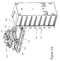
- Figures 2A and 2B illustrate perspective views of an exemplary gripper assembly and sensor adjacent a column of storage slots
- Figure 3 illustrates an exemplary camera including an area sensor
- Figures 4A-4F illustrate various exemplary fiducial marks or calibration marks
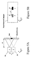
- Figures 5A and 5B illustrate an exemplary operation of a sensor to determine a distance between a sensor and a calibration mark
- Figure 6 illustrates an exemplary method for determining a distance between a sensor and a calibration mark.
- a sensor for positional accuracy of an automated storage library robotics assembly includes an area scanner such as a Charge Coupled Device (CCD) or Complementary Metal Oxide Semiconductor (CMOS) device to detect a calibration mark or other fiducial associated with a storage bin or drive bezel and position the robotics correctly for a pick or place operation.
- CCD Charge Coupled Device
- CMOS Complementary Metal Oxide Semiconductor
- Increased accuracy of distance measurement between the robotics assembly and storage bin or drive bezel may be determined through parallax viewing methods. For example, multiple two-dimensional images of a calibration mark or fiducial associated with a storage bin or drive bezel may be detected at slightly different sensor positions and a shift in the calibration mark between the two detected positions determined. With knowledge of the difference in sensor positions and the focal length of the sensor, the distance from the sensor to the calibration mark may be determined.
- the exemplary parallax viewing methods allow the creation of relatively large virtual calibration marks from smaller actual calibration marks, where a larger virtual calibration mark may increase the accuracy of distance measurements. Further, distances to fiducials of approximate, unknown, or small size may generally be measured with greater accuracy than by single image methods.
- FIG 1 illustrates an exemplary automated storage library system 100 for the storage and retrieval of a plurality of tape cartridges 14.
- Storage library system 100 may be used with the systems and methods described below with reference to Figures 2A-6 .
- the library system 100 is presented merely as an exemplary library system useful with the methods and systems described herein, and various other library systems and configurations may be used. It should also be understood that the various examples are contemplated for use with other types of storage media devices and storage media libraries useful for storing data.
- a storage library may include various storage devices such as magnetic disks, optical storage devices, and the like alone or in combination with other data storage devices.
- Storage library system 100 includes one or more tape drives 12, a plurality of storage cartridges 14 stored in bins or storage slots 16, and a robotic arm 18 equipped with a gripper mechanism 20 for transporting selected cartridges 14.
- robotics including robotic arm 18 and gripper 20 transport tape cartridges 14 between storage slots 16 and tape drives 12.
- Tape drives 12 are controlled by library controller 4, which is in communication with a host computer or network system 40.
- An exemplary drive 12 includes the SDLTTM 320 magnetic tape drive
- an exemplary storage cartridge 14 includes the Super DLTapeTM Type I storage cartridge both sold by Quantum Corporation. It should be clear, however, that any type of removable data storage medium and any type of data media drive or data transfer device useful for such a storage medium may be used within storage library 100.
- a calibration process is performed to identify and store relative positions of various features within the library system such that robotic arm 18 may navigate within the library system 100.
- positional calibration is performed with storage slots 16 and tape drives 12.
- the library system 100 includes a sensor 50 associated with the gripper mechanism 20 that may detect a calibration mark or suitable calibration fiducial mark associated with one or more storage slots 16 and/or tape drives 12. Sensor 50 may detect the calibration mark from at least two different positions and use various parallax viewing methods to determine positional information of gripper mechanisms 20 as described below.
- sensor 50 includes a CMOS or CCD area scanner, but may include any suitable image sensor.
- sensors such as a line scanner or mechanical barcode scanner may be used to produce a suitable two-dimensional image.
- a CMOS area scanner e.g., may provide greater accuracy and faster movement within the library.
- a calibration table may be created during use as sensor 50 moves to previously unused positions.
- Sensor 50 may be mounted on the gripper mechanism 20 or the robotic arm 18 in any suitable manner.
- sensor 50 is located adjacent the gripper mechanism 20 (as shown in Figures 2A and 2B ) and may be suitably oriented to face the expected position of a calibration mark.
- the sensor 50 could be located on any convenient location on the gripper mechanism 20 or robotic arm 18.
- the library system 100 further includes a library controller 4 for coordinating movements and actions of drives 12, robotic arm 18, gripper mechanism 20, sensor 50, and the like.
- Library controller 4 may include any suitable computer processor and is typically interconnected with a host processor (not shown), which sends access commands to controller 4. In this manner, information to be recorded or read from one or more of the cartridges 14 is transmitted between one of drives 12 and the host processor, for example, through controller 4 or a separate data path.
- Library controller 4 may include any programmable general purpose computer or processor and preferably will have a suitably programmed microprocessor or microcontroller.
- the input-output connections between the library controller and various other components of the library system 100 may include well-known industry standard cabling and communication protocols. For example, Ethernet, Inter Integrated Circuit bus (I2C), Small Computer System Interface (SCSI), ultra-wide SCSI, fast SCSI, fibre channel, and the like.
- Controller 4 operates to coordinate movements and actions of media drives 12, robotic arm 18, and the like.
- Controller 4 may include a suitable processor as described above and is typically interconnected with a host processor, which sends access commands to controller 4.
- information recorded to or read from one or more of the cartridges 14 is transmitted between one of the drives 12 to the host or a storage area network through a second data path connection, e.g., a fibre channel bridge or the like.
- Automated tape library system 100 may further include various other features such as a barcode scanner, load ports for manually adding and removing cartridges to and from the library, various access doors, control panels, and the like as are known in the art. For clarity, however, such additional features have been omitted from the description.
- Figures 2A and 2B illustrate more detailed views of a robotic picker assembly including an exemplary gripper mechanism 220 and sensor 250 adjacent a column of storage slots 216 having a calibration mark 200 thereon (seen in Figure 2B ).
- the library system may include any number of storage slots 216 arranged in various manners. Typically, multiple columns of storage slots 216 are arranged along an interior cabinet that may be, for example, rectangular or cylindrical in shape.
- the configuration of storage slots may influence the position and orientation of calibration mark 200.
- storage slots 216 may be angled down from a front opening to the back to more securely hold cartridges 214 and a calibration mark 200 may therefore face or be detectable from a similar angle as the slots.
- a calibration mark 200 may be associated with one or more storage slots 216, e.g., a single calibration mark 200 may be used to calibrate for a group or pack of adjacent storage slots 216.
- Calibration mark 200 may include any suitable target shape such as a rectangle, cross-hair, or other fiducial mark as illustrated in Figures 4A-4F as 450a through 450e. Calibration mark 200 may further include a raised portion, sunken portion, coplanar or otherwise formed features. Alternatively, sensor 250 may use a feature of a storage bin or drive bezel that is suitable to image with sensor 250, i.e., a specific calibration mark dedicated for calibration/positional purposes is not necessary. Thus, calibration mark 200 may include any fiducial element capable of providing a positional reference, e.g., an intentional mark such as a cross or merely a functional element associated with a drive, storage bin, or the like. Additionally, an unintentional mark may also be used.
- a fiducial element capable of providing a positional reference, e.g., an intentional mark such as a cross or merely a functional element associated with a drive, storage bin, or the like. Additionally, an unintentional mark may also be used.
- light source 240 provides illumination and sensor 250 is oriented towards the expected position of target 200.
- light source 240 may be optional.
- light source 240 may include an infrared light source in conjunction with a suitable camera that can detect infrared light.
- Light source 240 may also provide illumination for a barcode sensor 230 or other identifying sensor.
- Optics included in camera 250 may create a depth of focus at or near the expected location of calibration mark 200.
- the depth of focus is within 1.0 inches of the expected depth of calibration mark 200.
- sensor 250 is adapted to include a depth of focus approximately plus/minus 0.5 to 1.0 inches from the expected distance of the calibration mark 200 from sensor 250 during operation.
- an auto-focus camera may be included if the variable focal length is known or can be determined.
- FIG. 3 A more detailed view of an exemplary sensor 350 including a lens 352 and imaging device (not shown) for detecting calibration marks and determining robotics positioning accuracy is illustrated in Figure 3 , which may be referred to in conjunction with Figures 2A and 2B.
- Sensor 350 includes a lens 352 to focus and image the calibration mark or fiducial onto a suitable imaging device.
- sensor 50 includes a relatively small CCD or CMOS camera subsystem, e.g., a CMOS 640 by 480 pixel array, with a fixed focal length lens 352 mounted upon moveable robotic arm 218 in a tape library system. That is, sensor 350 may travel along with the robotic arm 218 in all its dimensions of freedom.
- Alternative examples may include, but do not require, a variable focal length lens and/or a separate means of repositioning the camera for parallax viewing.
- multiple sensors may be used to detect calibration mark 200 from different positions or vantage points.
- Sensor 350 may further include various mirrors and lenses to project and focus the calibration mark 200 to an area scanner chip depending on the application and design of sensor 350.
- a mirror (not shown) is used to redirect the image towards the base of camera 350 where an area scanner is located thereby reducing the profile of sensor 350.
- camera 350 and gripper mechanism may be in various configurations depending on the particular application and design considerations.
- camera 350 may be located below, horizontally adjacent to, or angled with respect to the gripper mechanism.
- a single image method for camera based distance measurements includes comparing an apparent object size (s'), i.e., the dimensions of the calibration or fiducial as detected, to an actual object size (s) of the object, i.e., the actual dimensions of the calibration mark or fiducial, to determine a relative distance (d) from the camera to the object.
- s' apparent object size
- s actual object size
- d relative distance
- the actual size of the calibration mark (s) is known. Even in instances where the calibration mark size is approximately known, the distance measurement suffers uncertainty in proportion to the variance of the calibration mark size. Further, the resolution of typical CCD and CMOS camera technology is bounded at some practical limit because the camera includes a grid of individual pixels with a finite size. The result is that the sensitivity of the distance measurement becomes inversely proportional to the size of the calibration mark itself. For example, consider the apparent size of a small point-like fiducial, on the order of the camera pixel dimensions - the perceived size of such a fiducial will not vary greatly over the range of interest because approximately the same number of pixels will be illuminated at varying distances.
- a sensor acquires multiple, e.g., two or more, images of a desired calibration mark or fiducial mark from slightly different vantage points or positions in order to create a larger virtual fiducial.
- the exemplary method may further provide increased accuracy of distance measurements.
- a calibration mark may include any suitable fiducial such as a line, point, shape, or the like that may be used as a point of reference for the sensor and associated robotic picker mechanism.
- a sensor is slightly offset in the horizontal or vertical direction, orthogonal to the direction between the sensor and the calibration mark.
- the robot may position itself such that the calibration mark is within the field of view and the horizontal and vertical axes form a plane orthogonal with the sensor's line of sight to the calibration mark.
- the relative position of the calibration mark to the sensor is detected and the sensor is then moved (e.g., via the robot) to a second, slightly offset, position still within the field of view of the sensor.
- a second position of the calibration mark is acquired from the new sensor position.
- the movement of the sensor will result in a shift in the apparent position of the calibration mark location between the two detections that is a direct function of the calibration mark distance and the lens magnification, and because the magnification of the lens may be known or determined, the distance to the calibration mark may be calculated.
- the calculations and distances are determined by the library and/or gripper controller through firmware, software, or hardware, alone or in any combination. In other examples, the host may determine the distance measurements.
- FIGS 5A and 5B illustrate an exemplary operation of sensor 50 and detected positions of calibration marks 500 relative to sensor 50.
- Calibration mark 500 may be associated with a storage bin, drive bezel, or the like as shown and may include any suitable fiducial.
- Sensor 50 detects calibration mark 500 from a first position 1 shown as image 1, and detects calibration mark 500 from a second position 2 (illustrated in dotted lines) shown as image 2, where the first position 1 and second position 2 are offset a distance s.
- two separate sensors e.g., at positions 1 and 2 may detect relative positions of calibration mark 500, e.g., images 1 and 2.
- Figure 5B illustrates the difference between the detected calibration marks 500 detected by sensor 50, where p and p' represent the positions of the fiducial center in the original position 1 and "shifted" position 2 respectively.
- the position of sensor 50 is translated to a second position substantially orthogonal to the distance between sensor 50 and the calibration mark 500.
- the translation of sensor 50 to the second position will produce a perspective shift in the detection of calibration mark 500.
- the perspective shift in position, p - p' is similar to the apparent size s' (as described above), and the distance moved by the robot to create the shifted image is similar to s (the actual calibration mark size), which may be known or determined.
- f the focal length of the camera
- d the distance of the average position of the camera.
- Figure 6 illustrates, an exemplary method of determining the distance between a sensor and a calibration mark.
- a sensor associated with a robotic mechanism is positioned to detect a calibration mark.
- the sensor may first search for a calibration mark if necessary, however, generally a system controller will have approximate coordinates of the location of a calibration mark and will position accordingly.
- the sensor may detect a relative position of the calibration mark with respect to the sensor in an x and y direction, e.g., horizontal and vertical.
- the robotic assembly and/or sensor may be repositioned, e.g., translated, to a second position.
- the distance between the first position and second position may vary depending on the particular application and desired accuracy of the measurements.
- the calibration mark is then detected from the second position in block 630.
- the robotic assembly may include two or more sensors that may detect multiple images from different positions with out translating the robotic assembly.
- the relative shift between the detected calibration mark from the first position and the second position is determined.
- the calibration mark and shift between the first position and the second position may be analyzed by any suitable methods, e.g., a suitable programmed microcontroller or the like.
- the library controller determines the number of pixels between a common feature of the calibration mark to determine the shift between the first position and the second position.
- the distance between the plane including the two sensor positions and the calibration mark may be determined.
- the distance may be determined, e.g., as described above.
- the value s, the distance the sensor is offset between detecting the calibration target at a first position and a second position may be chosen or determined precisely, and does not depend upon a previously known reference value or a real physical fiducial size.
- the quantity (p - p'), the shift the detected position of the calibration target may be considered to be the size of a virtual fiducial that is created by the movement of the robot and/or sensor.
- the sensitivity of the distance measurement is generally proportional to the size of the fiducial, greater accuracy may be obtained by increasing the quantity (p-p'). This may be particularly advantageous for relatively small fiducials, e.g., on the order of the camera pixel size.
- the exemplary methods described, including multiple images, may rely on the center point or other common point of the fiducial in each image and not the fiducial size itself. Variations in the actual fiducial size generally do not affect the accuracy of the distance measurement to the extent it might in single image methods. Therefore, the virtual fiducial size remains relatively well known and preferably within the positioning accuracy limits of the robot system.
Landscapes
- Engineering & Computer Science (AREA)
- Robotics (AREA)
- Mechanical Engineering (AREA)
- Length Measuring Devices By Optical Means (AREA)
- Automatic Tape Cassette Changers (AREA)
- Manipulator (AREA)
Applications Claiming Priority (4)
| Application Number | Priority Date | Filing Date | Title |
|---|---|---|---|
| US50741403P | 2003-09-29 | 2003-09-29 | |
| US507414P | 2003-09-29 | ||
| US10/676,567 US7117068B2 (en) | 2003-09-29 | 2003-09-30 | System and method for library robotics positional accuracy using parallax viewing |
| US676567 | 2003-09-30 |
Publications (3)
| Publication Number | Publication Date |
|---|---|
| EP1519372A2 true EP1519372A2 (fr) | 2005-03-30 |
| EP1519372A3 EP1519372A3 (fr) | 2007-10-31 |
| EP1519372B1 EP1519372B1 (fr) | 2009-01-28 |
Family
ID=34198329
Family Applications (1)
| Application Number | Title | Priority Date | Filing Date |
|---|---|---|---|
| EP04255877A Expired - Lifetime EP1519372B1 (fr) | 2003-09-29 | 2004-09-27 | Système et méthode pour obtenir une précision positionelle d'un robot de bibliothèque en utilisant une vision parallaxe |
Country Status (4)
| Country | Link |
|---|---|
| US (1) | US7117068B2 (fr) |
| EP (1) | EP1519372B1 (fr) |
| JP (1) | JP2005108414A (fr) |
| DE (1) | DE602004019264D1 (fr) |
Cited By (4)
| Publication number | Priority date | Publication date | Assignee | Title |
|---|---|---|---|---|
| EP1967925A1 (fr) * | 2007-03-06 | 2008-09-10 | Interglass Technology AG | Unité de stockage |
| US8134800B2 (en) | 2008-03-12 | 2012-03-13 | Nec Embedded Products, Ltd. | Stop position adjusting device and stop position adjusting method for accessor mechanism |
| EP2584418A1 (fr) * | 2011-10-21 | 2013-04-24 | Siemens Aktiengesellschaft | Procédé et dispositif de localisation d'un point de préhension d'un objet dans une installation |
| CN113927629A (zh) * | 2021-11-16 | 2022-01-14 | 国网湖南省电力有限公司 | 一种连续体机械臂角度传感器标定系统及标定方法 |
Families Citing this family (36)
| Publication number | Priority date | Publication date | Assignee | Title |
|---|---|---|---|---|
| US7533393B2 (en) * | 2003-10-30 | 2009-05-12 | Tandberg Data Asa | Robotics for a data storage system |
| DE102004026814A1 (de) * | 2004-06-02 | 2005-12-29 | Kuka Roboter Gmbh | Verfahren und Vorrichtung zum Verbessern der Positioniergenauigkeit eines Handhabungsgeräts |
| US7206667B2 (en) * | 2004-06-18 | 2007-04-17 | Siemens Medical Solutions Diagnostics | Robot alignment system and method |
| JP4573105B2 (ja) * | 2004-12-10 | 2010-11-04 | 株式会社ダイフク | 物品搬送装置 |
| EP1854037B1 (fr) * | 2005-02-25 | 2014-12-31 | Abb Research Ltd. | Procede et dispositif d'apprentissage de trajectoire automatique |
| US9330246B2 (en) * | 2005-11-09 | 2016-05-03 | Paul J. Munyon | System and method for inhibiting access to a computer |
| US20070118897A1 (en) * | 2005-11-09 | 2007-05-24 | Munyon Paul J | System and method for inhibiting access to a computer |
| US7472029B2 (en) * | 2005-11-17 | 2008-12-30 | International Business Machines Corporation | System for improving RAS characteristics relating to calibration algorithms in an automated robotic system |
| US20070206175A1 (en) * | 2006-03-03 | 2007-09-06 | Rai Barinder S | Range finder integrated digital camera |
| US7962499B2 (en) | 2006-08-18 | 2011-06-14 | Falconstor, Inc. | System and method for identifying and mitigating redundancies in stored data |
| JP4992095B2 (ja) * | 2006-08-25 | 2012-08-08 | 日本電産サンキョー株式会社 | カード状媒体処理装置及びその制御方法 |
| US20080188981A1 (en) * | 2007-02-04 | 2008-08-07 | Roland Herbert Sautner | Cell Auditing System and Method for Storage Library Systems |
| US8059323B2 (en) * | 2007-12-28 | 2011-11-15 | Texas Instruments Incorporated | Stabilizer for MEMS devices having deformable elements |
| KR100863700B1 (ko) * | 2008-02-18 | 2008-10-15 | 에스엔유 프리시젼 주식회사 | 비전 검사 시스템 및 이것을 이용한 피검사체의 검사 방법 |
| SG155810A1 (en) * | 2008-03-31 | 2009-10-29 | Venture Corp Ltd | A positioning apparatus for a tape library and a method of configuring the positioning apparatus |
| US20100172045A1 (en) * | 2009-01-07 | 2010-07-08 | Brian Gerard Goodman | Calibration of an automated data storage library with a cartridge-like element |
| CA2690506C (fr) * | 2009-01-20 | 2016-05-10 | Parata Systems, Llc | Methodes, systemes et appareillage permettant de determiner et de programmer automatiquement les adresses de reseau pour dispositifs en reseau |
| WO2011163184A1 (fr) * | 2010-06-22 | 2011-12-29 | Siemens Healthcare Diagnostics Inc. | Procédés, systèmes et appareils pour le calibrage d'un décalage de position entre un organe terminal effecteur et un détecteur de position |
| JP5813939B2 (ja) * | 2010-09-30 | 2015-11-17 | Necプラットフォームズ株式会社 | ライブラリ装置、アクセッサ、及び、ライブラリ装置における位置決め方法 |
| JP5924803B2 (ja) * | 2011-09-28 | 2016-05-25 | Necプラットフォームズ株式会社 | ストレージ装置 |
| JP5924804B2 (ja) * | 2011-09-28 | 2016-05-25 | Necプラットフォームズ株式会社 | ストレージ装置及びストレージ装置のラッチ状態検出方法 |
| WO2013112842A1 (fr) | 2012-01-25 | 2013-08-01 | Adept Technology, Inc. | Système d'évitement d'obstacles positifs et négatifs pour un robot mobile |
| SG11201400963SA (en) | 2012-02-08 | 2014-04-28 | Adept Technology Inc | Job management sytem for a fleet of autonomous mobile robots |
| JP6004472B2 (ja) * | 2012-09-28 | 2016-10-12 | Necプラットフォームズ株式会社 | 補正装置、補正方法及びプログラム |
| US9840007B1 (en) * | 2014-08-25 | 2017-12-12 | X Development Llc | Robotic operation libraries |
| US9242796B1 (en) | 2014-09-10 | 2016-01-26 | International Business Machines Corporation | Dynamic tape storage library for data management |
| US9953676B2 (en) | 2016-09-13 | 2018-04-24 | International Business Machines Corporation | Mounting a smartphone to robotic accessor of automated data storage library |
| CN110632933B (zh) * | 2019-10-18 | 2022-05-20 | 鱼越号机器人科技(上海)有限公司 | 一种路径移动方法、机器人、计算机可读存储介质 |
| US11689818B2 (en) * | 2020-01-16 | 2023-06-27 | Quantum Corporation | System and method for evaluating the internal state of a media library |
| US11574656B2 (en) * | 2020-02-13 | 2023-02-07 | International Business Machines Corporation | Automated tape library deep slot protection |
| US11127430B1 (en) | 2020-03-18 | 2021-09-21 | International Business Machines Corporation | Robotic confirmation of column straightness |
| CN111780715A (zh) * | 2020-06-29 | 2020-10-16 | 常州市盈能电气有限公司 | 一种视觉测距方法 |
| JP2022011402A (ja) * | 2020-06-30 | 2022-01-17 | セイコーエプソン株式会社 | ロボットの制御方法およびロボットシステム |
| CN111941443B (zh) * | 2020-09-14 | 2024-09-03 | 桂林电子科技大学 | 一种图书馆机器人的执行机构 |
| EP4322881A4 (fr) * | 2021-04-13 | 2025-04-02 | Abb Schweiz Ag | Procédé et appareil de gestion de système robotisé |
| CN117310200B (zh) * | 2023-11-28 | 2024-02-06 | 成都瀚辰光翼生物工程有限公司 | 移液点位校准方法及装置、移液控制设备和可读存储介质 |
Family Cites Families (30)
| Publication number | Priority date | Publication date | Assignee | Title |
|---|---|---|---|---|
| JPS5385453A (en) * | 1977-01-06 | 1978-07-27 | Canon Inc | Distance detecting method |
| US5213705A (en) * | 1985-04-30 | 1993-05-25 | Ecolab Inc. | Encapsulated halogen bleaches and methods of preparation and use |
| US4908777A (en) | 1988-01-27 | 1990-03-13 | Storage Technology Corporation | Robot arm calibration system |
| US5059772A (en) * | 1989-11-09 | 1991-10-22 | Exabyte Corporation | Reading method and apparatus for cartridge library |
| US5237468A (en) * | 1991-10-15 | 1993-08-17 | International Business Machines Corporation | Camera and gripper assembly for an automated storage library |
| US5303034A (en) | 1992-05-01 | 1994-04-12 | Storage Technology Corporation | Robotics targeting system |
| US5321353A (en) | 1992-05-13 | 1994-06-14 | Storage Technolgy Corporation | System and method for precisely positioning a robotic tool |
| US5429470A (en) | 1992-10-20 | 1995-07-04 | Odetics, Inc. | Inter-system transport mechanism for use with robotic data cartridge handling systems |
| US5305034A (en) * | 1993-04-19 | 1994-04-19 | Aratani Lance I | Camera shoulder rest having a matrix of spring connected plates for cushioning support |
| US5426581A (en) | 1994-08-15 | 1995-06-20 | International Business Machines Corporation | Using a bar code scanner to calibrate positioning of a robotic system |
| US5661287A (en) * | 1995-04-28 | 1997-08-26 | Breece Hill Technologies, Inc. | Multi-purpose laser/optical sensor in a storage library subsystem |
| US5814171A (en) | 1996-11-15 | 1998-09-29 | Storage Technology Corporation | Cell auditing scheme for storage library system |
| US5925119A (en) | 1997-03-28 | 1999-07-20 | Quantum Corporation | Computer architecture for automated storage library |
| US6101455A (en) | 1998-05-14 | 2000-08-08 | Davis; Michael S. | Automatic calibration of cameras and structured light sources |
| US5959425A (en) | 1998-10-15 | 1999-09-28 | Fanuc Robotics North America, Inc. | Vision guided automatic robotic path teaching method |
| JP2000123448A (ja) * | 1998-10-21 | 2000-04-28 | Nec Yonezawa Ltd | 磁気テープ装置 |
| US6374145B1 (en) | 1998-12-14 | 2002-04-16 | Mark Lignoul | Proximity sensor for screen saver and password delay |
| US6366707B1 (en) * | 1999-04-13 | 2002-04-02 | Hewlett-Packard Company | Imaging apparatus alignment system and method |
| US6250550B1 (en) | 1999-06-14 | 2001-06-26 | International Business Machines Corporation | Automated media storage library with variable focal length lens |
| US6213705B1 (en) | 1999-08-24 | 2001-04-10 | Storage Technology Corporation | Tape storage library apparatus having integrated camera, proximity sensor, and reach safe sensor |
| JP4461203B2 (ja) * | 1999-09-21 | 2010-05-12 | ムラテックオートメーション株式会社 | ストッカ用ロボットの教示方法、ストッカ用ロボットの教示装置及び記録媒体 |
| US6304798B1 (en) * | 1999-11-29 | 2001-10-16 | Storage Technology Corporation | Automated data storage library with wireless robotic positioning system |
| US6438448B1 (en) | 2000-02-08 | 2002-08-20 | Storage Technology Corporation | Self aligning robotic arm calibration apparatus |
| US6385003B1 (en) * | 2000-02-24 | 2002-05-07 | Exabye Corporation | Cartridge picker for automated library |
| US6574529B1 (en) | 2000-09-15 | 2003-06-03 | Plasmon Ide, Inc. | System for automatic alignment calibration of a data storage library |
| JP4229604B2 (ja) * | 2001-08-13 | 2009-02-25 | 富士通株式会社 | オートチェンジャ |
| US7474781B2 (en) | 2001-09-20 | 2009-01-06 | International Business Machines Corporation | Image based bar-code reading and robotic registration apparatus for use in automated tape library systems |
| EP1466137B1 (fr) * | 2001-12-28 | 2010-04-14 | Rudolph Technologies, Inc. | Systeme et procede de metrologie tridimensionnelle stereoscopique |
| US6612499B2 (en) * | 2002-01-24 | 2003-09-02 | Exabyte Corporation | Calibration cartridge for automated cartridge library and method of using same |
| US7111781B2 (en) | 2003-09-29 | 2006-09-26 | Quantum Corporation | System and method for library inventory |
-
2003
- 2003-09-30 US US10/676,567 patent/US7117068B2/en not_active Expired - Fee Related
-
2004
- 2004-09-27 EP EP04255877A patent/EP1519372B1/fr not_active Expired - Lifetime
- 2004-09-27 DE DE602004019264T patent/DE602004019264D1/de not_active Expired - Lifetime
- 2004-09-28 JP JP2004281983A patent/JP2005108414A/ja active Pending
Cited By (10)
| Publication number | Priority date | Publication date | Assignee | Title |
|---|---|---|---|---|
| EP1967925A1 (fr) * | 2007-03-06 | 2008-09-10 | Interglass Technology AG | Unité de stockage |
| WO2008107451A1 (fr) * | 2007-03-06 | 2008-09-12 | Interglass Technology Ag | Unité de stockage |
| US8134800B2 (en) | 2008-03-12 | 2012-03-13 | Nec Embedded Products, Ltd. | Stop position adjusting device and stop position adjusting method for accessor mechanism |
| DE102009012881B4 (de) * | 2008-03-12 | 2018-02-08 | Nec Platforms Ltd. | Stoppositions-Einstellvorrichtung und Stoppositions-Einstellverfahren für Zugriffsmechanismus |
| EP2584418A1 (fr) * | 2011-10-21 | 2013-04-24 | Siemens Aktiengesellschaft | Procédé et dispositif de localisation d'un point de préhension d'un objet dans une installation |
| WO2013056892A1 (fr) | 2011-10-21 | 2013-04-25 | Siemens Aktiengesellschaft | Procédé et dispositif de localisation d'un point de réception d'un objet dans une installation |
| CN103874963A (zh) * | 2011-10-21 | 2014-06-18 | 西门子公司 | 用于在设备中定位对象的获取点的方法和装置 |
| RU2579956C2 (ru) * | 2011-10-21 | 2016-04-10 | Прайметалз Текнолоджиз Джермани Гмбх | Способ и устройство для определения местоположения точки захвата объекта в установке |
| US9339931B2 (en) | 2011-10-21 | 2016-05-17 | Primetals Technologies Austria GmbH | Method and apparatus for locating a pickup point for an object in an installation |
| CN113927629A (zh) * | 2021-11-16 | 2022-01-14 | 国网湖南省电力有限公司 | 一种连续体机械臂角度传感器标定系统及标定方法 |
Also Published As
| Publication number | Publication date |
|---|---|
| US7117068B2 (en) | 2006-10-03 |
| JP2005108414A (ja) | 2005-04-21 |
| DE602004019264D1 (de) | 2009-03-19 |
| EP1519372B1 (fr) | 2009-01-28 |
| US20050080512A1 (en) | 2005-04-14 |
| EP1519372A3 (fr) | 2007-10-31 |
Similar Documents
| Publication | Publication Date | Title |
|---|---|---|
| EP1519372B1 (fr) | Système et méthode pour obtenir une précision positionelle d'un robot de bibliothèque en utilisant une vision parallaxe | |
| US7111781B2 (en) | System and method for library inventory | |
| KR101632245B1 (ko) | 보조 측정기의 공간 위치를 결정하기 위한 측정 장치 | |
| US6331714B1 (en) | Guidance system and method for an automated media exchanger | |
| KR100859005B1 (ko) | 공간 내 물체의 위치를 측정하는 방법 | |
| US9604363B2 (en) | Object pickup device and method for picking up object | |
| US5321353A (en) | System and method for precisely positioning a robotic tool | |
| US4879664A (en) | Three-dimensional position sensor and three-dimensional position setting system | |
| US6088110A (en) | Digital range sensor system | |
| US7907796B2 (en) | Alignment of tape cartridge accessor | |
| US20120072170A1 (en) | Vision measurement probe and method of operation | |
| US5331232A (en) | On-the-fly position calibration of a robotic arm | |
| US20170292827A1 (en) | Coordinate measuring system | |
| US4658193A (en) | Sensing arrangement | |
| CN114509005A (zh) | 具有自动识别目标功能的坐标测量装置及其识别方法 | |
| US6366707B1 (en) | Imaging apparatus alignment system and method | |
| US10162189B2 (en) | Device, system and method for the visual alignment of a pipettor tip and a reference point marker | |
| US20020136100A1 (en) | Data cartridge detector | |
| JP2009199247A (ja) | 対象物認識装置、指示装置およびプログラム | |
| KR101022302B1 (ko) | 개선된 옵틱스를 갖는 다중 소스 정렬 센서 | |
| US6825485B1 (en) | System and method for aligning a robot device in a data storage library | |
| JPH11223516A (ja) | 3次元画像撮像装置 | |
| US20250303580A1 (en) | End effector vision with laser assist | |
| US20250273241A1 (en) | Camera-guided retrieval assembly for use within media library | |
| Uudelepp | Positional calibration methods for linear pipetting robot |
Legal Events
| Date | Code | Title | Description |
|---|---|---|---|
| PUAI | Public reference made under article 153(3) epc to a published international application that has entered the european phase |
Free format text: ORIGINAL CODE: 0009012 |
|
| AK | Designated contracting states |
Kind code of ref document: A2 Designated state(s): AT BE BG CH CY CZ DE DK EE ES FI FR GB GR HU IE IT LI LU MC NL PL PT RO SE SI SK TR |
|
| AX | Request for extension of the european patent |
Extension state: AL HR LT LV MK |
|
| PUAL | Search report despatched |
Free format text: ORIGINAL CODE: 0009013 |
|
| AK | Designated contracting states |
Kind code of ref document: A3 Designated state(s): AT BE BG CH CY CZ DE DK EE ES FI FR GB GR HU IE IT LI LU MC NL PL PT RO SE SI SK TR |
|
| AX | Request for extension of the european patent |
Extension state: AL HR LT LV MK |
|
| 17P | Request for examination filed |
Effective date: 20080404 |
|
| AKX | Designation fees paid |
Designated state(s): DE GB |
|
| GRAP | Despatch of communication of intention to grant a patent |
Free format text: ORIGINAL CODE: EPIDOSNIGR1 |
|
| GRAS | Grant fee paid |
Free format text: ORIGINAL CODE: EPIDOSNIGR3 |
|
| GRAA | (expected) grant |
Free format text: ORIGINAL CODE: 0009210 |
|
| AK | Designated contracting states |
Kind code of ref document: B1 Designated state(s): DE GB |
|
| REG | Reference to a national code |
Ref country code: GB Ref legal event code: FG4D |
|
| REF | Corresponds to: |
Ref document number: 602004019264 Country of ref document: DE Date of ref document: 20090319 Kind code of ref document: P |
|
| PLBE | No opposition filed within time limit |
Free format text: ORIGINAL CODE: 0009261 |
|
| STAA | Information on the status of an ep patent application or granted ep patent |
Free format text: STATUS: NO OPPOSITION FILED WITHIN TIME LIMIT |
|
| 26N | No opposition filed |
Effective date: 20091029 |
|
| PGFP | Annual fee paid to national office [announced via postgrant information from national office to epo] |
Ref country code: GB Payment date: 20091007 Year of fee payment: 6 |
|
| PGFP | Annual fee paid to national office [announced via postgrant information from national office to epo] |
Ref country code: DE Payment date: 20100930 Year of fee payment: 7 |
|
| GBPC | Gb: european patent ceased through non-payment of renewal fee |
Effective date: 20100927 |
|
| PG25 | Lapsed in a contracting state [announced via postgrant information from national office to epo] |
Ref country code: GB Free format text: LAPSE BECAUSE OF NON-PAYMENT OF DUE FEES Effective date: 20100927 |
|
| PG25 | Lapsed in a contracting state [announced via postgrant information from national office to epo] |
Ref country code: DE Free format text: LAPSE BECAUSE OF NON-PAYMENT OF DUE FEES Effective date: 20130403 |
|
| REG | Reference to a national code |
Ref country code: DE Ref legal event code: R119 Ref document number: 602004019264 Country of ref document: DE Effective date: 20130403 |