EP1519452A1 - Instrument électronique portable comprenant au moins un organe de commande adapté en outre pour la transmission de signaux électriques - Google Patents
Instrument électronique portable comprenant au moins un organe de commande adapté en outre pour la transmission de signaux électriques Download PDFInfo
- Publication number
- EP1519452A1 EP1519452A1 EP03021443A EP03021443A EP1519452A1 EP 1519452 A1 EP1519452 A1 EP 1519452A1 EP 03021443 A EP03021443 A EP 03021443A EP 03021443 A EP03021443 A EP 03021443A EP 1519452 A1 EP1519452 A1 EP 1519452A1
- Authority
- EP
- European Patent Office
- Prior art keywords
- control member
- rod
- electronic instrument
- portable electronic
- electrical
- Prior art date
- Legal status (The legal status is an assumption and is not a legal conclusion. Google has not performed a legal analysis and makes no representation as to the accuracy of the status listed.)
- Granted
Links
- 230000000994 depressogenic effect Effects 0.000 claims description 47
- 230000006870 function Effects 0.000 claims description 27
- 210000000056 organ Anatomy 0.000 claims description 16
- 230000005540 biological transmission Effects 0.000 claims description 12
- 239000000463 material Substances 0.000 claims description 10
- 239000004020 conductor Substances 0.000 claims description 9
- 230000004044 response Effects 0.000 claims description 6
- 238000009825 accumulation Methods 0.000 claims description 4
- 229910052782 aluminium Inorganic materials 0.000 claims description 3
- XAGFODPZIPBFFR-UHFFFAOYSA-N aluminium Chemical compound [Al] XAGFODPZIPBFFR-UHFFFAOYSA-N 0.000 claims description 3
- 239000000919 ceramic Substances 0.000 claims 2
- 230000000717 retained effect Effects 0.000 claims 1
- 238000004891 communication Methods 0.000 description 5
- KENZYIHFBRWMOD-UHFFFAOYSA-N 1,2-dichloro-4-(2,5-dichlorophenyl)benzene Chemical compound ClC1=CC=C(Cl)C(C=2C=C(Cl)C(Cl)=CC=2)=C1 KENZYIHFBRWMOD-UHFFFAOYSA-N 0.000 description 4
- 125000006850 spacer group Chemical group 0.000 description 4
- 238000009413 insulation Methods 0.000 description 3
- 230000008054 signal transmission Effects 0.000 description 3
- 230000007797 corrosion Effects 0.000 description 2
- 238000005260 corrosion Methods 0.000 description 2
- 229910052751 metal Inorganic materials 0.000 description 2
- 239000002184 metal Substances 0.000 description 2
- 238000001465 metallisation Methods 0.000 description 2
- 229910001220 stainless steel Inorganic materials 0.000 description 2
- 239000010935 stainless steel Substances 0.000 description 2
- 229910000831 Steel Inorganic materials 0.000 description 1
- 230000009471 action Effects 0.000 description 1
- 230000004913 activation Effects 0.000 description 1
- 210000004027 cell Anatomy 0.000 description 1
- 229910010293 ceramic material Inorganic materials 0.000 description 1
- 230000001419 dependent effect Effects 0.000 description 1
- 238000007599 discharging Methods 0.000 description 1
- 238000006073 displacement reaction Methods 0.000 description 1
- 230000009977 dual effect Effects 0.000 description 1
- 238000010292 electrical insulation Methods 0.000 description 1
- 229940082150 encore Drugs 0.000 description 1
- 235000015243 ice cream Nutrition 0.000 description 1
- 230000014759 maintenance of location Effects 0.000 description 1
- 230000015654 memory Effects 0.000 description 1
- 230000004048 modification Effects 0.000 description 1
- 238000012986 modification Methods 0.000 description 1
- 230000001681 protective effect Effects 0.000 description 1
- 238000007789 sealing Methods 0.000 description 1
- 239000010959 steel Substances 0.000 description 1
- 210000004243 sweat Anatomy 0.000 description 1
Images



Classifications
-
- G—PHYSICS
- G04—HOROLOGY
- G04G—ELECTRONIC TIME-PIECES
- G04G99/00—Subject matter not provided for in other groups of this subclass
-
- H—ELECTRICITY
- H01—ELECTRIC ELEMENTS
- H01R—ELECTRICALLY-CONDUCTIVE CONNECTIONS; STRUCTURAL ASSOCIATIONS OF A PLURALITY OF MUTUALLY-INSULATED ELECTRICAL CONNECTING ELEMENTS; COUPLING DEVICES; CURRENT COLLECTORS
- H01R13/00—Details of coupling devices of the kinds covered by groups H01R12/70 or H01R24/00 - H01R33/00
- H01R13/648—Protective earth or shield arrangements on coupling devices, e.g. anti-static shielding
- H01R13/6485—Electrostatic discharge protection
Definitions
- the present invention relates generally to an instrument portable electronics, in particular a timepiece, comprising a housing and a user interface for the selection of functions of the electronic instrument portable, this user interface comprising at least a first device mobile mounted control in a mounting hole formed in the housing so to have a translational stroke along an axis of actuation, this organ of command being operable by pressure to be brought from a position called no depressed at a so-called depressed position and produce in response a signal of control, the control member comprising an electrically conductive rod passing through the mounting hole and having first and second ends opening respectively inside and outside the housing, this rod being adapted to allow the transmission of electrical signals from and / or to the portable electronic instrument when the control member is brought into its depressed position.
- Documents EP 1 109 084 A1 and EP 1 134 630 A1 describe for example such electronic instruments.
- the document EP 1 109 084 A1 describes in particular such a solution where a control member at least the above mentioned type is used to recharge a accumulator stored in the instrument while the document EP 1 134 630 A1 discloses a solution where at least one control member is operated to transmit and / or receive data from the electronic instrument.
- control members typically push-button type
- an external unit for example a personal computer.
- no specific contact element is needed to establish a link between the electronic instrument and the external unit, this electrical connection being established as soon as the control device (s) configured to present the aforementioned dual function is brought into the depressed position.
- a peculiarity of the two previous solutions above lies in the use of the control member retainer (similar to a key retaining element) as a contact element for fulfilling the classical function of the control member, namely the control of the functions of the instrument electronic.
- Another peculiarity of these previous solutions lies in the fact that the rod of the control member, in the not depressed position, is floating from the point from an electric point of view. In the non-depressed position, electric charges are therefore likely to accumulate on the rod of the control member. During the actuation of the control member, this accumulation of electric charges can then be transferred to the terminals in contact with which is brought the organ of order and cause damage, in particular to the electronics of the instrument. This is a critical problem for solutions of the type mentioned above since the control member performs two functions and establishes a direct connection with sensitive components of the electronics of the instrument, in particular its processor unit and the associated memories.
- a solution to this problem may be to protect the terminals with which the control member is brought by means of electrical protection components to establish a path for discharging the accumulated electrical charges.
- electrical protection components It is well known protective components, called ESD components ( “e lectro- s tatic d ischarge").
- ESD components "e lectro- s tatic d ischarge”
- the present invention thus relates to an electronic instrument whose features are set forth in claim 1.
- the proposed solution consists in providing means to bring the rod of the control member to a determined electrical potential when this organ of command is in the position not depressed and to interrupt the connection of the rod of the control member at the electric potential determined when this organ of command is in the depressed position and thus allow the transmission of signals from and / or to the electronic instrument.
- the aforementioned means are constituted by an axial retaining element of the control member made of a electrically conductive material.
- This retaining element is brought into position not depressed, in contact with an electrically conductive reference can advantageously be a part of the housing of the electronic instrument) which is brought to a determined electrical potential, the contact of the retaining element with this reference element being interrupted when the control member is brought into depressed position.
- This retaining element can be configured as a key of traditional restraint.
- control member cooperates with a first electrical contact actuated by the first end of the rod to produce the conventional control signal, this first end of the rod being isolated electrically by an insulating sheath to prevent any direct electrical contact with the first electrical contact.
- control member cooperates in addition with an electrical contact blade distinct from the first electrical contact, this electrical contact blade being electrically isolated from the rod in the non depressed and electrically connected to the shank in the depressed position to allow the transmission of electrical signals from and / or to the electronic instrument.
- the invention proceeds, as already mentioned, from the general idea of connecting a portable electronic instrument (eg a wristwatch) to a external electrical or electronic device via at least one organ control of the user interface of which the electronic instrument is equipped portable.
- transmission of electrical signals we shall include in particular the application of electrical signals for the purpose of recharging a accumulator in electrical energy as well as data communication to destination and / or from the portable electronic instrument.
- the external device can thus be an electric charging device for accumulator or a device communication electronics, for example a personal computer.
- the organ or organs configured control functions fulfill two functions, namely their function first order for the selection of functions of the electronic instrument portable (selection of operating modes or information, update of data or parameters of the portable electronic instrument, e.g. time and / or the date, etc.) and the additional function of signal transmission means electric.
- the present invention will be described with reference to a timepiece advantageously in the form of a wristwatch.
- the invention nevertheless applies identically to any portable electronic instrument whether or not he fulfills a watchmaking function.
- FIG. 1 shows an overall plan view of a wristwatch, globally denoted by the reference numeral 1, constituting an example of implementation of the invention. It includes a housing 2 delimited in this example by a lower part 3 forming middle and bottom, and an upper part 4 bezel which also carries an ice cream 5. The bezel 4 is adjusted so classic on the middle part 3, a seal being interposed between these elements to ensure the sealing of the housing 2.
- the caseband 3 is traversed in this example by five control members push button type respectively denoted by the reference numerals 11, 12, 13, 14 and 15. It goes without saying that this example is given for illustrative purposes only only and that it is sufficient, in order to implement the present invention, that the instrument comprises at least one control member configured as will be described below.
- the five control members 11 to 15 together form an interface user with whom the carrier can interact to select the various functions of the wristwatch 1.
- control members 11 to 15 are placed here laterally on the middle part 3 in typical places for a wristwatch, namely substantially at 2 o'clock, 3 o'clock, 4 hours, 8 hours and 10 hours respectively. It goes without saying that the control members 11 to 15 could be arranged in other places. One of the control less could be placed on the front of the watch, for example at 6 o'clock.
- the control members 12, 13, 14 and 15 have a similar configuration.
- the two organs of 11 and 13 form input / output terminals for the establishment of a communication with at least one electronic unit housed inside the housing 2, while the control members 14 and 15 are operated to ensure charging an accumulator in electrical energy of the portable electronic instrument.
- the controller 12 is only used as a reserve and could be configured as a conventional control organ to fulfill only its role of ordered.
- This control member 12 could also be configured as a classic crown rod for setting the time of the watch.
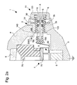
- FIG. 2a shows a partial sectional view of FIG. of the control member 11 along its axis of actuation designated X-X.
- the control members 12, 13, 14 and 15 have a similar configuration.
- the control member 11 is movably mounted in an orifice of assembly 3a formed in the caseband 3 so as to have a translational stroke along the axis of actuation X-X.
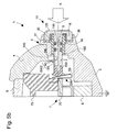
- the control member 11 can be actuated by pressure, like a conventional pusher, to be brought from a position called no depressed, as illustrated in FIG. 2a, at a so-called depressed position, illustrated in Figure 2b.
- the control member 11 consists mainly of a rod 100, elongated form, made of an electrically conductive material, advantageously made of metal.
- This rod 100 preferably, but not exclusively, has a shape cylindrical and crosses the middle part 3 from one side to the other. A first end of the stem 100 thus opens into the cavity formed by the middle part 3 while the second end of the rod 100 opens out of the middle part 3 so as to It can be operated by a user. Watertightness is assured conventional by one or more O-rings 9 housed in one or more grooves 110 formed on the rod 100.
- the rod 100 can be made in one piece.
- This rod could however be made of two parts, one of ordinary conductive material (for example a ordinary stainless steel, e.g. 4C27A) and the other, integral with the former, in one corrosion-resistant material (eg high-performance stainless steel of the type of 316L steel). It would indeed be advantageous to make the exposed portion of the rod 100 in the latter material to prevent corrosion due to sweat or friction, the rest of the rod can be made of a conductive material ordinary.
- the rod 100 On its second end, the rod 100 is terminated by a head 120 more large diameter.
- the rod 100 and the head 120 of the organ of order are made in one piece.
- Overmoulding or mounting a head plastic on the stem should be such that the outer end of the stem can be electrically contacted from the outside.
- the middle part 3 is preferably also made of a material electrically conductive, the rod 100 being consequently isolated from this middle part 3 in an insulating sleeve 30.
- this caseband 3 is elsewhere carried, in operation, at a determined electrical potential, here the potential mass of the portable instrument as schematized in the figures. The utility of this electrical connection will appear more clearly in the rest of this description.
- the caseband 3 could alternatively be made of a non in which case the sleeve 30 is no longer necessary (a conductive element additional power to the determined electrical potential then being required as it is see below).
- the insulating sleeve 30 has a generally tubular shape with a shoulder 31 arranged to bear, from outside the middle part 3, on a corresponding shoulder 3b formed in the mounting hole 3a.
- This sleeve insulation 30 is thus introduced into the mounting hole 3a from the outside and is preferably secured to the middle part 3, for example by driving, screwing or bonding.
- This sleeve 30 may advantageously be made of anodized aluminum, in plastic material, ceramic material or any other material to the extent that minus the contact surface between the sleeve 30 and the conductive parts surrounding is electrically isolated.
- this means of reminder 6 is compressed between the shoulder 31 and the head 120 as illustrated in FIG. FIG. 2b, exerting in this way a restoring force tending to bring back the control from its depressed position to its non-depressed position.
- the shoulder 31 of the insulating sleeve also ensures that the head 120 of the body of control, here conductive, does not come into contact with the caseband 3.
- the control member further comprises a retaining element 40 adapted for axially retaining the rod 100 of the control member.
- the element of retainer 40 is made integral with the rod 100 and is placed on the inner side of the 3 in order to counteract the action of the return means 6 which tends to extract the control member of its housing.
- the retainer 40 is advantageously configured as a traditional retaining key that is introduced into a groove 140 formed on the rod 100.
- This retaining element 40 is also made of an electrically conductive material.
- FIG. 2a it can be seen that, in the non-depressed position, the element of retainer 40 is supported on the middle part 3, at the periphery of the mounting hole 3a.
- an electrical connection is provided, in an unpressed position, between the rod 100 of the control member and the middle part 3.
- the rod 100 of the control member is thus brought to the same electrical potential as the middle part 3.
- this electrical connection is interrupted because of the axial displacement of the retaining element 40 which accompanies the movement of the rod 100.
- the middle part 3 could be made of a material non-conductive, for example plastic, the insulating sleeve 30 no longer necessary.
- a conductive reference element carried at said determined electrical potential and provide that the rod 100 is brought into contact with this reference element position not depressed.
- FIG. 4 shows a variant embodiment where the middle part 3 is not made of an electrically conductive material, making use of the insulation sleeve 30 unnecessary, and where such a reference element 35, for example a metal ring fixed inside the middle part 3, is interposed between the element of 40 and the middle part 3.
- This reference element 35 could for example part of the bezel 4, the latter then being made of a material electrically conductive.
- setting the electrical potential determined from the rod 100 is advantageously and preferably provided by the retention element 40.
- a blade of contact for setting to the determined electrical potential could for example be arranged to cooperate with the rod 100 so that electrical contact with the rod 100 is set in the non-depressed position and interrupted in the depressed analogy to the contact blade with the reference numeral 60 in FIGS. 2a and 2b and whose utility is explained below).
- the structure of the control is such that, in an unpressed position, the rod 100 of the control is brought to a determined electrical potential, thus making it impossible the accumulation of electrical charges on this same rod. In depressed position, by against, this electrical connection is interrupted, making possible the transmission of electrical signals via the rod 100.
- FIG. 3 shows a basic view of the configuration and operation of the control device envisaged to enable the control member to fulfill, in addition to its traditional control function, an additional function allowing the transmission of electrical signals from and / or to the electronic instrument.
- the control member is shown diagrammatically in this figure and bears the reference C.
- This control member C conventionally cooperates with a first electrical contact SW1 to fulfill its control function.
- a control signal SEL is thus produced in response to the activation of the electrical contact SW1, namely in response to a pressure on the control member C.
- a second electrical contact SW2, distinct from the first contact SW1 provides the connection with a I / O input / output line connected for example to a processing unit housed inside the portable electronic instrument.
- This second electrical contact SW2 performs an additional function making it possible to establish an electrical connection between the I / O input / output and the control member C, or more exactly the rod of this control member C.
- This possibility is schematized in FIG. Figure 3 by the connection of the control member C and the input / output I / O through the electrical contact SW2. This connection is established only when the control member C is brought into the depressed position to close the electrical contact SW2. In the non-depressed position, the electrical contact SW2 connects, as shown schematically, the control member C to a determined electrical potential V REF represented here as an electric potential forming a mass.
- V REF an electric potential forming a mass.
- the particularity of the proposed control device lies essentially in that, in the non-depressed position, the electrically conductive portion of the control member C, which serves as electrical connection means with the input / output I / O (ie the rod of the control member), is not left in the floating state but is brought to a specific electrical potential, thus avoiding any accumulation electrical charges on this part of the control member.
- the middle part 3 defines an interior cavity in which place, in a conventional manner, an electronic module 7 (shown partially in FIG. 2a) comprising in particular a printed circuit board, or PCB, 70 carrying various electrical and electronic components (not shown) of which one data processing unit (eg microcontroller or microprocessor), storage means (eg EEPROM, FLASH or the like) and other components for the implementation of the functions of the wristwatch 1.
- watch components time base, frequency divider, display means analog and / or digital, etc.
- Reference 75 indicates an optional spacer element disposed on the upper face of the PCB 70 and which supports in particular the display means of the electronic instrument.
- a source is still partially represented of electrical energy 8 to supply in particular the electronic module 7 above. It can be a traditional battery or an accumulator rechargeable battery (and whose recharge can for example be operated via at least one of the control devices, as already mentioned).
- the first electrical contact SW1 of FIG. is conventionally produced in the form of an electrical contact blade 50 comprising a base secured to the electronic module 7 (this base is here maintained between the PCB 70 and the spacer 75) and a flexible extension that cooperates with the end of the rod 100, this end being electrically isolated from the blade of contact 50 by an insulating sheath 150 that can be made of a material similar to that of the insulating sleeve 30.
- the flexible extension of the contact blade 50 is arranged to be conventionally brought into contact with the other part of the first electrical contact (not shown in Figures 2a and 2b). In this case, it is a metallization 52 formed on the edge of the PCB 70 as illustrated in FIG. partial plan view of Figure 2c.
- Figure 2d shows a plan view similar to that of FIG. 2c, control member 11 depressed position, where we can see the flexible extension of the contact blade 50 coming in contact with metallization 52.
- the insulating sheath 150 fills two functions, namely the electrical insulation between the rod 100 and the first contact electric (whatever the position of the control device) as well as the insulation between the rod 100 and the electrical contact blade 60 (in the non depressed only).
- the electrical contact blade 60 could of course cooperate with an insulating sheath separate from the insulating sheath 150.
- the insulating gain 150 is ended here by a portion larger diameter. This feature is not necessary but allows avoid any possible electrical contact between the blades 50 and 60, the portion of more large diameter being interposed between these two blades.
- the contact blade electrical 60 could be replaced by a cooperating contact blade not directly with the rod 100 but with the retaining element 40. It would be suitable for example of having such a contact blade facing the retaining element of so that an electrical connection with the rod 100 is established, via the retaining element 40, when the control member is brought into its position pressed. Such a variant is illustrated in FIGS. 5a and 5b where one can see that the contact blade 60 previously used is replaced by another blade contact 65 disposed opposite the retaining element 40.
Landscapes
- Physics & Mathematics (AREA)
- General Physics & Mathematics (AREA)
- Electric Clocks (AREA)
- Push-Button Switches (AREA)
- Electromechanical Clocks (AREA)
- Selective Calling Equipment (AREA)
- Lock And Its Accessories (AREA)
- Details Of Measuring Devices (AREA)
- Measuring Pulse, Heart Rate, Blood Pressure Or Blood Flow (AREA)
- Switches With Compound Operations (AREA)
Abstract
Description
- la figure 1 montre une vue en plan générale d'un instrument électronique selon l'invention se présentant ici avantageusement sous la forme d'une montre-bracelet comprenant une pluralité d'organes de commande de type bouton-poussoir ;
- la figure 2a est une vue en coupe de l'un des organes de commande de l'instrument de la figure 1 selon un premier mode de réalisation, cet organe de commande étant illustré dans sa position non enfoncée ;
- la figure 2b est une vue en coupe similaire à celle de la figure 2a où l'organe de commande est illustré en position enfoncée ;
- la figure 2c est une vue en plan partielle de l'organe de commande de la figure 2a dans sa position non enfoncée ;
- la figure 2d est une vue en plan similaire à celle de la figure 2c où l'organe de commande est illustré en position enfoncée ;
- la figure 3 est une vue de principe de la configuration et du fonctionnement de l'organe de commande des figures 2a à 2d où cet organe de commande remplit, outre sa fonction traditionnelle de commande, une fonction additionnelle permettant la transmission de signaux électriques de et/ou vers l'instrument électronique ;
- la figure 4 est une vue en coupe similaire à celle de la figure 3a présentant une variante de réalisation ; et
- les figures 5a et 5b sont des vue en coupes similaires à celles des figures 2a et 2b, respectivement, présentant encore une autre variante de réalisation.
Claims (12)
- Instrument électronique portable (1) comprenant un boítier (2) et une interface utilisateur (11 à 15) pour la sélection de fonctions dudit instrument électronique portable, cette interface utilisateur comprenant au moins un premier organe de commande (11) monté mobile dans un orifice de montage (3a) ménagé dans ledit boítier de façon à avoir une course de translation selon un axe d'actionnement (X-X), cet organe de commande (11) étant actionnable par pression pour être amené d'une position dite non enfoncée à une position dite enfoncée et produire en réponse un signal de commande (SEL),
ledit organe de commande (11) comprenant une tige (100) électriquement conductrice qui traverse ledit orifice de montage et qui comporte des première et seconde extrémités débouchant respectivement à l'intérieur et à l'extérieur dudit boítier (2), cette tige (100) étant adaptée pour permettre la transmission de signaux électriques de et/ou vers l'instrument électronique portable lorsque ledit organe de commande (11) est amené dans ladite position enfoncée,
cet instrument électronique étant caractérisé en ce qu'il comporte en outre des moyens (3, 30, 40; 35, 40) pour amener la tige (100) de l'organe de commande (11) à un potentiel électrique déterminé lorsque ledit organe de commande (11) occupe ladite position non enfoncée et pour interrompre la connexion de la tige (100) de l'organe de commande (11) au dit potentiel électrique déterminé lorsque ledit organe de commande (11) occupe ladite position enfoncée et permettre ainsi la transmission desdits signaux électriques de et/ou vers l'instrument électronique portable. - Instrument électronique portable selon la revendication 1, caractérisé en ce que ledit organe de commande (11) est retenu axialement dans ledit boítier (2) par un élément de retenue (40) solidaire de ladite tige (100) et réalisé en un matériau électriquement conducteur, cet élément de retenue (40) étant amené, lorsque ledit organe de commande (11) occupe ladite position non enfoncée, au contact d'un élément de référence (3; 35) électriquement conducteur qui est porté au dit potentiel électrique déterminé, le contact dudit élément de retenue (40) avec ledit élément de référence (3; 35) étant interrompu lorsque ledit organe de commande (11) est amené en position enfoncée.
- Instrument électronique portable selon la revendication 2, caractérisé en ce que ledit boítier (2) comporte une partie (3) au moins réalisée en un matériau électriquement conducteur et dans laquelle est monté ledit organe de commande (11), cette partie (3) formant ledit élément de référence porté au dit potentiel électrique déterminé, la tige (100) dudit organe de commande étant isolée électriquement de ladite partie électriquement conductrice (3) du boítier (2) par un manchon isolant (30) introduit dans ledit orifice de montage (3a) de l'organe de commande.
- Instrument électronique portable selon la revendication 3, caractérisé en ce que ledit élément de retenue (40) est disposé sur ladite tige (100) à l'intérieur dudit boítier (2), en ce que ledit manchon isolant (30) comporte un épaulement (31) venant en appui avec un épaulement correspondant (3b) ménagé sur ledit orifice de montage (3a) à l'extérieure dudit boítier (2), et en ce que ledit organe de commande (11) comporte en outre une tête (120) solidaire de la seconde extrémité de la tige (100) et présentant un diamètre supérieur au diamètre de la tige (100), un moyen de rappel élastique (6) étant disposé entre ledit épaulement (31) du manchon isolant (30) et ladite tête (120) de l'organe de commande (11) afin de ramener ledit organe de commande (11) de sa position enfoncée à sa position non enfoncée après actionnement.
- Instrument électronique portable selon la revendication 3 ou 4, caractérisé en ce que ledit manchon isolant (30) est réalisé en aluminium éloxé, en matière plastique, en matière céramique, ou toute autre matière comprenant une surface externe électriquement isolante.
- Instrument électronique portable selon l'une quelconque des revendications 2 à 5, caractérisé en ce que ledit élément de retenue (40) est configuré comme une clavette de retenue de poussoir.
- Instrument électronique portable selon l'une quelconque des revendications précédentes, caractérisé en ce que ledit organe de commande (11) coopère avec un premier contact électrique (SW1, 50, 52) actionné par la première extrémité de la tige (100) pour produire ledit signal de commande (SEL), cette première extrémité de la tige (100) étant isolée électriquement par une gaine isolante (150) pour éviter tout contact électrique direct avec ledit premier contact électrique (SW1, 50, 52),
et en ce que ledit organe de commande (11) coopère en outre avec une lame de contact électrique (60; 65) distincte dudit premier contact électrique (SW1, 50, 52), cette lame de contact électrique (60; 65) étant isolée électriquement de ladite tige (100) en position non enfoncée et connectée électriquement à ladite tige (100) en position enfoncée pour permettre ladite transmission de signaux électriques de et/ou vers l'instrument électronique (1). - Instrument électronique portable selon la revendication 7, caractérisé en ce que ladite lame de contact électrique (60) est disposée tangentiellement à ladite tige (100) au voisinage de ladite première extrémité de la tige (100) de sorte que, en position non enfoncée, la lame de contact électrique (60) est en contact avec ladite gaine isolante (150) et de sorte que, en position enfoncée, la lame de contact électrique (60) est en contact avec ladite tige (100).
- Instrument électronique portable selon la revendication 7 en dépendance des revendications 2 à 6, caractérisé en ce que ladite lame de contact électrique (65) n'est pas disposée en contact direct avec la tige (100) dudit organe de commande, cette lame de contact électrique (65) étant disposée en regard dudit élément de retenue (40) de sorte qu'une connexion électrique avec la tige (100) est établie, par l'intermédiaire dudit élément de retenue (40), lorsque ledit organe de commande (11) est amené dans ladite position enfoncée.
- Instrument électronique portable selon l'une quelconque des revendications 7 à 9, caractérisé en ce que ladite gaine isolante (150) est réalisé en aluminium éloxé, en matière plastique, en matière céramique, ou toute autre matière comprenant une surface externe électriquement isolante.
- Instrument électronique portable selon l'une quelconque des revendications précédentes, caractérisé en ce que ladite interface comporte en outre des deuxième (13), troisième (14) et quatrième (15) organes de commande configurés de manière similaire au dit premier organe de commande (11), lesdits premier et deuxième organes de commande (11, 13) étant exploités pour échanger des données avec ledit instrument électronique, lesdits troisième et quatrième organes de commande (14, 15) étant exploités pour assurer la recharge d'un accumulateur (8) dudit instrument électronique.
- Dispositif de commande pour instrument électronique portable, comprenant au moins un organe de commande (11) monté mobile dans un support (3) de façon à avoir une course de translation selon un axe d'actionnement (X-X), cet organe de commande (11) étant actionnable par pression pour être amené d'une position dite non enfoncée à une position dite enfoncée,
ledit organe de commande (11) comprenant une tige (100) électriquement conductrice agencée pour permettre la transmission de signaux électriques de et/ou vers l'instrument électronique portable lorsque ledit organe de commande (11) est amené dans ladite position enfoncée,
ce dispositif de commande comprenant un premier contact électrique (SW1), isolé électriquement de ladite tige (100), et susceptible d'être actionné par l'organe de commande (11) pour produire en réponse un signal de commande (SEL),
ce dispositif de commande comprenant en outre un second contact électrique (SW2) susceptible d'être actionné par l'organe de commande (11) pour établir, en position enfoncée, une liaison électrique entre ladite tige (100) et une ligne d'entrée/sortie (I/O) de l'instrument électronique portable formant une ligne de transmission desdits signaux électriques,
ce dispositif de commande étant caractérisé en ce que, en position non enfoncée, ledit second contact électrique (SW2) établit une liaison électrique entre ladite tige (100) et un potentiel électrique déterminé évitant ainsi l'accumulation de charges électriques sur ladite tige (100).
Priority Applications (10)
| Application Number | Priority Date | Filing Date | Title |
|---|---|---|---|
| DE60306381T DE60306381T2 (de) | 2003-09-23 | 2003-09-23 | Tragbares elektronisches Gerät mit zumindest einem angepassten Betätigungselement zum Übertragen von elektrischen Signalen |
| AT03021443T ATE331323T1 (de) | 2003-09-23 | 2003-09-23 | Tragbares elektronisches gerät mit zumindest einem angepassten betätigungselement zum übertragen von elektrischen signalen |
| EP03021443A EP1519452B1 (fr) | 2003-09-23 | 2003-09-23 | Instrument électronique portable comprenant au moins un organe de commande adapté en outre pour la transmission de signaux électriques |
| TW093128440A TWI392980B (zh) | 2003-09-23 | 2004-09-20 | 包含至少一被設置用以亦傳輸電信號之控制構件的可攜式電子儀器 |
| SG200405586A SG110179A1 (en) | 2003-09-23 | 2004-09-20 | Portable electronic instrument including at least one control member arranged for also transmitting electric signals |
| US10/945,134 US7034237B2 (en) | 2003-09-23 | 2004-09-20 | Portable electronic instrument including at least one control member arranged for also transmitting electric signals |
| KR1020040076296A KR101176643B1 (ko) | 2003-09-23 | 2004-09-23 | 전기 신호를 또한 전송하기 위해 배열된 하나 이상의 제어 부재를 포함하는 휴대용 전기 장치 |
| CNB2004100798499A CN100480903C (zh) | 2003-09-23 | 2004-09-23 | 包括可传输电信号的控制件的便携式电子仪器 |
| JP2004276756A JP4624751B2 (ja) | 2003-09-23 | 2004-09-24 | 電気信号を伝送するために配置された少なくとも1つの制御部材を含む携帯用電子計器 |
| HK05107485.2A HK1075302B (en) | 2003-09-23 | 2005-08-25 | Portable electronic instrument including control member arranged for transmitting electric signals |
Applications Claiming Priority (1)
| Application Number | Priority Date | Filing Date | Title |
|---|---|---|---|
| EP03021443A EP1519452B1 (fr) | 2003-09-23 | 2003-09-23 | Instrument électronique portable comprenant au moins un organe de commande adapté en outre pour la transmission de signaux électriques |
Publications (2)
| Publication Number | Publication Date |
|---|---|
| EP1519452A1 true EP1519452A1 (fr) | 2005-03-30 |
| EP1519452B1 EP1519452B1 (fr) | 2006-06-21 |
Family
ID=34178477
Family Applications (1)
| Application Number | Title | Priority Date | Filing Date |
|---|---|---|---|
| EP03021443A Expired - Lifetime EP1519452B1 (fr) | 2003-09-23 | 2003-09-23 | Instrument électronique portable comprenant au moins un organe de commande adapté en outre pour la transmission de signaux électriques |
Country Status (9)
| Country | Link |
|---|---|
| US (1) | US7034237B2 (fr) |
| EP (1) | EP1519452B1 (fr) |
| JP (1) | JP4624751B2 (fr) |
| KR (1) | KR101176643B1 (fr) |
| CN (1) | CN100480903C (fr) |
| AT (1) | ATE331323T1 (fr) |
| DE (1) | DE60306381T2 (fr) |
| SG (1) | SG110179A1 (fr) |
| TW (1) | TWI392980B (fr) |
Cited By (26)
| Publication number | Priority date | Publication date | Assignee | Title |
|---|---|---|---|---|
| EP1729312A3 (fr) * | 2005-06-02 | 2009-03-04 | Polar Electro Oy | Mécanisme de transmission de puissance |
| FR2972843A1 (fr) * | 2011-03-17 | 2012-09-21 | Ge Energy Products France Snc | Dispositif interrupteur de commande d'un equipement auxiliaire d'une machine |
| US10664074B2 (en) | 2017-06-19 | 2020-05-26 | Apple Inc. | Contact-sensitive crown for an electronic watch |
| US10732571B2 (en) | 2013-08-09 | 2020-08-04 | Apple Inc. | Tactile switch for an electronic device |
| US10845764B2 (en) | 2015-03-08 | 2020-11-24 | Apple Inc. | Compressible seal for rotatable and translatable input mechanisms |
| US10884549B2 (en) | 2014-02-12 | 2021-01-05 | Apple Inc. | Rejection of false turns of rotary inputs for electronic devices |
| US10942491B2 (en) | 2014-09-02 | 2021-03-09 | Apple Inc. | Wearable electronic device |
| US10948880B2 (en) | 2016-07-25 | 2021-03-16 | Apple Inc. | Force-detecting input structure |
| US10955937B2 (en) | 2016-07-15 | 2021-03-23 | Apple Inc. | Capacitive gap sensor ring for an input device |
| US10962935B1 (en) | 2017-07-18 | 2021-03-30 | Apple Inc. | Tri-axis force sensor |
| US11002572B2 (en) | 2015-03-05 | 2021-05-11 | Apple Inc. | Optical encoder with direction-dependent optical properties comprising a spindle having an array of surface features defining a concave contour along a first direction and a convex contour along a second direction |
| US11015960B2 (en) | 2014-07-16 | 2021-05-25 | Apple Inc. | Optical encoder for detecting crown movement |
| US11181863B2 (en) | 2018-08-24 | 2021-11-23 | Apple Inc. | Conductive cap for watch crown |
| US11194299B1 (en) | 2019-02-12 | 2021-12-07 | Apple Inc. | Variable frictional feedback device for a digital crown of an electronic watch |
| US11194298B2 (en) | 2018-08-30 | 2021-12-07 | Apple Inc. | Crown assembly for an electronic watch |
| US11360440B2 (en) | 2018-06-25 | 2022-06-14 | Apple Inc. | Crown for an electronic watch |
| US11531306B2 (en) | 2013-06-11 | 2022-12-20 | Apple Inc. | Rotary input mechanism for an electronic device |
| US11550268B2 (en) | 2020-06-02 | 2023-01-10 | Apple Inc. | Switch module for electronic crown assembly |
| US11561515B2 (en) | 2018-08-02 | 2023-01-24 | Apple Inc. | Crown for an electronic watch |
| US11796961B2 (en) | 2018-08-24 | 2023-10-24 | Apple Inc. | Conductive cap for watch crown |
| US11796968B2 (en) | 2018-08-30 | 2023-10-24 | Apple Inc. | Crown assembly for an electronic watch |
| US12092996B2 (en) | 2021-07-16 | 2024-09-17 | Apple Inc. | Laser-based rotation sensor for a crown of an electronic watch |
| US12104929B2 (en) | 2016-05-17 | 2024-10-01 | Apple Inc. | Rotatable crown for an electronic device |
| US12189347B2 (en) | 2022-06-14 | 2025-01-07 | Apple Inc. | Rotation sensor for a crown of an electronic watch |
| US12259690B2 (en) | 2018-08-24 | 2025-03-25 | Apple Inc. | Watch crown having a conductive surface |
| US12596334B2 (en) | 2023-02-07 | 2026-04-07 | Apple Inc. | Crown for an electronic watch |
Families Citing this family (17)
| Publication number | Priority date | Publication date | Assignee | Title |
|---|---|---|---|---|
| JP4407657B2 (ja) * | 2006-03-15 | 2010-02-03 | セイコーエプソン株式会社 | 時計のボタン構造およびこれを備えた時計 |
| FR2913524B1 (fr) * | 2007-03-05 | 2009-04-17 | Itt Mfg Enterprises Inc | Commutateur electrique a effort de rappel variable. |
| EP2107432B1 (fr) * | 2008-04-01 | 2011-06-29 | Montres Rado S.A. | Dispositif de commande à poussoir pour montre |
| US7822469B2 (en) * | 2008-06-13 | 2010-10-26 | Salutron, Inc. | Electrostatic discharge protection for analog component of wrist-worn device |
| EP4513293A3 (fr) * | 2013-06-11 | 2025-06-04 | Apple Inc. | Montre électronique à mécanisme d'entrée rotatif |
| US10394325B2 (en) | 2013-12-10 | 2019-08-27 | Apple Inc. | Input friction mechanism for rotary inputs of electronic devices |
| US9651405B1 (en) | 2015-03-06 | 2017-05-16 | Apple Inc. | Dynamic adjustment of a sampling rate for an optical encoder |
| CN106159617A (zh) * | 2015-03-26 | 2016-11-23 | 群光电子股份有限公司 | 电子装置、和具有电子装置及船坞座的结构 |
| US10018966B2 (en) | 2015-04-24 | 2018-07-10 | Apple Inc. | Cover member for an input mechanism of an electronic device |
| US10503271B2 (en) | 2015-09-30 | 2019-12-10 | Apple Inc. | Proximity detection for an input mechanism of an electronic device |
| EP3185079B1 (fr) * | 2015-12-21 | 2019-08-21 | ETA SA Manufacture Horlogère Suisse | Dispositif de bouton-poussoir pour une montre-bracelet électronique ou électromécanique |
| CN105543930A (zh) * | 2015-12-22 | 2016-05-04 | 安徽华东光电技术研究所 | 铝制绝缘套管及其制备方法 |
| JP6588832B2 (ja) * | 2016-01-14 | 2019-10-09 | 東京パーツ工業株式会社 | ドアハンドル装置 |
| US9891651B2 (en) | 2016-02-27 | 2018-02-13 | Apple Inc. | Rotatable input mechanism having adjustable output |
| US10866619B1 (en) | 2017-06-19 | 2020-12-15 | Apple Inc. | Electronic device having sealed button biometric sensing system |
| US10203662B1 (en) | 2017-09-25 | 2019-02-12 | Apple Inc. | Optical position sensor for a crown |
| US10300545B2 (en) | 2017-10-12 | 2019-05-28 | Snap Inc. | Low-profile mechanical retention |
Citations (3)
| Publication number | Priority date | Publication date | Assignee | Title |
|---|---|---|---|---|
| EP1109084A1 (fr) * | 1999-12-15 | 2001-06-20 | Eta SA Fabriques d'Ebauches | Moyens pour recharger l'accumulateur d'une montre |
| EP1134630A1 (fr) * | 2000-03-17 | 2001-09-19 | Eta SA Fabriques d'Ebauches | Moyens pour charger ou extraire des informations d'un objet portatif tel que, notamment, une pièce d'horlogerie |
| EP1168113A1 (fr) * | 2000-06-20 | 2002-01-02 | The Swatch Group Management Services AG | Dispositif de commutation électrique entre au moins trois contacts différents |
Family Cites Families (12)
| Publication number | Priority date | Publication date | Assignee | Title |
|---|---|---|---|---|
| US4170104A (en) * | 1976-12-01 | 1979-10-09 | Citizen Watch Company Limited | Switch mechanism for wristwatch |
| JPH038794U (fr) * | 1989-06-15 | 1991-01-28 | ||
| SG93287A1 (en) * | 1999-12-15 | 2002-12-17 | Ebauchesfabrik Eta Ag | Means for recharging a watch accumulator |
| SG106600A1 (en) * | 2000-03-17 | 2004-10-29 | Ebauchesfabrik Eta Ag | Means for loading or extracting data from a portable object, such as, in particular, a timepiece |
| SG109448A1 (en) * | 2000-05-11 | 2005-03-30 | Swatch Group Man Serv Ag | Portable electronic device such as, in particular, a timepiece, fitted with a push-button |
| SG100707A1 (en) * | 2000-06-07 | 2003-12-26 | Ebauchesfabrik Eta Ag | Control device with a snap function and watch fitted therewith |
| US6483058B2 (en) * | 2000-09-07 | 2002-11-19 | Itt Manufacturing Enterprises, Inc. | Sealed manual reset switch |
| TW494286B (en) * | 2000-09-19 | 2002-07-11 | Ebauchesfabrik Eta Ag | Device for electrically connecting an electrical power source and an electronic circuit of a timepiece |
| JP2002272003A (ja) * | 2001-03-05 | 2002-09-20 | Seiko Epson Corp | 小型情報機器、小型情報機器の充電方法、充電制御プログラムおよび記録媒体 |
| ITMI20012002A1 (it) * | 2001-09-27 | 2003-03-27 | Vimar Spa | Meccanismo di azionamento a compressione mediante tasto basculante diinterruttori commutatori deviatori e simili |
| US6846998B2 (en) * | 2002-01-28 | 2005-01-25 | Citizen Watch Co., Ltd. | Switch connecting structure for timepiece |
| JP4506218B2 (ja) * | 2003-03-31 | 2010-07-21 | セイコーエプソン株式会社 | ボタン構造、およびこれを備えた携帯機器 |
-
2003
- 2003-09-23 EP EP03021443A patent/EP1519452B1/fr not_active Expired - Lifetime
- 2003-09-23 AT AT03021443T patent/ATE331323T1/de not_active IP Right Cessation
- 2003-09-23 DE DE60306381T patent/DE60306381T2/de not_active Expired - Lifetime
-
2004
- 2004-09-20 SG SG200405586A patent/SG110179A1/en unknown
- 2004-09-20 US US10/945,134 patent/US7034237B2/en not_active Expired - Lifetime
- 2004-09-20 TW TW093128440A patent/TWI392980B/zh not_active IP Right Cessation
- 2004-09-23 CN CNB2004100798499A patent/CN100480903C/zh not_active Expired - Fee Related
- 2004-09-23 KR KR1020040076296A patent/KR101176643B1/ko not_active Expired - Fee Related
- 2004-09-24 JP JP2004276756A patent/JP4624751B2/ja not_active Expired - Fee Related
Patent Citations (3)
| Publication number | Priority date | Publication date | Assignee | Title |
|---|---|---|---|---|
| EP1109084A1 (fr) * | 1999-12-15 | 2001-06-20 | Eta SA Fabriques d'Ebauches | Moyens pour recharger l'accumulateur d'une montre |
| EP1134630A1 (fr) * | 2000-03-17 | 2001-09-19 | Eta SA Fabriques d'Ebauches | Moyens pour charger ou extraire des informations d'un objet portatif tel que, notamment, une pièce d'horlogerie |
| EP1168113A1 (fr) * | 2000-06-20 | 2002-01-02 | The Swatch Group Management Services AG | Dispositif de commutation électrique entre au moins trois contacts différents |
Cited By (54)
| Publication number | Priority date | Publication date | Assignee | Title |
|---|---|---|---|---|
| EP1729312A3 (fr) * | 2005-06-02 | 2009-03-04 | Polar Electro Oy | Mécanisme de transmission de puissance |
| FR2972843A1 (fr) * | 2011-03-17 | 2012-09-21 | Ge Energy Products France Snc | Dispositif interrupteur de commande d'un equipement auxiliaire d'une machine |
| US11531306B2 (en) | 2013-06-11 | 2022-12-20 | Apple Inc. | Rotary input mechanism for an electronic device |
| US10732571B2 (en) | 2013-08-09 | 2020-08-04 | Apple Inc. | Tactile switch for an electronic device |
| US10962930B2 (en) | 2013-08-09 | 2021-03-30 | Apple Inc. | Tactile switch for an electronic device |
| US11886149B2 (en) | 2013-08-09 | 2024-01-30 | Apple Inc. | Tactile switch for an electronic device |
| US12181840B2 (en) | 2013-08-09 | 2024-12-31 | Apple Inc. | Tactile switch for an electronic device |
| US11669205B2 (en) | 2014-02-12 | 2023-06-06 | Apple Inc. | Rejection of false turns of rotary inputs for electronic devices |
| US10884549B2 (en) | 2014-02-12 | 2021-01-05 | Apple Inc. | Rejection of false turns of rotary inputs for electronic devices |
| US12307047B2 (en) | 2014-02-12 | 2025-05-20 | Apple Inc. | Rejection of false turns of rotary inputs for electronic devices |
| US12045416B2 (en) | 2014-02-12 | 2024-07-23 | Apple Inc. | Rejection of false turns of rotary inputs for electronic devices |
| US11347351B2 (en) | 2014-02-12 | 2022-05-31 | Apple Inc. | Rejection of false turns of rotary inputs for electronic devices |
| US11015960B2 (en) | 2014-07-16 | 2021-05-25 | Apple Inc. | Optical encoder for detecting crown movement |
| US11221590B2 (en) | 2014-09-02 | 2022-01-11 | Apple Inc. | Wearable electronic device |
| US10942491B2 (en) | 2014-09-02 | 2021-03-09 | Apple Inc. | Wearable electronic device |
| US11762342B2 (en) | 2014-09-02 | 2023-09-19 | Apple Inc. | Wearable electronic device |
| US11474483B2 (en) | 2014-09-02 | 2022-10-18 | Apple Inc. | Wearable electronic device |
| US11002572B2 (en) | 2015-03-05 | 2021-05-11 | Apple Inc. | Optical encoder with direction-dependent optical properties comprising a spindle having an array of surface features defining a concave contour along a first direction and a convex contour along a second direction |
| US11988995B2 (en) | 2015-03-08 | 2024-05-21 | Apple Inc. | Compressible seal for rotatable and translatable input mechanisms |
| US10845764B2 (en) | 2015-03-08 | 2020-11-24 | Apple Inc. | Compressible seal for rotatable and translatable input mechanisms |
| US12104929B2 (en) | 2016-05-17 | 2024-10-01 | Apple Inc. | Rotatable crown for an electronic device |
| US10955937B2 (en) | 2016-07-15 | 2021-03-23 | Apple Inc. | Capacitive gap sensor ring for an input device |
| US11513613B2 (en) | 2016-07-15 | 2022-11-29 | Apple Inc. | Capacitive gap sensor ring for an input device |
| US12086331B2 (en) | 2016-07-15 | 2024-09-10 | Apple Inc. | Capacitive gap sensor ring for an input device |
| US10948880B2 (en) | 2016-07-25 | 2021-03-16 | Apple Inc. | Force-detecting input structure |
| US12105479B2 (en) | 2016-07-25 | 2024-10-01 | Apple Inc. | Force-detecting input structure |
| US11720064B2 (en) | 2016-07-25 | 2023-08-08 | Apple Inc. | Force-detecting input structure |
| US12619201B2 (en) | 2016-07-25 | 2026-05-05 | Apple Inc. | Force-detecting input structure |
| US11385599B2 (en) | 2016-07-25 | 2022-07-12 | Apple Inc. | Force-detecting input structure |
| US10664074B2 (en) | 2017-06-19 | 2020-05-26 | Apple Inc. | Contact-sensitive crown for an electronic watch |
| US12066795B2 (en) | 2017-07-18 | 2024-08-20 | Apple Inc. | Tri-axis force sensor |
| US10962935B1 (en) | 2017-07-18 | 2021-03-30 | Apple Inc. | Tri-axis force sensor |
| US12105480B2 (en) | 2018-06-25 | 2024-10-01 | Apple Inc. | Crown for an electronic watch |
| US11754981B2 (en) | 2018-06-25 | 2023-09-12 | Apple Inc. | Crown for an electronic watch |
| US11360440B2 (en) | 2018-06-25 | 2022-06-14 | Apple Inc. | Crown for an electronic watch |
| US12282302B2 (en) | 2018-08-02 | 2025-04-22 | Apple Inc. | Crown for an electronic watch |
| US11561515B2 (en) | 2018-08-02 | 2023-01-24 | Apple Inc. | Crown for an electronic watch |
| US11906937B2 (en) | 2018-08-02 | 2024-02-20 | Apple Inc. | Crown for an electronic watch |
| US12259690B2 (en) | 2018-08-24 | 2025-03-25 | Apple Inc. | Watch crown having a conductive surface |
| US11796961B2 (en) | 2018-08-24 | 2023-10-24 | Apple Inc. | Conductive cap for watch crown |
| US11181863B2 (en) | 2018-08-24 | 2021-11-23 | Apple Inc. | Conductive cap for watch crown |
| US12276943B2 (en) | 2018-08-24 | 2025-04-15 | Apple Inc. | Conductive cap for watch crown |
| US12326697B2 (en) | 2018-08-30 | 2025-06-10 | Apple Inc. | Crown assembly for an electronic watch |
| US11796968B2 (en) | 2018-08-30 | 2023-10-24 | Apple Inc. | Crown assembly for an electronic watch |
| US11194298B2 (en) | 2018-08-30 | 2021-12-07 | Apple Inc. | Crown assembly for an electronic watch |
| US11860587B2 (en) | 2019-02-12 | 2024-01-02 | Apple Inc. | Variable frictional feedback device for a digital crown of an electronic watch |
| US11194299B1 (en) | 2019-02-12 | 2021-12-07 | Apple Inc. | Variable frictional feedback device for a digital crown of an electronic watch |
| US12346070B2 (en) | 2019-02-12 | 2025-07-01 | Apple Inc. | Variable frictional feedback device for a digital crown of an electronic watch |
| US12189342B2 (en) | 2020-06-02 | 2025-01-07 | Apple Inc. | Switch module for electronic crown assembly |
| US11550268B2 (en) | 2020-06-02 | 2023-01-10 | Apple Inc. | Switch module for electronic crown assembly |
| US11815860B2 (en) | 2020-06-02 | 2023-11-14 | Apple Inc. | Switch module for electronic crown assembly |
| US12092996B2 (en) | 2021-07-16 | 2024-09-17 | Apple Inc. | Laser-based rotation sensor for a crown of an electronic watch |
| US12189347B2 (en) | 2022-06-14 | 2025-01-07 | Apple Inc. | Rotation sensor for a crown of an electronic watch |
| US12596334B2 (en) | 2023-02-07 | 2026-04-07 | Apple Inc. | Crown for an electronic watch |
Also Published As
| Publication number | Publication date |
|---|---|
| US7034237B2 (en) | 2006-04-25 |
| TWI392980B (zh) | 2013-04-11 |
| KR20050030143A (ko) | 2005-03-29 |
| HK1075302A1 (zh) | 2005-12-09 |
| US20050061646A1 (en) | 2005-03-24 |
| KR101176643B1 (ko) | 2012-08-28 |
| ATE331323T1 (de) | 2006-07-15 |
| EP1519452B1 (fr) | 2006-06-21 |
| TW200519555A (en) | 2005-06-16 |
| CN1601408A (zh) | 2005-03-30 |
| JP2005099023A (ja) | 2005-04-14 |
| CN100480903C (zh) | 2009-04-22 |
| JP4624751B2 (ja) | 2011-02-02 |
| DE60306381T2 (de) | 2007-06-14 |
| SG110179A1 (en) | 2005-04-28 |
| DE60306381D1 (de) | 2006-08-03 |
Similar Documents
| Publication | Publication Date | Title |
|---|---|---|
| EP1519452B1 (fr) | Instrument électronique portable comprenant au moins un organe de commande adapté en outre pour la transmission de signaux électriques | |
| EP2607972B1 (fr) | Poussoir étanche pour montre | |
| EP1519453B1 (fr) | Instrument électronique portable comprenant au moins un terminal d'entrée et/ou sortie adapté pour établir une communication avec une unité électronique logée à l'intérieur dudit instrument | |
| EP4134005B1 (fr) | Montre connectée avec lunette rotative | |
| WO2003005486A1 (fr) | Antenne pour montre bracelet | |
| EP1519457B1 (fr) | Adaptateur pour instrument électronique portable et système de transmission entre ces deux éléments | |
| EP1489471A1 (fr) | Connexion de masse d'une plaquette de circuit imprimé dans un instrument électronique du type montre-bracelet | |
| CH705043A2 (fr) | Pièce d'horlogerie portable incluant un bouton-poussoir. | |
| EP0603721B1 (fr) | Pièce d'horlogerie comportant une antenne d'émission d'un signal électromagnétique | |
| WO2022112962A1 (fr) | Fond intelligent pour boîtiers de montre-bracelet | |
| EP1134630B1 (fr) | Moyens pour charger ou extraire des informations d'un objet portatif tel que, notamment, une pièce d'horlogerie | |
| EP3362858B1 (fr) | Bracelet de montre | |
| EP3483661B1 (fr) | Ensemble comprenant un objet portable de petites dimensions et un outil d'actionnement d'un bouton poussoir correcteur équipant ledit objet portable de petites dimensions tel qu'une pièce d'horlogerie | |
| EP1730605B1 (fr) | Dispositif correcteur pour piece d'horlogerie | |
| EP0446770A1 (fr) | Réveil | |
| EP1109084B1 (fr) | Moyens pour recharger l'accumulateur d'une montre | |
| CH705933A2 (fr) | Poussoir étanche pour montre. | |
| FR2613849A1 (fr) | Dispositif de mesure du temps | |
| EP0452254A1 (fr) | Dispositif de commande de fonctions par le fond du boîtier d'une montre | |
| FR2898976A1 (fr) | Structure de thermometre electronique. | |
| WO2026098968A1 (fr) | Chargeur pour dispositif portable avec couronne | |
| WO2004114341A2 (fr) | Interrupteur de dispositif electronique et dispositif electronique avertisseur muni d’un tel interrupteur | |
| FR2701616A1 (fr) | Système électronique de transmission à radiofréquence. | |
| EP4390575A1 (fr) | Système de réglage d'une fonction d'illumination d'une montre | |
| CH357344A (fr) | Montre lumineuse |
Legal Events
| Date | Code | Title | Description |
|---|---|---|---|
| PUAI | Public reference made under article 153(3) epc to a published international application that has entered the european phase |
Free format text: ORIGINAL CODE: 0009012 |
|
| AK | Designated contracting states |
Kind code of ref document: A1 Designated state(s): AT BE BG CH CY CZ DE DK EE ES FI FR GB GR HU IE IT LI LU MC NL PT RO SE SI SK TR |
|
| AX | Request for extension of the european patent |
Extension state: AL LT LV MK |
|
| 17P | Request for examination filed |
Effective date: 20050930 |
|
| GRAP | Despatch of communication of intention to grant a patent |
Free format text: ORIGINAL CODE: EPIDOSNIGR1 |
|
| AKX | Designation fees paid |
Designated state(s): AT BE BG CH CY CZ DE DK EE ES FI FR GB GR HU IE IT LI LU MC NL PT RO SE SI SK TR |
|
| GRAS | Grant fee paid |
Free format text: ORIGINAL CODE: EPIDOSNIGR3 |
|
| GRAA | (expected) grant |
Free format text: ORIGINAL CODE: 0009210 |
|
| AK | Designated contracting states |
Kind code of ref document: B1 Designated state(s): AT BE BG CH CY CZ DE DK EE ES FI FR GB GR HU IE IT LI LU MC NL PT RO SE SI SK TR |
|
| PG25 | Lapsed in a contracting state [announced via postgrant information from national office to epo] |
Ref country code: AT Free format text: LAPSE BECAUSE OF FAILURE TO SUBMIT A TRANSLATION OF THE DESCRIPTION OR TO PAY THE FEE WITHIN THE PRESCRIBED TIME-LIMIT Effective date: 20060621 Ref country code: SK Free format text: LAPSE BECAUSE OF FAILURE TO SUBMIT A TRANSLATION OF THE DESCRIPTION OR TO PAY THE FEE WITHIN THE PRESCRIBED TIME-LIMIT Effective date: 20060621 Ref country code: NL Free format text: LAPSE BECAUSE OF FAILURE TO SUBMIT A TRANSLATION OF THE DESCRIPTION OR TO PAY THE FEE WITHIN THE PRESCRIBED TIME-LIMIT Effective date: 20060621 Ref country code: IE Free format text: LAPSE BECAUSE OF FAILURE TO SUBMIT A TRANSLATION OF THE DESCRIPTION OR TO PAY THE FEE WITHIN THE PRESCRIBED TIME-LIMIT Effective date: 20060621 Ref country code: CZ Free format text: LAPSE BECAUSE OF FAILURE TO SUBMIT A TRANSLATION OF THE DESCRIPTION OR TO PAY THE FEE WITHIN THE PRESCRIBED TIME-LIMIT Effective date: 20060621 Ref country code: IT Free format text: LAPSE BECAUSE OF FAILURE TO SUBMIT A TRANSLATION OF THE DESCRIPTION OR TO PAY THE FEE WITHIN THE PRESCRIBED TIME-LIMIT;WARNING: LAPSES OF ITALIAN PATENTS WITH EFFECTIVE DATE BEFORE 2007 MAY HAVE OCCURRED AT ANY TIME BEFORE 2007. THE CORRECT EFFECTIVE DATE MAY BE DIFFERENT FROM THE ONE RECORDED. Effective date: 20060621 Ref country code: SI Free format text: LAPSE BECAUSE OF FAILURE TO SUBMIT A TRANSLATION OF THE DESCRIPTION OR TO PAY THE FEE WITHIN THE PRESCRIBED TIME-LIMIT Effective date: 20060621 Ref country code: RO Free format text: LAPSE BECAUSE OF FAILURE TO SUBMIT A TRANSLATION OF THE DESCRIPTION OR TO PAY THE FEE WITHIN THE PRESCRIBED TIME-LIMIT Effective date: 20060621 Ref country code: FI Free format text: LAPSE BECAUSE OF FAILURE TO SUBMIT A TRANSLATION OF THE DESCRIPTION OR TO PAY THE FEE WITHIN THE PRESCRIBED TIME-LIMIT Effective date: 20060621 |
|
| REG | Reference to a national code |
Ref country code: GB Ref legal event code: FG4D Free format text: NOT ENGLISH |
|
| REG | Reference to a national code |
Ref country code: CH Ref legal event code: EP |
|
| REG | Reference to a national code |
Ref country code: IE Ref legal event code: FG4D Free format text: LANGUAGE OF EP DOCUMENT: FRENCH |
|
| REF | Corresponds to: |
Ref document number: 60306381 Country of ref document: DE Date of ref document: 20060803 Kind code of ref document: P |
|
| PG25 | Lapsed in a contracting state [announced via postgrant information from national office to epo] |
Ref country code: SE Free format text: LAPSE BECAUSE OF FAILURE TO SUBMIT A TRANSLATION OF THE DESCRIPTION OR TO PAY THE FEE WITHIN THE PRESCRIBED TIME-LIMIT Effective date: 20060921 Ref country code: DK Free format text: LAPSE BECAUSE OF FAILURE TO SUBMIT A TRANSLATION OF THE DESCRIPTION OR TO PAY THE FEE WITHIN THE PRESCRIBED TIME-LIMIT Effective date: 20060921 |
|
| PG25 | Lapsed in a contracting state [announced via postgrant information from national office to epo] |
Ref country code: MC Free format text: LAPSE BECAUSE OF NON-PAYMENT OF DUE FEES Effective date: 20060930 Ref country code: BE Free format text: LAPSE BECAUSE OF NON-PAYMENT OF DUE FEES Effective date: 20060930 |
|
| PG25 | Lapsed in a contracting state [announced via postgrant information from national office to epo] |
Ref country code: ES Free format text: LAPSE BECAUSE OF FAILURE TO SUBMIT A TRANSLATION OF THE DESCRIPTION OR TO PAY THE FEE WITHIN THE PRESCRIBED TIME-LIMIT Effective date: 20061002 |
|
| REG | Reference to a national code |
Ref country code: CH Ref legal event code: NV Representative=s name: ICB INGENIEURS CONSEILS EN BREVETS SA |
|
| GBT | Gb: translation of ep patent filed (gb section 77(6)(a)/1977) |
Effective date: 20060924 |
|
| PG25 | Lapsed in a contracting state [announced via postgrant information from national office to epo] |
Ref country code: PT Free format text: LAPSE BECAUSE OF FAILURE TO SUBMIT A TRANSLATION OF THE DESCRIPTION OR TO PAY THE FEE WITHIN THE PRESCRIBED TIME-LIMIT Effective date: 20061121 |
|
| NLV1 | Nl: lapsed or annulled due to failure to fulfill the requirements of art. 29p and 29m of the patents act | ||
| REG | Reference to a national code |
Ref country code: IE Ref legal event code: FD4D |
|
| PLBE | No opposition filed within time limit |
Free format text: ORIGINAL CODE: 0009261 |
|
| STAA | Information on the status of an ep patent application or granted ep patent |
Free format text: STATUS: NO OPPOSITION FILED WITHIN TIME LIMIT |
|
| 26N | No opposition filed |
Effective date: 20070322 |
|
| BERE | Be: lapsed |
Owner name: ASULAB S.A. Effective date: 20060930 |
|
| PG25 | Lapsed in a contracting state [announced via postgrant information from national office to epo] |
Ref country code: GR Free format text: LAPSE BECAUSE OF FAILURE TO SUBMIT A TRANSLATION OF THE DESCRIPTION OR TO PAY THE FEE WITHIN THE PRESCRIBED TIME-LIMIT Effective date: 20060922 |
|
| PG25 | Lapsed in a contracting state [announced via postgrant information from national office to epo] |
Ref country code: BG Free format text: LAPSE BECAUSE OF FAILURE TO SUBMIT A TRANSLATION OF THE DESCRIPTION OR TO PAY THE FEE WITHIN THE PRESCRIBED TIME-LIMIT Effective date: 20060921 Ref country code: EE Free format text: LAPSE BECAUSE OF FAILURE TO SUBMIT A TRANSLATION OF THE DESCRIPTION OR TO PAY THE FEE WITHIN THE PRESCRIBED TIME-LIMIT Effective date: 20060621 |
|
| PG25 | Lapsed in a contracting state [announced via postgrant information from national office to epo] |
Ref country code: TR Free format text: LAPSE BECAUSE OF FAILURE TO SUBMIT A TRANSLATION OF THE DESCRIPTION OR TO PAY THE FEE WITHIN THE PRESCRIBED TIME-LIMIT Effective date: 20060621 Ref country code: LU Free format text: LAPSE BECAUSE OF NON-PAYMENT OF DUE FEES Effective date: 20060923 Ref country code: HU Free format text: LAPSE BECAUSE OF FAILURE TO SUBMIT A TRANSLATION OF THE DESCRIPTION OR TO PAY THE FEE WITHIN THE PRESCRIBED TIME-LIMIT Effective date: 20061222 |
|
| PG25 | Lapsed in a contracting state [announced via postgrant information from national office to epo] |
Ref country code: CY Free format text: LAPSE BECAUSE OF FAILURE TO SUBMIT A TRANSLATION OF THE DESCRIPTION OR TO PAY THE FEE WITHIN THE PRESCRIBED TIME-LIMIT Effective date: 20060621 |
|
| PGFP | Annual fee paid to national office [announced via postgrant information from national office to epo] |
Ref country code: GB Payment date: 20130823 Year of fee payment: 11 |
|
| GBPC | Gb: european patent ceased through non-payment of renewal fee |
Effective date: 20140923 |
|
| PG25 | Lapsed in a contracting state [announced via postgrant information from national office to epo] |
Ref country code: GB Free format text: LAPSE BECAUSE OF NON-PAYMENT OF DUE FEES Effective date: 20140923 |
|
| REG | Reference to a national code |
Ref country code: FR Ref legal event code: PLFP Year of fee payment: 13 |
|
| REG | Reference to a national code |
Ref country code: FR Ref legal event code: PLFP Year of fee payment: 14 |
|
| REG | Reference to a national code |
Ref country code: FR Ref legal event code: PLFP Year of fee payment: 15 |
|
| REG | Reference to a national code |
Ref country code: CH Ref legal event code: PFUS Owner name: THE SWATCH GROUP RESEARCH AND DEVELOPMENT LTD , CH Free format text: FORMER OWNER: ASULAB S.A., CH |
|
| REG | Reference to a national code |
Ref country code: FR Ref legal event code: PLFP Year of fee payment: 16 |
|
| PGFP | Annual fee paid to national office [announced via postgrant information from national office to epo] |
Ref country code: FR Payment date: 20190820 Year of fee payment: 17 Ref country code: DE Payment date: 20190820 Year of fee payment: 17 |
|
| REG | Reference to a national code |
Ref country code: DE Ref legal event code: R119 Ref document number: 60306381 Country of ref document: DE |
|
| PG25 | Lapsed in a contracting state [announced via postgrant information from national office to epo] |
Ref country code: FR Free format text: LAPSE BECAUSE OF NON-PAYMENT OF DUE FEES Effective date: 20200930 Ref country code: DE Free format text: LAPSE BECAUSE OF NON-PAYMENT OF DUE FEES Effective date: 20210401 |
|
| PGFP | Annual fee paid to national office [announced via postgrant information from national office to epo] |
Ref country code: CH Payment date: 20221001 Year of fee payment: 20 |
|
| P01 | Opt-out of the competence of the unified patent court (upc) registered |
Effective date: 20230814 |
|
| REG | Reference to a national code |
Ref country code: CH Ref legal event code: PL |