EP1519470A2 - Machine à bobiner à axe horizontal - Google Patents
Machine à bobiner à axe horizontal Download PDFInfo
- Publication number
- EP1519470A2 EP1519470A2 EP04255740A EP04255740A EP1519470A2 EP 1519470 A2 EP1519470 A2 EP 1519470A2 EP 04255740 A EP04255740 A EP 04255740A EP 04255740 A EP04255740 A EP 04255740A EP 1519470 A2 EP1519470 A2 EP 1519470A2
- Authority
- EP
- European Patent Office
- Prior art keywords
- wire
- stator
- winding tool
- winding
- nest
- Prior art date
- Legal status (The legal status is an assumption and is not a legal conclusion. Google has not performed a legal analysis and makes no representation as to the accuracy of the status listed.)
- Withdrawn
Links
- 238000004804 winding Methods 0.000 title claims abstract description 130
- 230000008878 coupling Effects 0.000 description 5
- 238000010168 coupling process Methods 0.000 description 5
- 238000005859 coupling reaction Methods 0.000 description 5
- 238000010276 construction Methods 0.000 description 3
- 238000000034 method Methods 0.000 description 3
- 229910000831 Steel Inorganic materials 0.000 description 2
- 230000007246 mechanism Effects 0.000 description 2
- 230000008569 process Effects 0.000 description 2
- 230000009467 reduction Effects 0.000 description 2
- 239000010959 steel Substances 0.000 description 2
- 230000005540 biological transmission Effects 0.000 description 1
- 230000001419 dependent effect Effects 0.000 description 1
- 230000005484 gravity Effects 0.000 description 1
- 230000010355 oscillation Effects 0.000 description 1
- 230000001360 synchronised effect Effects 0.000 description 1
Images


Classifications
-
- H—ELECTRICITY
- H02—GENERATION; CONVERSION OR DISTRIBUTION OF ELECTRIC POWER
- H02K—DYNAMO-ELECTRIC MACHINES
- H02K15/00—Processes or apparatus specially adapted for manufacturing, assembling, maintaining or repairing of dynamo-electric machines
- H02K15/08—Forming windings by laying conductors into or around core parts
- H02K15/085—Forming windings by laying conductors into or around core parts by laying conductors into slotted stators
-
- Y—GENERAL TAGGING OF NEW TECHNOLOGICAL DEVELOPMENTS; GENERAL TAGGING OF CROSS-SECTIONAL TECHNOLOGIES SPANNING OVER SEVERAL SECTIONS OF THE IPC; TECHNICAL SUBJECTS COVERED BY FORMER USPC CROSS-REFERENCE ART COLLECTIONS [XRACs] AND DIGESTS
- Y10—TECHNICAL SUBJECTS COVERED BY FORMER USPC
- Y10T—TECHNICAL SUBJECTS COVERED BY FORMER US CLASSIFICATION
- Y10T29/00—Metal working
- Y10T29/49—Method of mechanical manufacture
- Y10T29/49002—Electrical device making
- Y10T29/49009—Dynamoelectric machine
Definitions
- the present invention relates generally to stator winding and, more particularly, to an apparatus and method for winding coils on stators for dynamo-electric machines, including an improved winding apparatus for providing improved winding speeds.
- Field winding coils for stators are generally placed on the radially inwardly extending teeth of a stator by either preforming the coils and then pressing the preformed coils over the stator teeth, or by winding the coils directly onto the stator teeth.
- the coils are pushed onto the stator by a coil pusher which forcibly pushes the coils over the teeth of the stator, and a forming tool, or forming tools, may be provided to shape the wire in the stator slots and around the ends of the teeth in order to compactly position the coils on the stator.
- the winding tool includes a plurality of forming racks which are adapted to move radially outwardly from the winding tool in order to press the end portions of the coil windings radially outwardly and thereby facilitate placement of additional wire within the slots of the stator.
- a further winding tool for forming coils directly onto a stator is disclosed in U.S. Patent No. 6,616,082 which describes a vertical winding machine including a winding tool which moves in reciprocating movement through the stator as wire is fed onto the stator teeth. During movement of the winding tool, a drifting tool is moved into engagement with the wire coils being formed such that a drifting operation is performed simultaneously with movement of the winding tool to place wire around the stator teeth.
- an apparatus for winding the stator for a dynamoelectric machine comprising: a stator nest located on a support base for holding a stator, the stator nest defining a horizontal longitudinal axis and including a front side for receiving a stator and an opposite back side; a winding tool extending through the stator nest from the back side toward the front side, the winding tool comprising a hollow tubular member for guiding wire to a stator located in the stator nest; a reciprocating driver connected to the winding tool for driving the winding tool in reciprocating movement relative to the stator nest; an oscillating driver connected to the winding tool for driving the winding tool in oscillating movement; and a wire feeder for feeding wire through the winding tool, the wire feeder supported for reciprocating movement with the winding tool.
- an apparatus for winding the stator for a dynamoelectric machine comprising: a stator nest located on a support base for holding a stator, the stator nest defining a longitudinal axis and including a front side for receiving a stator and an opposite back side; a winding tool extending through the stator nest from the back side toward the front side, the winding tool comprising a hollow tubular member for guiding wire to a stator located in the stator nest; a reciprocating driver connected to the winding tool for driving the winding tool in reciprocating movement relative to the stator nest; an oscillating driver including a drive motor connected to the winding tool for driving the winding tool in oscillating movement; and a wire feeder connected for feeding wire through the winding tool, the wire feeder supported for reciprocating movement with the winding tool, and the wire feeder including a wire outlet substantially aligned with the longitudinal axis of the stator nest.
- a wire feeder for an apparatus for winding the stator of a dynamoelectric machine
- the wire feeder comprising: a wire drive roller; at least one pressing roller cooperating engagement with the wire drive roller; a wire entry for receiving a wire and directing it toward the drive roller; a wire exit for receiving the wire from the drive roller; and a wire guide having a surface conformed to an outer surface of the drive roller for guiding the wire in a path encircling the outer surface of the drive roller.
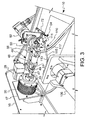
- the present invention provides a horizontal winding apparatus for winding stators for dynamoelectric machines.
- the apparatus comprises a support base 10 mounting a generally cylindrical stator nest 12 defining a horizontally extending longitudinal axis 14.
- the stator nest 12 is supported to the support base 10 by a vertical mounting plate 16.
- the stator nest 12 comprises a collet 18 sized to receive a stator for engagement with a cylindrical exterior surface of the stator.
- an actuator 20 for the collet 18 is provided mounted to a collet mount 17 for actuating the collet 18 between a closed and an open position for engaging and disengaging with a stator located within the collet 18.
- the actuator 20 preferably comprises an air actuated collet closer, such as an air collet closer manufactured by Dunham Tool Company of New Fairfield, Connecticut.
- the collet 18 is supported for rotation about the longitudinal axis 14 and includes an exterior toothed member defining a collet gear 22.
- a toothed drive belt 24 extends around the collet gear 22 and passes around a drive sprocket 26 which is supported on the vertical mounting plate 16.
- the drive sprocket 26 is driven by a servo motor 28 (Fig. 3), defining a nest driver, to cause the collet 18 to be driven in rotational movement to position the stator nest 12 at precise rotational positions, as specified by a programmable controller (not shown).
- the stator nest 12 may be rotated to a different rotational position prior to each coil winding operation performed by a winding tool 32.
- One or more belt tensioning members 30 are provided along the top and bottom runs of the drive belt 24 to stabilize and maintain tension on the drive belt 24.
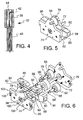
- the winding tool 32 (Fig. 4) extends through the stator nest 12 in a direction from a back side toward a front side 34 of the stator nest 12.
- the winding tool 32 includes a winding head 38 sized to fit relatively closely within the interior diameter of a stator 118 supported within the stator nest 12, and a rigid winding tool shaft 40 attached to one end of the winding head 38.
- the winding head 38 and winding tool shaft 40 are both formed as hollow members for permitting passage of winding wire therethrough, and the winding head 38 defines at least one wire feed opening 42 extending radially through its side wall for passage of wire from the winding head 38 to a stator 118 held in the stator nest 12.
- Wire is guided through the winding tool 32 to the wire feed opening 42 by a flexible guide tube 44, such as a plastic tube, extending though the winding tool shaft 40 and winding head 38.
- a flexible guide tube 44 such as a plastic tube, extending though the winding tool shaft 40 and winding head 38. It should be understood that although only one wire feed opening 42 and guide tube 44 are shown, a plurality of wire feed openings and guide tubes may be provided, one for each wire to be fed by the winding tool 32 during a stator winding operation.
- the winding tool 32 extends rearwardly from the stator nest 12 and extends through a support tube 45.
- the support tube 45 is connected to a clamp plate 47 which is attached to a reciprocating structure 46 comprising a reciprocating arm 48 having one end attached to an eccentric drive member 50 driven by a servo motor 52 supported on the base support 10.
- a coupling housing 49 is attached to the clamp plate 47, for reciprocating movement with the clamp plate 47, and further supports an oscillating drive motor 56.
- a torque transmitting coupling 51 within the coupling housing 49 transfers rotational movement from the drive motor 56 to the winding tool shaft 40 to provide controlled rotation of the winding head 38.
- the winding tool shaft 40 is supported within the support tube 45 for reciprocating movement with the reciprocating arm 48 and support tube 45, and is further supported for rotating or oscillating movement to provide reciprocating and oscillating movement to the winding head 38.
- a wire feeder 54 is supported at an end of the drive motor 56 opposite from the coupling housing 49 for pushing wire W through the winding tool 32 and out of the wire feed opening 42.
- the wire feeder 54 reciprocates with the drive motor 56 and the coupling housing 49, such that the wire feeder 54 is located in substantially fixed relationship to the winding tool 32.
- the oscillating drive motor 56 comprises a servo motor defining a rotational axis which substantially coincides with the longitudinal axis 14, and which is connected to the winding tool shaft 40 to actuate the winding tool shaft 40 in controlled rotation during a winding operation.
- the winding tool shaft 40 may be rotated to form end turns of wire at the opposing ends of the stator teeth, and further may be rotated to facilitate placement of wire within skewed slots where it is necessary to both rotate and move the winding tool 32 longitudinally as the wire is fed into the stator slots.
- the oscillating drive motor 56 is positioned such that it provides a direct rotational drive to the winding tool 32, without intermediate connecting structure, such as gears or belts, to transmit the rotational movement of the servo motor, resulting in a reduction in weight and corresponding reduction in inertia of the oscillating members associated with the winding tool 32.
- the wire feeder 54 comprises a steel drive roller 58 and a set of three pressure rollers 60, 62, 64 in cooperating engagement with the drive roller 58.
- the pressure rollers 60, 62, 64 comprise idler rollers supported on respective idler shafts 66, 68, 70 and each of the pressure rollers 60, 62, 64 include a resilient outer surface, such as a rubber surface, for contacting the steel circumferential surface of the drive roller 58.
- the drive roller 58 is supported on a drive shaft 72 for driving the roller 58 in rotation.
- the idler shafts 66, 68, 70 and drive shaft 72 are supported between two side plates 74, 76 defining opposing sides of the wire feeder 54.
- a wire entry guide 78 is located between the side plates 74, 76 on an entry side of the wire feeder 54 and a wire exit guide 80 is located on an exit side of the wire feeder 54.
- the wire entry guide 78 includes an upper surface 82 defining a wire guide groove 84, and an entry cover plate 86 positioned over the upper surface 82 to cooperate with the groove 84 in defining a passage for wire to pass into the wire feeder 54 toward the drive roller 58.
- the wire exit guide 80 includes an upper surface 88 defining a wire guide groove 90, and an exit cover plate 92 positioned over the upper surface 88 to cooperate with the groove in defining a passage for wire to pass from the drive roller 58 and out of the wire feeder 54 through an exit opening 94.
- the wire passes out of the exit opening 94 and into the guide tube 44, passing through the center of the drive motor 56 and into the winding tool shaft 40 for guiding wire to the wire feed opening 42 of the winding tool 32.
- a lower wire guide 96 is also provided, located below the drive roller 58, and includes a curved surface 98 conformed to the outer surface of the drive roller 58 and defining a wire guide groove 100 for guiding and maintaining the position of wire passing around the drive roller 58.
- the wire entry guide 78 and wire exit guide 80 each include respective curved surfaces 102, 104.
- the surface 102 defines a wire guide groove 106 and the surface 104 similarly includes a wire guide groove (not shown) for guiding and maintaining the position of wire passing around the drive roller 58.
- the drive roller 58 is driven in rotation by sensing servo motor 108 which is mounted to the base support 10, and which is connected to the wire feeder drive shaft 72 by an angle drive connection 110.
- the sensing servo motor 108 uses sensed conditions related to operation of the motor 108 to consistently maintain operation of the motor 108 at a desired speed.
- the angle drive connection 110 is illustrated as comprising a pair of universal joints 111, 113, a shaft portion 115 and a sliding spline shaft connection 117 along the shaft portion 115 to accommodate reciprocating movement of the wire feeder 54 relative to the servo motor 108.
- the angle drive connection 110 permits the servo motor 108 to be mounted separate from the oscillating parts associated with the wire feed and thereby reduces the amount of weight, and associated inertia, that must be actuated by the servo motor 52 for the reciprocating structure 46. It should be understood that the term "angle drive connection" is intended to encompass any drive structure which permits transmission of rotational power from the motor 108 to the wire feeder 54 along a path which is not a direct line between the rotational axis of the motor 108 and the rotational axis of the drive shaft 72 of the wire feeder 54, including flexible drive shafts and similar structures.
- a drift tool structure 112 including a drift tool head 114 located adjacent the front side 34 of the stator nest 12.
- the drift tool head 114 comprises a plurality of radially extending drift tool blades 116.
- the drift tool head 114 is actuated by a linear servo motor 119 for reciprocating movement toward and away from a stator 118 positioned within the stator nest 12 to move the blades 116 into the slots of the stator 118 for engaging and forming wire wound around the stator teeth 120.
- the drift tool head 114 may be moved into and out of engagement with the stator 118 in synchronous movement with the winding tool 32, or may be moved into engagement with the stator 118 intermittently at predetermined intervals in the winding operation.
- the structure and operation of the drift tool 112 may be similar to the operation of the drift tool disclosed in U.S. Patent No. 6,616,082, which patent is incorporated herein by reference.
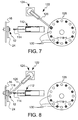
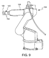
- the transfer structure 122 comprises a robot 124 (see also Fig. 9) having an articulated arm 126 for moving stators 118 from a stator supply or tray 128 to the stator nest 12 in preparation for a winding operation, and for moving the wound stators 118 from the stator nest back to the tray 128.
- the tray 128 preferably comprises a turntable having a plurality of shallow circular slots 130 sized to receive the stators 118, the turntable being actuated for rotation by the controller for the system to bring a particular slot into position for transfer of a stator to or from the robot arm 126.
- the robot 124 preferably comprises a Motoman SV3X robot having a stator pickup member 140 on the end of the arm 126, such as a pickup member 140 having a plurality radially movable jaw members 142 (Fig. 10).
- the pickup member 140 may comprise a pneumatically actuated 3-jaw gripper available from Process Equipment Co., Robotic Accessories Division, of Tipp City, Ohio.
- Each jaw member 142 preferably includes a blade portion 148 for engagement with the inside of the stator 118, the blade portions 148 engaging with the stator slots for maintaining a desired rotational orientation of the stator 118 as it is loaded into the stator nest 12. As seen in Fig.
- the radially movable members 142 are engaged outwardly against the interior of a stator 118.
- a spring biased plate 154 supported on pins 156, is biased back against springs 158 when the stator 118 is in position on the radially movable members 142.
- the spring biased plate 154 acts to push the stator 118 off the pickup member 140 when the radially movable members 142 are retracted inwardly in order to ensure positive transfer of the stator 118 to either the collet 18 or to the tray 128.
- Fig. 6 diagrammatically illustrates the robot arm 126 extended toward the tray 128 to pick up a stator 118 in preparation for transfer to the stator nest 12 prior to a winding operation. It should be noted that every other slot 130 in the tray contains a stator 118, leaving empty slots 130 in between for receiving wound stators 118.
- Figs. 7 diagrammatically illustrates the robot arm 126 transferring a stator 118 to the stator nest 12. Upon completion of a stator winding operation, the robot arm 126 will return to the position illustrated in Fig. 7 to remove the stator 118 from the stator nest 12 and subsequently transfer the wound stator 118 to one of the empty slots 130 in the tray 128.
- provision of the robot 124 to move the stators 118 between a supply and collection tray 128 and the winding machine collet 18 reduces the time required between winding operations. Further, it should be understood that the provision of a winding machine in which horizontal reciprocation of the winding tool 32 is implemented, rather than the vertical movement of prior machines, substantially reduces the inertial forces resulting from moving winding apparatus components against the force of gravity. Also, the inertial forces associated with movement of the winding tool 32 are additionally reduced by positioning the wire feed motor 108 apart from the wire feeder 54 with an angle drive connection, and by providing the oscillating drive motor 56 in line with the winding tool shaft 40.
Landscapes
- Engineering & Computer Science (AREA)
- Manufacturing & Machinery (AREA)
- Power Engineering (AREA)
- Manufacture Of Motors, Generators (AREA)
Applications Claiming Priority (2)
| Application Number | Priority Date | Filing Date | Title |
|---|---|---|---|
| US50514903P | 2003-09-23 | 2003-09-23 | |
| US505149P | 2003-09-23 |
Publications (2)
| Publication Number | Publication Date |
|---|---|
| EP1519470A2 true EP1519470A2 (fr) | 2005-03-30 |
| EP1519470A3 EP1519470A3 (fr) | 2006-02-01 |
Family
ID=34193395
Family Applications (1)
| Application Number | Title | Priority Date | Filing Date |
|---|---|---|---|
| EP04255740A Withdrawn EP1519470A3 (fr) | 2003-09-23 | 2004-09-20 | Machine à bobiner à axe horizontal |
Country Status (2)
| Country | Link |
|---|---|
| US (2) | US7028942B2 (fr) |
| EP (1) | EP1519470A3 (fr) |
Cited By (2)
| Publication number | Priority date | Publication date | Assignee | Title |
|---|---|---|---|---|
| CN103066775A (zh) * | 2012-12-28 | 2013-04-24 | 深圳市方能达科技有限公司 | 电动车定子绕线机 |
| CN103475172A (zh) * | 2013-09-24 | 2013-12-25 | 浙江省三门县王中王电机焊接设备有限公司 | 飞盘式全自动绕线机及其绕线方法 |
Families Citing this family (7)
| Publication number | Priority date | Publication date | Assignee | Title |
|---|---|---|---|---|
| CN104578619B (zh) * | 2014-12-31 | 2016-02-10 | 佛山市吉星家电有限公司 | 定子绕线机 |
| US10910901B2 (en) | 2015-11-05 | 2021-02-02 | Globe Motors, Inc. | Wound stator with insulation system forming a wire guide for a winding operation |
| US9991050B2 (en) * | 2016-03-08 | 2018-06-05 | Ming-Chang Lee | Wire winding device for stator |
| CN110224558B (zh) * | 2019-04-29 | 2024-03-19 | 苏州恊合自动化科技有限公司 | 一种飞叉绕线机构 |
| US12316176B2 (en) * | 2021-11-17 | 2025-05-27 | Baker Hughes Oilfield Operations Llc | Method for external winding of ESP motor using a split core stator |
| US12463510B2 (en) | 2022-03-30 | 2025-11-04 | Persimmon Technologies Corporation | Needle winding for high density copper fill internal tooth electric motor stator and method therefor |
| CN218988428U (zh) * | 2022-10-12 | 2023-05-09 | 浙江铜加工研究院有限公司 | 自动化收卷机构及多工位收卷装置 |
Family Cites Families (18)
| Publication number | Priority date | Publication date | Assignee | Title |
|---|---|---|---|---|
| US3082966A (en) | 1958-01-15 | 1963-03-26 | Link Engineering Company | Coil winding machine |
| CH430857A (de) | 1965-08-11 | 1967-02-28 | Fort Wayne Tool & Die Inc | Statorwickelmaschine |
| US4498636A (en) | 1982-02-25 | 1985-02-12 | Kollmorgen Technologies Corporation | Stator winding apparatus and method |
| AU572468B2 (en) * | 1982-08-23 | 1988-05-12 | F F Seeley Nominees Pty Ltd | Connection guide for electric motor |
| JPS61111279A (ja) | 1984-11-01 | 1986-05-29 | Kamei Mach Project Kk | 巻線機ノズルの揺動方式 |
| US4616788A (en) * | 1985-02-05 | 1986-10-14 | The Globe Tool & Engineering Co. | Method and apparatus for winding dynamoelectric devices |
| GB8626731D0 (en) * | 1986-11-08 | 1986-12-10 | Apsley Metals Ltd | Cord guide device |
| US4791271A (en) * | 1987-04-06 | 1988-12-13 | Crc-Evans Pipeline International, Inc. | Capstan drive assembly for filler wire in electric arc welding |
| US5860615A (en) * | 1995-10-30 | 1999-01-19 | Labinal Components And Systems, Inc. | Tool including winding spindle for winding and forming dynamoelectric machine field windings |
| US5845863A (en) * | 1995-11-06 | 1998-12-08 | Sony Corporation | Winding apparatus for simultaneous winding of two CRT yokes |
| WO1998011653A1 (fr) | 1996-09-10 | 1998-03-19 | Labinal Components & Systems, Inc. | Procede et appareil permettant d'enrouler et de former des bobines de champ pour des machines dynamo-electriques |
| IT1306121B1 (it) | 1998-05-05 | 2001-05-29 | Raffaella Fedi | Sistema asservito programmabile, che consente l'integrazione framoto lineare alternato e moto circolare alternato, per la formazione |
| US6286815B1 (en) * | 1998-05-15 | 2001-09-11 | Brian N. Ray | Wire puller |
| JP3451033B2 (ja) * | 1999-04-28 | 2003-09-29 | 日特エンジニアリング株式会社 | 巻線装置 |
| US6533208B1 (en) * | 1999-08-12 | 2003-03-18 | Axis U.S.A., Inc. | Winding cores with stratification motion |
| US6732971B2 (en) * | 2000-07-13 | 2004-05-11 | Axis U.S.A., Inc. | Apparatus and methods for winding and transferring dynamoelectric machine stators |
| US6616082B2 (en) | 2000-10-16 | 2003-09-09 | Globe Motors, Inc. | Machine for winding dynamo-electric stators |
| JP3647374B2 (ja) * | 2001-01-09 | 2005-05-11 | 日特エンジニアリング株式会社 | 巻線装置および巻線方法 |
-
2004
- 2004-09-16 US US10/942,509 patent/US7028942B2/en not_active Expired - Fee Related
- 2004-09-20 EP EP04255740A patent/EP1519470A3/fr not_active Withdrawn
-
2006
- 2006-02-06 US US11/347,948 patent/US7191974B2/en not_active Expired - Lifetime
Cited By (3)
| Publication number | Priority date | Publication date | Assignee | Title |
|---|---|---|---|---|
| CN103066775A (zh) * | 2012-12-28 | 2013-04-24 | 深圳市方能达科技有限公司 | 电动车定子绕线机 |
| CN103066775B (zh) * | 2012-12-28 | 2015-03-04 | 深圳市方能达科技有限公司 | 电动车定子绕线机 |
| CN103475172A (zh) * | 2013-09-24 | 2013-12-25 | 浙江省三门县王中王电机焊接设备有限公司 | 飞盘式全自动绕线机及其绕线方法 |
Also Published As
| Publication number | Publication date |
|---|---|
| US7028942B2 (en) | 2006-04-18 |
| US20060124798A1 (en) | 2006-06-15 |
| EP1519470A3 (fr) | 2006-02-01 |
| US7191974B2 (en) | 2007-03-20 |
| US20050061906A1 (en) | 2005-03-24 |
Similar Documents
| Publication | Publication Date | Title |
|---|---|---|
| US7028942B2 (en) | Horizontal winding machine | |
| US7325764B2 (en) | Method and apparatus for winding field coils for dynamo-electric machines | |
| JP7044891B2 (ja) | 携帯式ケーブルタイ工具 | |
| CN108666841B (zh) | 全自动线束加工组装设备 | |
| CN110603218A (zh) | 卷绕和切割线或线缆的设备和方法 | |
| CN114362462B (zh) | 用于步进减速电机的多工位自动组装设备 | |
| JPS643043B2 (fr) | ||
| KR101692749B1 (ko) | 테이프의 처짐이 방지될 수 있는 테이프 권취장치 | |
| CN113245663B (zh) | 一种机械零件焊接装置 | |
| US7441456B1 (en) | Drive shaft balancer and method utilizing weight transporting electrodes | |
| CN221164831U (zh) | 一种流转装置及管件套环机 | |
| CN109926820B (zh) | 一种绝缘电缆夹的包胶和组装设备 | |
| CN212783061U (zh) | 一种机芯线圈绕制设备 | |
| US7419116B2 (en) | Method and apparatus for winding field coils for dynamo-electric machines | |
| RU2581875C2 (ru) | Машина для закрывания гибких упаковок | |
| US5582357A (en) | Coil winding apparatus | |
| JP7075333B2 (ja) | コイル成形方法及びコイル成形装置 | |
| CN222281780U (zh) | 双工位绕线机 | |
| CN117997056B (zh) | 一种自动套管分块绕线机 | |
| US6164584A (en) | Winding machine | |
| CN217514674U (zh) | 全自动纸管合盖打钉机 | |
| CN119660043B (zh) | 一种胶带打包捆扎设备 | |
| WO2021199440A1 (fr) | Dispositif de coupe de soudure, unité de coupe de soudure, dispositif de montage de pièce et système de production | |
| CN218538668U (zh) | 一种复卷机抽轴装置 | |
| CN213185822U (zh) | 一种绕线装置及绕线机 |
Legal Events
| Date | Code | Title | Description |
|---|---|---|---|
| PUAI | Public reference made under article 153(3) epc to a published international application that has entered the european phase |
Free format text: ORIGINAL CODE: 0009012 |
|
| AK | Designated contracting states |
Kind code of ref document: A2 Designated state(s): AT BE BG CH CY CZ DE DK EE ES FI FR GB GR HU IE IT LI LU MC NL PL PT RO SE SI SK TR |
|
| AX | Request for extension of the european patent |
Extension state: AL HR LT LV MK |
|
| PUAL | Search report despatched |
Free format text: ORIGINAL CODE: 0009013 |
|
| AK | Designated contracting states |
Kind code of ref document: A3 Designated state(s): AT BE BG CH CY CZ DE DK EE ES FI FR GB GR HU IE IT LI LU MC NL PL PT RO SE SI SK TR |
|
| AX | Request for extension of the european patent |
Extension state: AL HR LT LV MK |
|
| 17P | Request for examination filed |
Effective date: 20060426 |
|
| 17Q | First examination report despatched |
Effective date: 20060717 |
|
| AKX | Designation fees paid |
Designated state(s): DE FR IT PT |
|
| STAA | Information on the status of an ep patent application or granted ep patent |
Free format text: STATUS: THE APPLICATION IS DEEMED TO BE WITHDRAWN |
|
| 18D | Application deemed to be withdrawn |
Effective date: 20080827 |