EP1520061B1 - Procede permettant d'appliquer des alliages anticorrosion sur des tubes metalliques - Google Patents
Procede permettant d'appliquer des alliages anticorrosion sur des tubes metalliques Download PDFInfo
- Publication number
- EP1520061B1 EP1520061B1 EP03763016A EP03763016A EP1520061B1 EP 1520061 B1 EP1520061 B1 EP 1520061B1 EP 03763016 A EP03763016 A EP 03763016A EP 03763016 A EP03763016 A EP 03763016A EP 1520061 B1 EP1520061 B1 EP 1520061B1
- Authority
- EP
- European Patent Office
- Prior art keywords
- tube
- alloy
- casing
- rollers
- interior surface
- Prior art date
- Legal status (The legal status is an assumption and is not a legal conclusion. Google has not performed a legal analysis and makes no representation as to the accuracy of the status listed.)
- Expired - Lifetime
Links
- 239000000956 alloy Substances 0.000 title claims abstract description 79
- 229910045601 alloy Inorganic materials 0.000 title claims abstract description 71
- 238000000034 method Methods 0.000 title claims abstract description 55
- 239000011248 coating agent Substances 0.000 title claims abstract description 25
- 238000000576 coating method Methods 0.000 title claims abstract description 25
- 238000005260 corrosion Methods 0.000 title abstract description 9
- 230000007797 corrosion Effects 0.000 title abstract description 9
- 238000010438 heat treatment Methods 0.000 claims abstract description 33
- 238000009987 spinning Methods 0.000 claims abstract description 15
- 238000001816 cooling Methods 0.000 claims description 15
- 239000002826 coolant Substances 0.000 claims description 12
- 230000007246 mechanism Effects 0.000 claims description 11
- 239000011261 inert gas Substances 0.000 claims description 8
- 230000008018 melting Effects 0.000 claims description 7
- 238000002844 melting Methods 0.000 claims description 7
- 239000000843 powder Substances 0.000 claims description 7
- 238000010791 quenching Methods 0.000 claims description 7
- 239000007789 gas Substances 0.000 claims description 5
- 239000007921 spray Substances 0.000 claims description 5
- OKTJSMMVPCPJKN-UHFFFAOYSA-N Carbon Chemical compound [C] OKTJSMMVPCPJKN-UHFFFAOYSA-N 0.000 claims description 3
- 229910002804 graphite Inorganic materials 0.000 claims description 3
- 239000010439 graphite Substances 0.000 claims description 3
- 230000000171 quenching effect Effects 0.000 claims description 3
- 239000008188 pellet Substances 0.000 claims 2
- 239000007787 solid Substances 0.000 claims 2
- RYGMFSIKBFXOCR-UHFFFAOYSA-N Copper Chemical compound [Cu] RYGMFSIKBFXOCR-UHFFFAOYSA-N 0.000 claims 1
- 229910052802 copper Inorganic materials 0.000 claims 1
- 239000010949 copper Substances 0.000 claims 1
- 238000005299 abrasion Methods 0.000 abstract description 4
- 239000000463 material Substances 0.000 description 9
- 230000006698 induction Effects 0.000 description 6
- 229910000831 Steel Inorganic materials 0.000 description 5
- 239000010959 steel Substances 0.000 description 5
- 229910052751 metal Inorganic materials 0.000 description 4
- 239000002184 metal Substances 0.000 description 4
- 238000005266 casting Methods 0.000 description 3
- 239000012530 fluid Substances 0.000 description 3
- 238000007747 plating Methods 0.000 description 3
- 229910000990 Ni alloy Inorganic materials 0.000 description 2
- QVGXLLKOCUKJST-UHFFFAOYSA-N atomic oxygen Chemical compound [O] QVGXLLKOCUKJST-UHFFFAOYSA-N 0.000 description 2
- 238000010586 diagram Methods 0.000 description 2
- 239000001301 oxygen Substances 0.000 description 2
- 229910052760 oxygen Inorganic materials 0.000 description 2
- 239000000126 substance Substances 0.000 description 2
- XLYOFNOQVPJJNP-UHFFFAOYSA-N water Substances O XLYOFNOQVPJJNP-UHFFFAOYSA-N 0.000 description 2
- VYZAMTAEIAYCRO-UHFFFAOYSA-N Chromium Chemical compound [Cr] VYZAMTAEIAYCRO-UHFFFAOYSA-N 0.000 description 1
- HAONYNZNTBGJHI-UHFFFAOYSA-N [C].[Ni].[W] Chemical compound [C].[Ni].[W] HAONYNZNTBGJHI-UHFFFAOYSA-N 0.000 description 1
- 239000002253 acid Substances 0.000 description 1
- 238000005229 chemical vapour deposition Methods 0.000 description 1
- 239000000788 chromium alloy Substances 0.000 description 1
- 238000010276 construction Methods 0.000 description 1
- 239000006185 dispersion Substances 0.000 description 1
- 238000009826 distribution Methods 0.000 description 1
- -1 e.g. Substances 0.000 description 1
- 230000000694 effects Effects 0.000 description 1
- 230000008020 evaporation Effects 0.000 description 1
- 238000001704 evaporation Methods 0.000 description 1
- 238000007733 ion plating Methods 0.000 description 1
- 239000007788 liquid Substances 0.000 description 1
- 239000000155 melt Substances 0.000 description 1
- 238000012986 modification Methods 0.000 description 1
- 230000004048 modification Effects 0.000 description 1
- 229910000623 nickel–chromium alloy Inorganic materials 0.000 description 1
- 239000003129 oil well Substances 0.000 description 1
- 239000002245 particle Substances 0.000 description 1
- 238000005240 physical vapour deposition Methods 0.000 description 1
- 238000007670 refining Methods 0.000 description 1
- 230000000284 resting effect Effects 0.000 description 1
- 238000004544 sputter deposition Methods 0.000 description 1
Images


Classifications
-
- C—CHEMISTRY; METALLURGY
- C23—COATING METALLIC MATERIAL; COATING MATERIAL WITH METALLIC MATERIAL; CHEMICAL SURFACE TREATMENT; DIFFUSION TREATMENT OF METALLIC MATERIAL; COATING BY VACUUM EVAPORATION, BY SPUTTERING, BY ION IMPLANTATION OR BY CHEMICAL VAPOUR DEPOSITION, IN GENERAL; INHIBITING CORROSION OF METALLIC MATERIAL OR INCRUSTATION IN GENERAL
- C23C—COATING METALLIC MATERIAL; COATING MATERIAL WITH METALLIC MATERIAL; SURFACE TREATMENT OF METALLIC MATERIAL BY DIFFUSION INTO THE SURFACE, BY CHEMICAL CONVERSION OR SUBSTITUTION; COATING BY VACUUM EVAPORATION, BY SPUTTERING, BY ION IMPLANTATION OR BY CHEMICAL VAPOUR DEPOSITION, IN GENERAL
- C23C24/00—Coating starting from inorganic powder
- C23C24/08—Coating starting from inorganic powder by application of heat or pressure and heat
- C23C24/10—Coating starting from inorganic powder by application of heat or pressure and heat with intermediate formation of a liquid phase in the layer
Definitions
- Methods and apparatuses for coating the interior surface of a casing, pipe or tube, with an alloy, such as a corrosion-resistant alloy are disclosed. More specifically, methods and apparatuses are disclosed for metallizing the interior surface of metallic tubular bodies, to provide, for example, metallic casings with interior surfaces, coated with a corrosion-resistant and/or abrasion-resistant alloy coating to extend the useful life of the casings in harsh operating environments.
- metallic casing pipes are used to transport fluids.
- ordinary or low-cost steel is used to fabricate the casing in order to reduce capital costs.
- the interior surface of metal casings are often exposed to corrosive or abrasive environments.
- oil well casings are often exposed to high salinity water or acid, both of which promote corrosion of ordinary steels.
- the fluids transported through the casings may be abrasive or corrosive, or both.
- plating techniques is undesirable because plating, such as chrome plating, requires the use of chemical baths, which are environmentally undesirable and it is also difficult to deposit a plated layer with sufficient thickness to achieve the desired corrosion-resistant and/or abrasion-resistant effects.
- powder coating techniques are useful for coating the exterior surfaces of structures, but no efficient powder coating techniques have been developed for coating the interior surfaces of structures, such as metal casings.
- chemical vapor deposition and physical vapor deposition techniques such as evaporation, ion plating, and sputtering, have not been adequately developed for coating interior surfaces such as the inside of a metal casing.
- the technique disclosed in the '638 patent requires the complex apparatus with a plurality of rollers designed to accommodate the metal casing as it changes in diameter while being heated and requires the casing to be passed through the heating apparatus.
- the costs required to construct the apparatus disclosed in the '638 patent are substantial.
- the technique disclosed in the '453 patent requires the coating materials provided in elongated rods that are placed longitudinally within the casing. Thus, the elongated rods of alloy material must also be specially prepared.
- the induction heating process of the '453 patent also requires a complex apparatus as the casing must be transported through the induction heating mechanism.
- DE-A 10 064 384 discloses a process and apparatus for producing a wear-resistant coating on the cylindrical interior surface of a horizontally disposed metallic tube by placing a strip-shaped material on the surface to be coated, by closing the tube ends with a cap, by induction heating and melting the strip-shaped material while rotating the tube on rollers.
- JP-A-60 255 984 discloses a method for forming a layer on the interior surface of a horizontally disposed tube comprising introducing metallic powders into the tube, heating the tube through spaced conducting rollers and rotating the tube.
- EP-A-1 036 611 discloses a method of forming a wear-resistant lining on an interior surface of a cylinder, placed in a high temperature furnace or induction coil for melting the lining components, such as powders or castings. After melting the cylinder is placed on rollers.
- JP-A-07 140 824 discloses a heating roller constituted of a thin walled pipe provided with a cylindrical layer and heated by supplying current to two longitudinally spaced electrodes connected to the tube.
- US-A-2 880 109 discloses a method of lining the interior of cylinders comprising charging dry divided alloy particles to the cylinder, capping the cylinder ends, mounting the cylinder in a suitable apparatus for rotating and heating the cylinder.
- One disclosed method comprises placing a quantity of an alloy in the tube, enclosing the ends of the tube with caps, at least one of which is vented, heating the tube with resistance heating by applying current across the tube sufficient to heat the tube and melt the alloy, and spinning the tube about a longitudinal axis of the tube to distribute the molten alloy along the interior surface of the tube using centrifugal forces generated by the spinning of the tube.
- One disclosed apparatus comprises a vertically adjustable support for supporting the metallic tube in a horizontal position.
- the apparatus also comprises at least two spaced-apart rollers and up to several sets of rollers in alignment with the vertical support for receiving the tube when the support is lowered to place the tube on the rollers in a horizontal position.
- At least one of the rollers is linked to a drive mechanism for rotating the roller and imparting rotation to the tube.
- the apparatus also includes two electrodes for detachable connection to opposing ends of the tube which are used to heat the tube, with the alloy disposed therein, prior to the placement of the tube on the rollers.
- the apparatus also includes two caps, at least one of which is vented for releasing gases generated during the heating and subsequent spinning of the tube.
- the apparatus may also include a supply of inert gas connected to one of the caps.
- the apparatus may also include a cooling mechanism such as a coolant spray device or a quench tank.
- FIG. 1 An apparatus 10 used to coat an interior surface 11 of a metallic tube 12 is disclosed in Fig. 1.
- the tube 12 is supported on vertically adjustable supports 13, 14 in a horizontal position as shown. Alloy material is placed within the tube 12 and the opposing ends 15, 16 of the tube are covered with caps shown in phantom at 17, 18.
- a positive electrode 21 and a negative electrode 22 are attached or placed into engagement with the tube 12 near the opposing ends 15, 16 thereof.
- the electrodes 21, 22 are connected to a power supply 23. With the alloy material in place along the interior 11 of the tube 12, the tube is heated by applying current across the tube, by way of the electrodes 21, 22 resulting in a resistance heating of the tube 12.
- the apparatus 10 enables the tube 12 to be coated with an alloy material using a resistant heating technique.
- the apparatus 10 may also include a gas supply 32 that is coupled to one of the end caps, e.g., 17, as shown in Fig. 1.
- the gas supply 32 may be an inert gas supply which may improve the structure of the alloy/casing bond along the interior 11 of the tube 12.
- the gas supply 32 may simply be a supply of air used to enhance the cooling of the tube during the spinning of the tube on the rollers 24-27. Further, a separate inert gas supply and oxygen supply may be provided.
- a supply of coolant 33 may be provided and connected to a spray nozzle 34 which sprays coolant, e.g., water or other suitable coolant, to the exterior surface 35 of the tube during the spinning of the tube on the rollers 24-27.
- a quench tank 36 may be provided and the entire tube 12 may be placed in the liquid-filled quench tank after the spinning on the rollers 24-27 and distributing of the alloy about the interior 11 of the tube 12.
- FIG. 2 A flow diagram for the above-described methods is illustrated in Fig. 2.
- Metallic tubing is provided at step 40 and placed on horizontal supports at 41.
- the alloy is then inserted at 42.
- a step 43 may be included which inserts graphite with the alloy.
- the addition of graphite with the alloy would help to remove oxygen from the tube during the melting and casting of the alloy about the interior surface of the tube.
- the electrodes are attached at 44 and the resistance heating is carried out at 45. Again, inert gas may be flowed through the tube at 46 to improve the bonding characteristics.
- the tube is lowered to a nesting support or, an appropriate set of rollers at 47 where the tube is spun at 48 prior to being cooled at 49.
- the additional cooling step is not required, the cooling may take place at ambient temperature on the rollers. Also, it would be possible to combine the rollers and the vertically adjustable horizontal supports into a single set of components.
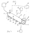
- FIG. 3 An alternative embodiment 10a is shown in Fig. 3 which eliminates the adjustable vertical supports 13, 14. Instead, a plurality of pairs of fixed, non-conductive rollers, one roller of each pair shown at 24a, 26a, supports the tube 12 during the resistance heating thereof.
- Suitable alloys for casting in accordance with the above-described methods include nickel alloys.
- Nickel-chromium alloys can generally be used as corrosion-resistant alloys and tungsten-carbon-nickel alloys can be generally used as abrasion resistant alloys.
- Suitable casing materials include alloy steels which all have sufficiently high melting points and resistant values.
- the amount of current required to carry out the resistance heating of the tubing 12 will vary depending upon the materials of construction for the tubing and the thickness of the tubing.
- the time required for the heating step will also vary greatly, depending upon the tubing alloy, the thickness of the tubing and the length of the tubing.
- the time required to carry out the spinning step will also vary depending upon the amount of alloy needed to satisfactorily coat the interior surface of the tubing.
- the length of the tubing 12 to be processed using the resistance heating methods and apparatuses disclosed above can vary greatly and will not be limited by the size of a furnace. Again, no furnace is required, just the use of two electrodes mounted at opposing ends of the tubing. Further, it has been found that resistance heating is faster and therefore more economical than induction or radiant heating as taught by the prior art. Still further, as shown in Figs. 1 and 2, quenching or cooling equipment may be easily integrated in a space-efficient manner.
Landscapes
- Chemical & Material Sciences (AREA)
- Organic Chemistry (AREA)
- Engineering & Computer Science (AREA)
- Materials Engineering (AREA)
- Mechanical Engineering (AREA)
- Metallurgy (AREA)
- Chemical Kinetics & Catalysis (AREA)
- Other Surface Treatments For Metallic Materials (AREA)
- Coating By Spraying Or Casting (AREA)
- Heat Treatment Of Articles (AREA)
- Coating With Molten Metal (AREA)
- Application Of Or Painting With Fluid Materials (AREA)
- Organic Low-Molecular-Weight Compounds And Preparation Thereof (AREA)
Claims (31)
- Procédé pour revêtir une surface interne d'un tube métallique disposé horizontalement avec un premier alliage, le tube comprenant au moins une extrémité ouverte et une surface interne, le procédé comprenant les étapes suivantes :La mise en place d'une quantité d'un premier alliage dans le tube, le premier alliage se présentant sous forme solide choisie dans le groupe constitué d'une poudre, de grenailles et de pastilles ;la fermeture d'au moins une extrémité ouverte du tube par un chapeau ;le chauffage du tube par application, aux bornes du tube, d'un courant suffisant pour chauffer le tube et faire fondre le premier alliage ;l'abaissement du tube et du premier alliage vers un dispositif d'emboîtement comprenant deux paires de galets espacés l'un de l'autre le long d'un axe longitudinal du tube, le dispositif d'emboîtement fournissant un support horizontal pour le tube ; etla rotation d'au moins un desdits galets pour faire tourner le tube autour d'un axe longitudinal du tube afin de répartir le premier alliage fondu le long de la surface interne du tube.
- Procédé selon la revendication 1, dans lequel le chapeau comprend un mécanisme de libération de pression.
- Procédé selon la revendication 1, dans lequel le tube comprend un second alliage, le premier alliage ayant un point de fusion inférieur à celui du second alliage.
- Procédé selon la revendication 1, dans lequel le tube comprend un second alliage, les premier et second alliages étant solubles l'un dans l'autre.
- Procédé selon la revendication 1, dans lequel le tube métallique a une résistance électrique qui est supérieure à la résistance électrique du cuivre.
- Procédé selon la revendication 1, dans lequel le dispositif d'emboîtement est électriquement isolé.
- Procédé selon la revendication 1, dans lequel le chauffage du tube par application de courant aux bornes du tube comprend la connexion de deux électrodes au tube, les électrodes étant espacées l'une de l'autre de manière longitudinale le long du tube.
- Procédé selon la revendication 7, dans lequel le tube est maintenu en place par un support horizontal pendant le chauffage du tube par application d'un courant aux bornes du tube et le procédé comprend en outre :l'abaissement du support horizontal pour placer le tube et le premier alliage sur un dispositif d'emboîtement entre le chauffage et la rotation du tube et du premier alliage.
- Procédé selon la revendication 8, dans lequel le dispositif d'emboîtement est électriquement isolé des électrodes.
- Procédé selon la revendication 7, dans lequel le tube est maintenu en place par des galets non conducteurs durant le chauffage du tube par application d'un courant aux bornes du tube.
- Procédé selon la revendication 1, comprenant en outre la mise en place de graphite dans le tube avec le premier alliage.
- Procédé selon la revendication 2, dans lequel le chapeau est un chapeau aéré.
- Procédé selon la revendication 2, dans lequel le chapeau comprend un trou pour libérer le gaz.
- Procédé selon la revendication 1, comprenant en outre l'écoulement de gaz inerte dans le tube au cours du chauffage du tube.
- Procédé selon la revendication 1, comprenant en outre le refroidissement du tube et du premier alliage.
- Procédé selon la revendication 15, dans lequel le refroidissement comprend un écoulement d'air dans le tube pendant la rotation de celui-ci.
- Procédé selon la revendication 15, dans lequel le refroidissement comprend l'application d'un réfrigérant à l'extérieur du tube au cours de son refroidissement.
- Procédé selon la revendication 15, dans lequel le refroidissement comprend le trempage du tube et du premier alliage dans un réfrigérant après sa rotation.
- Procédé pour revêtir une surface interne d'un boîtier métallique disposé horizontalement avec un premier alliage, le boîtier comprenant deux extrémités ouvertes et une surface interne, le procédé comprenant les étapes suivantes :la mise en place d'une quantité suffisante d'un premier alliage pour revêtir la surface interne du boîtier ;la fermeture des deux extrémités ouvertes du boîtier par des chapeaux, au moins l'un des chapeaux comprenant un mécanisme de libération de pression ;le chauffage du boîtier en engageant deux électrodes espacées longitudinalement l'une de l'autre sur le boîtier et en appliquant, aux bornes du boîtier, un courant suffisant pour chauffer le boîtier et faire fondre le premier alliage ;la rotation du boîtier sur une pluralité de paires de galets autour d'un axe longitudinal du boîtier disposé horizontalement pour répartir le premier alliage fondu le long de la surface interne du boîtier ; etle refroidissement du boîtier et du premier alliage.
- Procédé selon la revendication 19, dans lequel le boîtier comprend un second alliage, les premier et second alliages étant solubles l'un dans l'autre.
- Procédé selon la revendication 19, dans lequel les galets sont électriquement isolés des électrodes.
- Procédé selon la revendication 19, comprenant en outre l'écoulement de gaz inerte dans le boîtier au cours du chauffage du boîtier.
- Procédé selon la revendication 20, dans lequel le refroidissement comprend le trempage du tube et du premier alliage dans un réfrigérant après sa rotation.
- Procédé pour revêtir la surface interne d'un boîtier métallique disposé horizontalement avec un premier alliage, le boîtier comprenant deux extrémités ouvertes et une surface interne, le procédé comprenant les étapes suivantes :La mise en place d'une quantité suffisante d'un premier alliage dans le boîtier pour revêtir la surface interne du boîtier, le premier alliage se présentant en forme solide choisie dans le groupe constitué d'une poudre, de grenailles et de pastilles ;la fermeture des deux extrémités ouvertes du boîtier par des chapeaux, au moins l'un des chapeaux comprenant un mécanisme de libération de pression ;l'abaissement du tube et du premier alliage vers un dispositif d'emboîtement comprenant deux paires de galets espacées l'une de l'autre le long d'un axe longitudinal du tube, le dispositif d'emboîtement fournissant un support horizontal pour le boîtier ;le chauffage du boîtier en engageant deux électrodes espacées longitudinalement l'une de l'autre sur le boîtier et en appliquant, aux bornes du boîtier, un courant suffisant pour chauffer le boîtier et faire fondre le premier alliage ;la rotation du boîtier sur les galets autour d'un axe longitudinal du boîtier pour répartir le premier alliage fondu le long de la surface interne du boîtier tout en continuant à chauffer le boîtier en appliquant ledit courant suffisant aux bornes du boîtier ; etle refroidissement du boîtier et du premier alliage.
- Appareil pour revêtir un intérieur d'un tube métallique avec un alliage, le tube comprenant des extrémités ouvertes, l'appareil comprenant :un support ajustable verticalement pour supporter le tube métallique en position horizontale ;une pluralité de paires de galets espacés l'un de l'autre dans l'alignement avec le support pour recevoir le tube lorsque le support est abaissé et pour encore supporter le tube en position horizontale, au moins un galet de la pluralité de paires de galets étant relié à un mécanisme d'entraînement pour faire tourner ledit au moins un galet et communiquer une rotation au tube ;deux électrodes pour une connexion amovible avec les extrémités opposées du tube ; etdeux chapeaux pour fermer les extrémités ouvertes opposées du tube, au moins l'un des chapeaux étant aéré.
- Appareil selon la revendication 25, comprenant en outre une alimentation en gaz inerte raccordée à l'un des chapeaux.
- Appareil selon la revendication 25, comprenant en outre une alimentation en réfrigérant raccordée à un dispositif de pulvérisation pour appliquer le réfrigérant au tube.
- Appareil selon la revendication 25, comprenant en outre une cuve de trempe au moins partiellement remplie de réfrigérant.
- Appareil pour revêtir un intérieur d'un tube métallique avec un alliage, le tube comprenant des extrémités ouvertes opposées, l'appareil comprenant :une pluralité de paires de galets non conducteurs espacés l'un de l'autre dans l'alignement pour recevoir le tube et supporter le tube en position horizontale, au moins un galet de la pluralité de paires de galets étant relié à un mécanisme d'entraînement pour faire tourner ledit au moins un galet et communiquer la rotation au tube ;deux électrodes pour une connexion amovible aux extrémités opposées du tube ; etdeux chapeaux pour fermer les extrémités ouvertes opposées du tube, au moins l'un des chapeaux étant aéré.
- Appareil selon la revendication 29, comprenant en outre une alimentation en gaz inerte raccordée à l'un des chapeaux.
- Appareil selon la revendication 29, comprenant en outre une alimentation en réfrigérant raccordée à un dispositif de pulvérisation pour appliquer le réfrigérant au tube.
Applications Claiming Priority (3)
| Application Number | Priority Date | Filing Date | Title |
|---|---|---|---|
| US10/189,118 US6635317B1 (en) | 2002-07-02 | 2002-07-02 | Method for coating metallic tubes with corrosion-resistant alloys |
| US189118 | 2002-07-02 | ||
| PCT/US2003/019821 WO2004004923A2 (fr) | 2002-07-02 | 2003-06-23 | Procede permettant d'appliquer des alliages anticorrosion sur des tubes metalliques |
Publications (2)
| Publication Number | Publication Date |
|---|---|
| EP1520061A2 EP1520061A2 (fr) | 2005-04-06 |
| EP1520061B1 true EP1520061B1 (fr) | 2008-01-09 |
Family
ID=28791605
Family Applications (1)
| Application Number | Title | Priority Date | Filing Date |
|---|---|---|---|
| EP03763016A Expired - Lifetime EP1520061B1 (fr) | 2002-07-02 | 2003-06-23 | Procede permettant d'appliquer des alliages anticorrosion sur des tubes metalliques |
Country Status (6)
| Country | Link |
|---|---|
| US (1) | US6635317B1 (fr) |
| EP (1) | EP1520061B1 (fr) |
| AT (1) | ATE383457T1 (fr) |
| AU (1) | AU2003243751A1 (fr) |
| DE (1) | DE60318576T2 (fr) |
| WO (1) | WO2004004923A2 (fr) |
Family Cites Families (29)
| Publication number | Priority date | Publication date | Assignee | Title |
|---|---|---|---|---|
| US2046914A (en) | 1935-05-17 | 1936-07-07 | Ind Res Lab Ltd | Hard ferrous-lined tube |
| US2178419A (en) * | 1936-12-11 | 1939-10-31 | Gen Electric | Method and apparatus for coating vitreous tubes |
| US2470689A (en) * | 1943-02-16 | 1949-05-17 | Chase Brass & Copper Co | Process for tin-coating the interiors of copper tubes |
| US2880109A (en) * | 1955-09-22 | 1959-03-31 | United States Steel Corp | Method of coating the interior of cylinders |
| US3007810A (en) | 1958-12-31 | 1961-11-07 | Bundy Tubing Co | Method and apparatus for coating a tube interior |
| US3056692A (en) | 1959-07-30 | 1962-10-02 | Kitada Kohshiro | Method for the manufacture of a mold for centrifugal casting tubular metal articles |
| US3392009A (en) * | 1965-10-23 | 1968-07-09 | Union Carbide Corp | Method of producing low carbon, non-aging, deep drawing steel |
| JPS4958123A (fr) | 1972-10-06 | 1974-06-05 | ||
| US4382421A (en) | 1980-04-11 | 1983-05-10 | Vetco, Inc. | Tube coating apparatus |
| JPS57495A (en) * | 1980-06-03 | 1982-01-05 | Sumitomo Electric Ind Ltd | Manufacture of heat exchanger |
| US4408561A (en) * | 1981-08-24 | 1983-10-11 | Nippon Steel Corporation | Dual-purpose plant for producing cold rolled steel sheet and hot-dip galvanized steel sheet |
| DE3141919C2 (de) * | 1981-10-22 | 1984-05-17 | Heraeus Quarzschmelze Gmbh, 6450 Hanau | Verfahren zur Herstellung eines rohrförmigen Verbundkörpers |
| JPS58117875A (ja) * | 1982-01-06 | 1983-07-13 | Mitsubishi Heavy Ind Ltd | シリンダ素材の内面処理方法 |
| JPS58141388A (ja) * | 1982-02-15 | 1983-08-22 | Mitsubishi Heavy Ind Ltd | シリンダの製造方法 |
| US4490411A (en) | 1983-03-14 | 1984-12-25 | Darryl Feder | Apparatus for and method of metalizing internal surfaces of metal bodies such as tubes and pipes |
| JPS60255984A (ja) * | 1984-05-30 | 1985-12-17 | Mitsubishi Metal Corp | 熱交換体の製造方法 |
| JPS60255983A (ja) * | 1984-05-30 | 1985-12-17 | Mitsubishi Metal Corp | 熱交換体の製造方法 |
| JPS6123772A (ja) * | 1984-07-09 | 1986-02-01 | Dai Ichi High Frequency Co Ltd | 金属管等の内面に金属ライニングを施す方法 |
| JPS6141780A (ja) * | 1984-07-31 | 1986-02-28 | Mie Kounetsu Kk | 管状金属素材の内面に窯業材料を融着させる方法並びに装置 |
| US4869203A (en) | 1988-07-18 | 1989-09-26 | Vapor Technologies Inc. | Apparatus for coating a metal gas-pressure bottle or tank |
| US5059453A (en) | 1990-03-08 | 1991-10-22 | Inductametals Corporation | Method and apparatus for metalizing internal surfaces of metal bodies such as tubes and pipes |
| US5413638A (en) | 1990-10-03 | 1995-05-09 | Bernstein, Jr.; Philip | Apparatus for metalizing internal surfaces of tubular metal bodies |
| US5202160A (en) * | 1991-05-24 | 1993-04-13 | Inductametals Corporation | Holdback control in apparatus for coating the internal surfaces of metal tubes |
| JPH07140824A (ja) * | 1993-11-19 | 1995-06-02 | Oki Electric Ind Co Ltd | 加熱定着装置 |
| US5618591A (en) | 1995-05-15 | 1997-04-08 | Fuse Co. | Method of coating an inside of a pipe or tube |
| US5558150A (en) | 1995-05-26 | 1996-09-24 | Erim | Method of producing a cast multilayered alloy tube and the product thereof |
| US6019845A (en) | 1998-04-23 | 2000-02-01 | Nakakoshi; Senkichi | Method for coating inner surfaces of metal tubes with powdery paint and apparatus therefor |
| US6197437B1 (en) * | 1999-02-22 | 2001-03-06 | Wall Colmonoy Corporation | Casting alloys and method of making composite barrels used in extrusion and injection molding |
| DE10064384A1 (de) * | 2000-12-05 | 2002-06-13 | Euromat Ges Fuer Werkstofftech | Werkstück mit einem Hohlraum sowie Verfahren zur Erzeugung einer verschleissfesten Beschichtung darin |
-
2002
- 2002-07-02 US US10/189,118 patent/US6635317B1/en not_active Expired - Lifetime
-
2003
- 2003-06-23 AT AT03763016T patent/ATE383457T1/de active
- 2003-06-23 WO PCT/US2003/019821 patent/WO2004004923A2/fr not_active Ceased
- 2003-06-23 DE DE60318576T patent/DE60318576T2/de not_active Expired - Lifetime
- 2003-06-23 EP EP03763016A patent/EP1520061B1/fr not_active Expired - Lifetime
- 2003-06-23 AU AU2003243751A patent/AU2003243751A1/en not_active Abandoned
Also Published As
| Publication number | Publication date |
|---|---|
| WO2004004923A2 (fr) | 2004-01-15 |
| EP1520061A2 (fr) | 2005-04-06 |
| WO2004004923B1 (fr) | 2004-04-08 |
| WO2004004923A3 (fr) | 2004-02-26 |
| WO2004004923A9 (fr) | 2004-05-21 |
| DE60318576T2 (de) | 2009-02-19 |
| AU2003243751A1 (en) | 2004-01-23 |
| DE60318576D1 (de) | 2008-02-21 |
| US6635317B1 (en) | 2003-10-21 |
| AU2003243751A8 (en) | 2004-01-23 |
| ATE383457T1 (de) | 2008-01-15 |
Similar Documents
| Publication | Publication Date | Title |
|---|---|---|
| US6719034B2 (en) | Process for producing a tube-shaped cathode sputtering target | |
| US8735783B2 (en) | Electric induction heating and stirring of an electrically conductive material in a containment vessel | |
| CN104148599B (zh) | 一种包覆材料固/液复合水平连铸成形设备与方法 | |
| CN104148598B (zh) | 一种包覆材料固/液复合双重凝固连铸成形设备与方法 | |
| CN110124957A (zh) | 一种管道内壁高频感应熔覆的装置及方法 | |
| CN110396651B (zh) | 碳纤维增强铝基复合材料的制备系统、复合材料以及零部件 | |
| EP2518027A2 (fr) | Support d'électrode de fusion de verre électrique | |
| CN104778997A (zh) | 一种高温高导电工线材及其制备方法 | |
| CN109894590A (zh) | 一种大直径铜合金管的连铸设备和方法 | |
| EP1520061B1 (fr) | Procede permettant d'appliquer des alliages anticorrosion sur des tubes metalliques | |
| JPH0813111A (ja) | 溶融亜鉛めっき装置 | |
| CN204100794U (zh) | 非晶合金用的洁净熔融系统 | |
| JP2914863B2 (ja) | 誘導加熱メニスカス被覆用溶融金属容器及び被覆ライン | |
| CN108203798B (zh) | 连续制备金属复合线材的方法和装置 | |
| US10385436B2 (en) | Molten metal plating furnace, system for producing and method for producing plated product, and metal plated steel tube obtained by means of said method for producing | |
| CN206882738U (zh) | 一种自熔式非晶合金制带机的自熔喷包结构 | |
| JP4197834B2 (ja) | 溶融金属含浸方法 | |
| CN108247021B (zh) | 一种预热自耗电极生产复合轧辊的电渣重熔装置及其方法 | |
| CN106392385B (zh) | 焊条不锈钢丝生产工艺 | |
| SE503968C2 (sv) | Kapsel för utbränt kärnbränsle samt förfarande vid framställning av sådan kapsel | |
| CN212713842U (zh) | 一种用于制备管状晶体材料的加热装置 | |
| US6736187B2 (en) | Molten metal infiltrating method and molten metal infiltrating apparatus | |
| CN222274651U (zh) | 一种金属丝热熔浸镀装置 | |
| CN205856579U (zh) | 一种碳化硅气加热镀锌套管 | |
| CN209602109U (zh) | 还原炉 |
Legal Events
| Date | Code | Title | Description |
|---|---|---|---|
| PUAI | Public reference made under article 153(3) epc to a published international application that has entered the european phase |
Free format text: ORIGINAL CODE: 0009012 |
|
| 17P | Request for examination filed |
Effective date: 20050201 |
|
| AK | Designated contracting states |
Kind code of ref document: A2 Designated state(s): AT BE BG CH CY CZ DE DK EE ES FI FR GB GR HU IE IT LI LU MC NL PT RO SE SI SK TR |
|
| AX | Request for extension of the european patent |
Extension state: AL LT LV MK |
|
| DAX | Request for extension of the european patent (deleted) | ||
| GRAP | Despatch of communication of intention to grant a patent |
Free format text: ORIGINAL CODE: EPIDOSNIGR1 |
|
| GRAS | Grant fee paid |
Free format text: ORIGINAL CODE: EPIDOSNIGR3 |
|
| GRAA | (expected) grant |
Free format text: ORIGINAL CODE: 0009210 |
|
| AK | Designated contracting states |
Kind code of ref document: B1 Designated state(s): AT BE BG CH CY CZ DE DK EE ES FI FR GB GR HU IE IT LI LU MC NL PT RO SE SI SK TR |
|
| REG | Reference to a national code |
Ref country code: GB Ref legal event code: FG4D |
|
| REG | Reference to a national code |
Ref country code: CH Ref legal event code: EP |
|
| REG | Reference to a national code |
Ref country code: IE Ref legal event code: FG4D |
|
| REF | Corresponds to: |
Ref document number: 60318576 Country of ref document: DE Date of ref document: 20080221 Kind code of ref document: P |
|
| PG25 | Lapsed in a contracting state [announced via postgrant information from national office to epo] |
Ref country code: SI Free format text: LAPSE BECAUSE OF FAILURE TO SUBMIT A TRANSLATION OF THE DESCRIPTION OR TO PAY THE FEE WITHIN THE PRESCRIBED TIME-LIMIT Effective date: 20080109 |
|
| PG25 | Lapsed in a contracting state [announced via postgrant information from national office to epo] |
Ref country code: CH Free format text: LAPSE BECAUSE OF FAILURE TO SUBMIT A TRANSLATION OF THE DESCRIPTION OR TO PAY THE FEE WITHIN THE PRESCRIBED TIME-LIMIT Effective date: 20080109 Ref country code: ES Free format text: LAPSE BECAUSE OF FAILURE TO SUBMIT A TRANSLATION OF THE DESCRIPTION OR TO PAY THE FEE WITHIN THE PRESCRIBED TIME-LIMIT Effective date: 20080420 Ref country code: FI Free format text: LAPSE BECAUSE OF FAILURE TO SUBMIT A TRANSLATION OF THE DESCRIPTION OR TO PAY THE FEE WITHIN THE PRESCRIBED TIME-LIMIT Effective date: 20080109 Ref country code: LI Free format text: LAPSE BECAUSE OF FAILURE TO SUBMIT A TRANSLATION OF THE DESCRIPTION OR TO PAY THE FEE WITHIN THE PRESCRIBED TIME-LIMIT Effective date: 20080109 |
|
| REG | Reference to a national code |
Ref country code: CH Ref legal event code: PL |
|
| PG25 | Lapsed in a contracting state [announced via postgrant information from national office to epo] |
Ref country code: BG Free format text: LAPSE BECAUSE OF FAILURE TO SUBMIT A TRANSLATION OF THE DESCRIPTION OR TO PAY THE FEE WITHIN THE PRESCRIBED TIME-LIMIT Effective date: 20080409 |
|
| ET | Fr: translation filed | ||
| PG25 | Lapsed in a contracting state [announced via postgrant information from national office to epo] |
Ref country code: PT Free format text: LAPSE BECAUSE OF FAILURE TO SUBMIT A TRANSLATION OF THE DESCRIPTION OR TO PAY THE FEE WITHIN THE PRESCRIBED TIME-LIMIT Effective date: 20080609 |
|
| PG25 | Lapsed in a contracting state [announced via postgrant information from national office to epo] |
Ref country code: CZ Free format text: LAPSE BECAUSE OF FAILURE TO SUBMIT A TRANSLATION OF THE DESCRIPTION OR TO PAY THE FEE WITHIN THE PRESCRIBED TIME-LIMIT Effective date: 20080109 Ref country code: DK Free format text: LAPSE BECAUSE OF FAILURE TO SUBMIT A TRANSLATION OF THE DESCRIPTION OR TO PAY THE FEE WITHIN THE PRESCRIBED TIME-LIMIT Effective date: 20080109 Ref country code: SE Free format text: LAPSE BECAUSE OF FAILURE TO SUBMIT A TRANSLATION OF THE DESCRIPTION OR TO PAY THE FEE WITHIN THE PRESCRIBED TIME-LIMIT Effective date: 20080409 Ref country code: SK Free format text: LAPSE BECAUSE OF FAILURE TO SUBMIT A TRANSLATION OF THE DESCRIPTION OR TO PAY THE FEE WITHIN THE PRESCRIBED TIME-LIMIT Effective date: 20080109 |
|
| PLBE | No opposition filed within time limit |
Free format text: ORIGINAL CODE: 0009261 |
|
| STAA | Information on the status of an ep patent application or granted ep patent |
Free format text: STATUS: NO OPPOSITION FILED WITHIN TIME LIMIT |
|
| PG25 | Lapsed in a contracting state [announced via postgrant information from national office to epo] |
Ref country code: RO Free format text: LAPSE BECAUSE OF FAILURE TO SUBMIT A TRANSLATION OF THE DESCRIPTION OR TO PAY THE FEE WITHIN THE PRESCRIBED TIME-LIMIT Effective date: 20080109 |
|
| 26N | No opposition filed |
Effective date: 20081010 |
|
| BERE | Be: lapsed |
Owner name: CASNER JR., KENNETH Effective date: 20080630 |
|
| PG25 | Lapsed in a contracting state [announced via postgrant information from national office to epo] |
Ref country code: MC Free format text: LAPSE BECAUSE OF NON-PAYMENT OF DUE FEES Effective date: 20080630 |
|
| PG25 | Lapsed in a contracting state [announced via postgrant information from national office to epo] |
Ref country code: BE Free format text: LAPSE BECAUSE OF NON-PAYMENT OF DUE FEES Effective date: 20080630 |
|
| PG25 | Lapsed in a contracting state [announced via postgrant information from national office to epo] |
Ref country code: IE Free format text: LAPSE BECAUSE OF NON-PAYMENT OF DUE FEES Effective date: 20080623 Ref country code: EE Free format text: LAPSE BECAUSE OF FAILURE TO SUBMIT A TRANSLATION OF THE DESCRIPTION OR TO PAY THE FEE WITHIN THE PRESCRIBED TIME-LIMIT Effective date: 20080109 |
|
| PG25 | Lapsed in a contracting state [announced via postgrant information from national office to epo] |
Ref country code: CY Free format text: LAPSE BECAUSE OF FAILURE TO SUBMIT A TRANSLATION OF THE DESCRIPTION OR TO PAY THE FEE WITHIN THE PRESCRIBED TIME-LIMIT Effective date: 20080109 |
|
| PGFP | Annual fee paid to national office [announced via postgrant information from national office to epo] |
Ref country code: NL Payment date: 20090603 Year of fee payment: 7 |
|
| PG25 | Lapsed in a contracting state [announced via postgrant information from national office to epo] |
Ref country code: IT Free format text: LAPSE BECAUSE OF FAILURE TO SUBMIT A TRANSLATION OF THE DESCRIPTION OR TO PAY THE FEE WITHIN THE PRESCRIBED TIME-LIMIT Effective date: 20080109 |
|
| PGFP | Annual fee paid to national office [announced via postgrant information from national office to epo] |
Ref country code: GB Payment date: 20090617 Year of fee payment: 7 |
|
| PG25 | Lapsed in a contracting state [announced via postgrant information from national office to epo] |
Ref country code: LU Free format text: LAPSE BECAUSE OF NON-PAYMENT OF DUE FEES Effective date: 20080623 Ref country code: HU Free format text: LAPSE BECAUSE OF FAILURE TO SUBMIT A TRANSLATION OF THE DESCRIPTION OR TO PAY THE FEE WITHIN THE PRESCRIBED TIME-LIMIT Effective date: 20080710 |
|
| PG25 | Lapsed in a contracting state [announced via postgrant information from national office to epo] |
Ref country code: TR Free format text: LAPSE BECAUSE OF FAILURE TO SUBMIT A TRANSLATION OF THE DESCRIPTION OR TO PAY THE FEE WITHIN THE PRESCRIBED TIME-LIMIT Effective date: 20080109 |
|
| PG25 | Lapsed in a contracting state [announced via postgrant information from national office to epo] |
Ref country code: GR Free format text: LAPSE BECAUSE OF FAILURE TO SUBMIT A TRANSLATION OF THE DESCRIPTION OR TO PAY THE FEE WITHIN THE PRESCRIBED TIME-LIMIT Effective date: 20080410 |
|
| REG | Reference to a national code |
Ref country code: NL Ref legal event code: V1 Effective date: 20110101 |
|
| GBPC | Gb: european patent ceased through non-payment of renewal fee |
Effective date: 20100623 |
|
| PG25 | Lapsed in a contracting state [announced via postgrant information from national office to epo] |
Ref country code: NL Free format text: LAPSE BECAUSE OF NON-PAYMENT OF DUE FEES Effective date: 20110101 |
|
| PG25 | Lapsed in a contracting state [announced via postgrant information from national office to epo] |
Ref country code: GB Free format text: LAPSE BECAUSE OF NON-PAYMENT OF DUE FEES Effective date: 20100623 |
|
| PGFP | Annual fee paid to national office [announced via postgrant information from national office to epo] |
Ref country code: AT Payment date: 20120529 Year of fee payment: 10 |
|
| PGFP | Annual fee paid to national office [announced via postgrant information from national office to epo] |
Ref country code: DE Payment date: 20130619 Year of fee payment: 11 |
|
| PGFP | Annual fee paid to national office [announced via postgrant information from national office to epo] |
Ref country code: FR Payment date: 20130624 Year of fee payment: 11 |
|
| REG | Reference to a national code |
Ref country code: DE Ref legal event code: R119 Ref document number: 60318576 Country of ref document: DE |
|
| REG | Reference to a national code |
Ref country code: AT Ref legal event code: MM01 Ref document number: 383457 Country of ref document: AT Kind code of ref document: T Effective date: 20140623 |
|
| REG | Reference to a national code |
Ref country code: FR Ref legal event code: ST Effective date: 20150227 |
|
| REG | Reference to a national code |
Ref country code: DE Ref legal event code: R119 Ref document number: 60318576 Country of ref document: DE Effective date: 20150101 |
|
| PG25 | Lapsed in a contracting state [announced via postgrant information from national office to epo] |
Ref country code: DE Free format text: LAPSE BECAUSE OF NON-PAYMENT OF DUE FEES Effective date: 20150101 |
|
| PG25 | Lapsed in a contracting state [announced via postgrant information from national office to epo] |
Ref country code: FR Free format text: LAPSE BECAUSE OF NON-PAYMENT OF DUE FEES Effective date: 20140630 Ref country code: AT Free format text: LAPSE BECAUSE OF NON-PAYMENT OF DUE FEES Effective date: 20140623 |