EP1520099B1 - Injecteur de carburant a multiplicateur de pression a reduction de pression rapide lors de l'injection - Google Patents
Injecteur de carburant a multiplicateur de pression a reduction de pression rapide lors de l'injection Download PDFInfo
- Publication number
- EP1520099B1 EP1520099B1 EP03722254A EP03722254A EP1520099B1 EP 1520099 B1 EP1520099 B1 EP 1520099B1 EP 03722254 A EP03722254 A EP 03722254A EP 03722254 A EP03722254 A EP 03722254A EP 1520099 B1 EP1520099 B1 EP 1520099B1
- Authority
- EP
- European Patent Office
- Prior art keywords
- pressure
- valve
- space
- relief valve
- booster
- Prior art date
- Legal status (The legal status is an assumption and is not a legal conclusion. Google has not performed a legal analysis and makes no representation as to the accuracy of the status listed.)
- Expired - Lifetime
Links
- 239000000446 fuel Substances 0.000 title claims description 90
- 238000002347 injection Methods 0.000 title claims description 83
- 239000007924 injection Substances 0.000 title claims description 83
- 230000009467 reduction Effects 0.000 title claims description 9
- 238000002485 combustion reaction Methods 0.000 claims description 37
- 230000006835 compression Effects 0.000 claims description 25
- 238000007906 compression Methods 0.000 claims description 25
- 238000007789 sealing Methods 0.000 claims description 6
- 239000000243 solution Substances 0.000 description 7
- 238000003860 storage Methods 0.000 description 4
- 238000013016 damping Methods 0.000 description 3
- 239000012530 fluid Substances 0.000 description 3
- 238000000034 method Methods 0.000 description 3
- 230000008569 process Effects 0.000 description 3
- 230000010349 pulsation Effects 0.000 description 3
- 230000009471 action Effects 0.000 description 2
- 230000007423 decrease Effects 0.000 description 2
- 239000002828 fuel tank Substances 0.000 description 2
- 238000004519 manufacturing process Methods 0.000 description 2
- 230000004913 activation Effects 0.000 description 1
- 238000006243 chemical reaction Methods 0.000 description 1
- 238000010586 diagram Methods 0.000 description 1
- 230000000694 effects Effects 0.000 description 1
- 238000005516 engineering process Methods 0.000 description 1
- 230000004048 modification Effects 0.000 description 1
- 238000012986 modification Methods 0.000 description 1
- 238000003825 pressing Methods 0.000 description 1
- 238000000926 separation method Methods 0.000 description 1
Images


Classifications
-
- F—MECHANICAL ENGINEERING; LIGHTING; HEATING; WEAPONS; BLASTING
- F02—COMBUSTION ENGINES; HOT-GAS OR COMBUSTION-PRODUCT ENGINE PLANTS
- F02M—SUPPLYING COMBUSTION ENGINES IN GENERAL WITH COMBUSTIBLE MIXTURES OR CONSTITUENTS THEREOF
- F02M57/00—Fuel-injectors combined or associated with other devices
- F02M57/02—Injectors structurally combined with fuel-injection pumps
- F02M57/022—Injectors structurally combined with fuel-injection pumps characterised by the pump drive
- F02M57/025—Injectors structurally combined with fuel-injection pumps characterised by the pump drive hydraulic, e.g. with pressure amplification
- F02M57/026—Construction details of pressure amplifiers, e.g. fuel passages or check valves arranged in the intensifier piston or head, particular diameter relationships, stop members, arrangement of ports or conduits
-
- F—MECHANICAL ENGINEERING; LIGHTING; HEATING; WEAPONS; BLASTING
- F02—COMBUSTION ENGINES; HOT-GAS OR COMBUSTION-PRODUCT ENGINE PLANTS
- F02M—SUPPLYING COMBUSTION ENGINES IN GENERAL WITH COMBUSTIBLE MIXTURES OR CONSTITUENTS THEREOF
- F02M45/00—Fuel-injection apparatus characterised by having a cyclic delivery of specific time/pressure or time/quantity relationship
-
- F—MECHANICAL ENGINEERING; LIGHTING; HEATING; WEAPONS; BLASTING
- F02—COMBUSTION ENGINES; HOT-GAS OR COMBUSTION-PRODUCT ENGINE PLANTS
- F02M—SUPPLYING COMBUSTION ENGINES IN GENERAL WITH COMBUSTIBLE MIXTURES OR CONSTITUENTS THEREOF
- F02M47/00—Fuel-injection apparatus operated cyclically with fuel-injection valves actuated by fluid pressure
- F02M47/02—Fuel-injection apparatus operated cyclically with fuel-injection valves actuated by fluid pressure of accumulator-injector type, i.e. having fuel pressure of accumulator tending to open, and fuel pressure in other chamber tending to close, injection valves and having means for periodically releasing that closing pressure
- F02M47/027—Electrically actuated valves draining the chamber to release the closing pressure
-
- F—MECHANICAL ENGINEERING; LIGHTING; HEATING; WEAPONS; BLASTING
- F02—COMBUSTION ENGINES; HOT-GAS OR COMBUSTION-PRODUCT ENGINE PLANTS
- F02M—SUPPLYING COMBUSTION ENGINES IN GENERAL WITH COMBUSTIBLE MIXTURES OR CONSTITUENTS THEREOF
- F02M57/00—Fuel-injectors combined or associated with other devices
- F02M57/02—Injectors structurally combined with fuel-injection pumps
- F02M57/022—Injectors structurally combined with fuel-injection pumps characterised by the pump drive
- F02M57/025—Injectors structurally combined with fuel-injection pumps characterised by the pump drive hydraulic, e.g. with pressure amplification
-
- F—MECHANICAL ENGINEERING; LIGHTING; HEATING; WEAPONS; BLASTING
- F02—COMBUSTION ENGINES; HOT-GAS OR COMBUSTION-PRODUCT ENGINE PLANTS
- F02M—SUPPLYING COMBUSTION ENGINES IN GENERAL WITH COMBUSTIBLE MIXTURES OR CONSTITUENTS THEREOF
- F02M59/00—Pumps specially adapted for fuel-injection and not provided for in groups F02M39/00 -F02M57/00, e.g. rotary cylinder-block type of pumps
- F02M59/02—Pumps specially adapted for fuel-injection and not provided for in groups F02M39/00 -F02M57/00, e.g. rotary cylinder-block type of pumps of reciprocating-piston or reciprocating-cylinder type
- F02M59/10—Pumps specially adapted for fuel-injection and not provided for in groups F02M39/00 -F02M57/00, e.g. rotary cylinder-block type of pumps of reciprocating-piston or reciprocating-cylinder type characterised by the piston-drive
- F02M59/105—Pumps specially adapted for fuel-injection and not provided for in groups F02M39/00 -F02M57/00, e.g. rotary cylinder-block type of pumps of reciprocating-piston or reciprocating-cylinder type characterised by the piston-drive hydraulic drive
Definitions
- both pressure-controlled and stroke-controlled injection systems can be used.
- fuel injection systems come next pump-injector units, pump-line-nozzle units and storage injection systems are used.
- Storage injection systems common rail injection systems
- the highest possible injection pressure is generally required.
- EP 0 562 046 B1 discloses a control and valve arrangement with damping for an electronically controlled injection unit.
- the actuation and valve assembly for a hydraulic unit comprises an electrically energizable electromagnet having a fixed stator and a movable armature.
- the anchor has a first and a second surface.
- the first and second surfaces of the armature define first and second cavities, with the first surface of the armature facing the stator.
- the valve is capable of delivering a hydraulic actuating fluid to the injector from a sump.
- a damping fluid may be collected therefrom with respect to one of the cavities of the solenoid assembly.
- WO 02/092997 A1 relates to a fuel injection device. This is used on an internal combustion engine.
- the combustion chambers of the internal combustion engine are each supplied with fuel via fuel injectors.
- the fuel injectors are acted upon by a high pressure source;
- the fuel injection device according to WO 02/092997 A1 comprises a pressure booster, which contains a movable pressure booster piston, which separates a connectable to the high pressure source chamber from a connected to the fuel injector high-pressure chamber.
- the fuel pressure in the high pressure chamber can be varied by filling a back space of the pressure booster with fuel or by emptying this back space of fuel.
- the fuel injector comprises a movable closing piston for opening or closing the injection openings facing the combustion chamber.
- the closing piston protrudes into a closing pressure chamber so that it can be pressurized with fuel. This achieves a force acting on the closing piston in the closing direction.
- the closing pressure chamber and another space are formed by a common working space, wherein all portions of the working space are permanently connected to each other for the exchange of fuel.
- a variable hydraulic closing force acting on the nozzle needle of the fuel injector can be achieved.
- a variable nozzle opening pressure is achieved, which increases with the pressure prevailing in the high-pressure reservoir, so that even with small amounts, a high injection pressure is achieved and the needle closing can be improved.
- the pressure prevailing in the high-pressure reservoir pressure is applied directly to the back of the nozzle needle.
- the pressure booster is controlled according to this solution on the back space, which then acts as a pressure booster control chamber.
- the proposed solution according to the invention avoids both the use of a designed as a 312-way valve control valve and the disadvantages associated with the use of a 2/2-way valve with Gudrossel or filling valve, d. H. a slower pressure drop towards the end of the injection.
- the filling throttle and the filling valve are replaced by a pressure relief valve, via which, however, a very rapid pressure reduction can be achieved at the end of an injection process.
- the rapid pressure reduction (rapid spill) at the end of the injection phase in turn significantly improves the emission levels of the exhaust gas of self-igniting internal combustion engines.
- the pressure relief valve is integrated in the control line to relieve the control chamber of the pressure booster.
- the valve body of the Druckentlasungsventils can be formed both as a cylindrical body and include an area which can be formed in a reduced diameter, for example as a constriction.
- the end faces of the valve body of the pressure relief valve can both be the same hydraulically effective surfaces and have different diameters.
- two opposing hydraulic chambers may be formed, which pass through a through hole in the valve body of the pressure relief valve communicate with each other.
- the flow cross section of the through bore within the valve body of the pressure relief valve is selected so that a pressure difference builds up between the hydraulic chambers of the pressure relief valve, so that the pressure relief valve can be kept closed.
- a metering valve designed as a 2/2-way valve By using a metering valve designed as a 2/2-way valve, it is possible to avoid the use of a 3/2-way valve that is expensive to produce and therefore expensive in terms of the required tolerance.
- the use of a pressure relief valve in the control line of the pressure booster allows a rapid pressure drop at the end of the injection, which can achieve a rapid closing of an example designed as a nozzle needle injection valve member.
- FIG. 1 shows a known pressure-intensified fuel injector with a parallel-connected filling valve and filling throttle, which has a slow pressure reduction behavior.
- the fuel injection device shown in Figure 1 comprises a fuel injector 1, and a high-pressure accumulator chamber 2 (common rail).
- the fuel injector 1 contains an injector body 3, a nozzle body 4, wherein a pressure booster 5 is received in the injector body 3 and a metering valve 6, which is formed in the arrangement shown in Figure 1 as a 2/2-way valve.
- high-pressure fuel is injected into a combustion chamber 7 of a self-igniting internal combustion engine.
- a fuel tank not shown, for. B. the fuel tank of a motor vehicle.
- the pressure booster 5 further comprises a control chamber 11 which is separated by a piston 12 from the working space 10 of the pressure booster 5.
- the piston 12 of the pressure booster 5 may be formed in one piece as well as in several parts.
- the piston 12 of the pressure booster comprises a first partial piston 13 and a second partial piston 14.
- the first partial piston 13 is formed in a first diameter
- a return spring 17 is received, which is supported on the one hand on an abutment 16 which is formed by the bottom of the control chamber 11 in the injector body 3, and on the other hand rests against the aforementioned return spring stop 18.
- the lower end face of the second partial piston 14 of the piston 12 acts on a compression chamber 15 of the pressure booster 5, which in turn passes through a fuel inlet 21 under high pressure fuel into a nozzle chamber 22 within the nozzle body 4 of the fuel injector 1.
- a throttle body 19 may be added, which serves to dampen when closing or opening of the fuel injector 1 adjusting pressure pulsations in the supply line 9, their unattenuated reaction in the interior the high pressure accumulator 2 there would have unacceptably high pressure peaks result.
- a throttle branch 36 extends to the working space 11 of the pressure booster 5, in which a Geardrossel 35 is added.
- a filling valve 37 is connected, which in the illustrated in Figure 1 Embodiment variant of a fuel injection device is designed as a ball valve with an opening spring.
- the filling valve 37 is parallel to the throttle point 35 in the throttle branch 36 and opens into the same line as the throttle branch 36, which in turn opens into the working space 11 of the pressure booster 5
- the control chamber 11 of the pressure booster 5 is connected via a control line 20 with the metering valve 6 in connection. From the control room 11 branches off beyond a connecting line 25, which in turn opens into a nozzle control chamber 24. A recorded in the nozzle control chamber 24 closing spring element 28 acts on an upper end face 27 of an injection valve member 26, which z. B. may be formed as a nozzle needle. Within the nozzle control chamber 24, a stop 29 is received, which is surrounded by the formed as a spiral spring closing spring element 28. From the nozzle control chamber 24 branches off a filling line 23, in which a check valve 34 is received. About the filling line 23 of the compression chamber 15 of the pressure booster 5 is filled with fuel.
- the nozzle body 4 of the fuel injector 1 receives a nozzle chamber 22 which is supplied via the aforementioned fuel inlet 21 from the compression chamber 15 with fuel under high pressure.
- the injection valve member 26 includes a pressure shoulder 30 which, when a high pressure is present within the nozzle chamber 22, moves the injection valve member 26 against the action of the closing spring 28 in the opening direction.
- From the nozzle chamber 22 extends within the nozzle body 4, an annular gap 32 in the direction of the tip 31 of the injection valve member 26. About the annular gap 32, the fuel flows to injection ports 33. About the injection openings 33 of the fuel at the open, d. H. From its combustion chamber side seat moving injection valve member 26 injected into the combustion chamber 7 of the self-igniting internal combustion engine.
- the variant of a fuel injection device shown in Figure 1 sets as a metering valve 6 a 2/2-way valve, which is provided to accelerate the return and to reduce the outflowing loss amount with a filling throttle 35 parallel valve 37.
- the arrangement shown in Figure 1 has the disadvantage that at the end of the injection process, a slow pressure drop to the pressure in the high-pressure reservoir 2 (common rail) present pressure level This leads to unsatisfactory emissions results, also by a slowly settling pressure reduction achievable average injection pressure decreases.
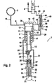
- Figure 2 shows an inventively designed, pressure-translated fuel injector with 2/2-way metering valve and a relief valve in the control line for controlling the pressure in the control chamber of the pressure booster.
- a pressure-intensified fuel injector 1 is shown, the metering valve 6 can be configured as 2/2-way valve, in the control line 20 to the control chamber 11 of the pressure booster 5 an additional, the filling throttle and the filling valve 37 replacing pressure relief valve 40 is integrated. With this configuration, a rapid spill can be achieved at the end of an injection process.
- the designed as a 2/2-way valve metering valve 6 is set in its closed position.
- the metering valve 6 can be designed as a directly operated valve or as a servo valve. Furthermore, the metering valve 6 can be actuated both by a magnetic actuator and by a piezoactuator.
- the hydraulic circuit diagram shown in FIG. 2 shows that the device for injecting fuel comprises a high-pressure reservoir 2 (common rail), which is supplied with fuel via a high-pressure pump (not shown in FIG. 2) which compresses the fuel to a high pressure level ,
- a high-pressure pump not shown in FIG. 2
- this is stored so that the fuel system pressure, d. H. the pressure prevailing in the interior of the high-pressure accumulator 2 pressure all fuel injectors 1, which are present in one of the number of cylinders of a self-igniting internal combustion engine corresponding number, can be supplied.
- the fuel injector 1 comprises the above-mentioned 2/2-way valve metering valve 6, a relief valve 40, received in the control line 20 between the control chamber 11 of the pressure booster 5 and the metering valve 6, the pressure booster 5 and an injection valve member.
- the pressure booster 5 is formed as an axially displaceable Kobenaji, a piston 12 formed by the piston 12, which may be formed integrally or in several parts, a working space 10 and a pressure relief or druckbeaufschlagbarer control chamber eleventh separated from each other.
- the piston 12 of the pressure booster 5 may comprise a first partial piston 13 and a second partial piston 14.
- the first sub-piston 13 may be formed in a larger diameter
- the second sub-piston 14 is formed in a contrast reduced diameter and applied to its lower end face a compression space 15 of the pressure booster.
- a supply line 9 extends to the working space 10 of the pressure booster 5, wherein in the supply line 9, a throttle point 19 may be formed to attenuate in the supply line 9 forming pressure pulsations or pressure wave reflections and their retroactive effect in the interior of the high-pressure accumulator 2.
- the metering valve 6 Im in 2 illustrated rest state of the device for injecting fuel is the metering valve 6, which is preferably designed as a 2/2-way valve, not activated and there is no injection instead.
- the pressure relief valve 40 received in the control line 20, 49 of the control chamber 11 of the pressure booster 5 is in its open initial state.
- switching state of the device for injecting fuel is pending in the interior of the high-pressure accumulator 2 pressure level in the working space 10 of the pressure booster 5, starting from this via an overflow 47 in a second space 42 of the pressure relief valve 40, via a in a valve body 43rd the pressure relief valve 40 formed overflow 44 in a first space 41 of the pressure relief valve 40 at.
- the prevailing pressure in the high-pressure reservoir 2 pressure level beyond the control line 20 in the control chamber 11 of the pressure booster 5, of this via the connecting line 25 in a nozzle control chamber 24 in the injector body 4 and a filling line 23 (filling path) is the in the interior of the high pressure accumulator 2 pending pressure in the compression chamber 15 of the pressure booster 5 at.
- the piston 12 of the pressure booster 5 is pressure balanced.
- the pressure booster 5 is deactivated in the idle state of the device for injecting fuel according to Figure 2 and there is no pressure gain instead.
- the piston 12 of the pressure booster 5 which may include a first part piston 13 and a second part piston 14, placed over a arranged in the control chamber 11 return spring element 17 in its initial position, the filling of the compression chamber 15 via the filling line 23, which differs from Nozzle control chamber 24, a check valve 34 containing the compression space 15 extends.
- the pressure relief valve 40 integrated in the control line 20, 49 between the metering valve 6 and the control chamber 11 comprises a substantially cylindrically shaped valve body 43.
- the cylindrical valve body 43 is penetrated by a through-bore 44.
- the through hole 44 connects the first space 41 with the second space 42 of the pressure relief valve 40.
- the substantially cylindrical valve body 46 may include a constriction 50.
- a valve spring 48 is received, which acts on an upper end face of the valve body 43.
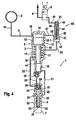
- FIG. 3 shows the pressure-translating fuel injector according to FIG. 2 in the activated state, that is to say in the activated state. H. with controlled 2/2-way valve.
- the metering of the fuel is effected by a control of the preferably designed as a 2/2-way valve metering valve 6.
- This can be controlled either via a piezoelectric actuator or a magnetic actuator;
- the metering valve 6 can also be designed as a servo valve or as a directly controlled valve.
- the valve body 43 of the pressure relief valve 40 closes with its slide portion 46, the valve cross section 45 by retracting against the action of the valve spring 48 in the direction of the first space 41.
- the pressure relief of the control chamber 11 is now via the control line 20 in the second space 42 of the pressure relief valve 40 and the formed in the valve body 43 through hole 44 in the low-pressure side return 8.
- the pressure in the nozzle control chamber 24 is reduced, as a result of which the pressure force acting in the closing direction on the end face 26 of the injection valve member 26 is reduced.
- the injection valve member 26, which is designed, for example, as a nozzle needle, opens in the nozzle chamber 22 by the hydraulic force applied to the pressure shoulder 30. The opening is thus pressure-controlled, so that fuel flows from the nozzle chamber 22 via the annular gap 32 surrounding the injection valve member 26 in the direction of the tip 31 of the injection valve member 26 flows and passes from there via the injection openings 33 into the combustion chamber 7 of the self-igniting internal combustion engine.
- the flow cross-section within the flow channel 44, which passes through the valve body 43 of the pressure relief valve 40 is designed such that a sufficient pressure difference between the first space 41 and the second space 42 of the pressure relief valve 40 sets, the valve body 43 of the pressure relief valve 40 in the closed position, d. H. the sliding portion 46 keeps in overlap with the valve cross-section 45, so that the overflow 47 remains closed in the pressure chamber 10 of the pressure booster.
- the control chamber 11 of the pressure booster 5 is separated from the low-pressure side return 8 by renewed activation of the metering valve 6 designed as a 2/2-way valve and again with the high-pressure reservoir 2 (Common rail) ruling high-pressure level connected. This is done by closing the metering valve designed as a 2/2-way valve 6.
- the connection to the low-pressure side return 8 is interrupted, whereby the flow of fuel through the flow channel 44 in the valve body 43 of the pressure relief valve 40 comes to a halt This is not effective in the closing direction Pressure difference between the first space 41 and the second space 42 of the pressure relief valve 40 form.
- valve spring 48 arranged in the first space 41 the valve body 43 with its second end face 43 and adjoining slide portion 46 on the valve body 43 is pressed into the second space 42 of the pressure relief valve 40.
- the slide portion 46 extends from the valve cross-section 45, so that the pending in the working space 10 of the pressure booster 5, the pressure in the high-pressure accumulator 2 corresponding pressure level on the overflow 47, the second space 42, the control line 20 again at the control chamber 11 of the pressure booster 5 is present , Due to the successful pressure equalization of the piston 12 of the pressure booster 5 moves into the working space 10, wherein its retraction is supported by the arranged in the control chamber 11 return spring element 17.
- the pressure level within the compression chamber 15 of the pressure booster 5 is lowered rapidly to the pressure prevailing in the high-pressure reservoir 2 pressure level.
- the injection valve member 26 configured as a nozzle needle, for example, is hydraulically balanced, ie the pressure level in the nozzle chamber 22 and in the nozzle control chamber 24 is identical.
- the closing force, which is exerted by the closing spring element 28 on the end face 27 of the injection valve member 26, outweighs and causes closing of the injection valve member 26, ie its retraction into its combustion chamber side seat.
- the injection ports 33 are closed in the region of the tip 31 of the injection valve member 26 and the injection is finished
- the pressure booster piston 12 After pressure equalization within the injection system in accordance with the configuration shown in FIG. 3, the pressure booster piston 12 is returned to its initial position by the return spring 17 acting on it. There is a refilling of the compression chamber 15 via the filling line 23 with in this integrated check valve 34 from the nozzle control chamber 24.
- the compression chamber 15 could also be filled from the hydraulic chambers 11 or 10.
- the nozzle control chamber 24 in turn is filled via the control chamber 11 of the pressure booster 5 via connecting line 25 with fuel.
- the fuel flows through the working space 10 of the pressure booster 5 via overflow 47, the second space 42 of the pressure relief valve 40 and the control line 20.
- the metering valve denoted by reference numeral 6 is preferably designed as a 2/2-way valve and can be manufactured particularly easily in the required tolerances manufacturing technology.
- the preferred as 2/2-way valve metering valve 6 can be performed both as a directly operated valve or as a servo-valve.
- the control of the 2/2-way metering valve 6 can be done both by a solenoid actuator and piezoelectric actuator.
- the pressure relief valve 40 may advantageously be designed so that no hydraulic pressure surface is present in relation to the pressure prevailing in the overflow line 47.
- the valve can be moved by a small spring force and a small pressure difference between the space 42 and the space 41 and only a small throttling of Abêtmenge in the bore 44 is necessary.
- a throttling in the overflow line 47 can also be arranged.
- the nozzle control chamber 24 may be connected instead of the control chamber 11 of the pressure booster 5 via the connecting line 25 with the injector inlet, for example via the working space of the pressure booster.
- the piston 12 can be formed within the pressure booster both as a one-part and as a two-part configured component, a first part piston 13 and a second part piston 14 included, which can be formed both one or more parts.
- FIG. 4 shows the pressure-intensified fuel injector according to the illustration in FIG. 2 with a relief valve with a sealing seat.
- valve body 43 of the pressure relief valve shown in FIG. 4 comprises a mushroom-shaped shoulder. Instead of a slide portion 45 on the lower end 52 of the valve body 43 with flow channel 44 (see illustration of Figure 3) is at the lower end of the valve body 43 as shown in Figure 4, a mushroom-shaped approach formed, which forms a sealing seat 51 with the valve cross-section 45.
- An end face 53.1 in the lower region of the valve body 43 is formed in a larger diameter, As the first space 41 of the pressure relief valve 40 opposite end face 52 of the valve body 43.
- valve body 43 passing through bore 44 can be between the first space 41 and the second space 42 of the pressure relief valve 40 according to the embodiment in Figure 4 reach a pressure difference, which the valve body 43 is held in its closed position when flowing through the flow channel 44, after the designed as a 2/2-way valve metering valve 6 is activated, that is opened.
- the other components of the fuel injector 1 illustrated in FIG. 4 essentially correspond to the components already described in FIGS. 2 and 3 and will not be explained further in connection with FIG. 4 in order to avoid repetition.
- FIG. 5 shows the pressure-translated fuel ejector according to the representation in FIG. 2 with a pressure relief valve whose valve body is essentially cylindrical.
- the device for injecting fuel illustrated in FIG. 5 comprises the fuel injector 1 which contains a metering valve 6 designed as a 2/2-way valve, the pressure booster 5 received in the injector body 3 and the injection valve 26 received in the nozzle body 4.
- the fuel injector 1 becomes supplied via a high-pressure accumulator 2 (common rail) with fuel under high pressure via the supply line 9 with fuel.
- the supply line 9 may include a throttle point 19, which serves to dampen pressure pulsations or pressure wave reflections into the interior of the high-pressure fountain space 2, in order to protect it against excessive peak pressure loads.
- the supply line 9 from the high pressure accumulator 2 (common rail) opens at an outlet point 38 in the working space 10 of the pressure booster 5.
- the working space 10 and the control chamber 11 of the pressure booster 5 are separated by a piston 12, which has a first part piston 13 and a second Partial piston 14 may include.
- the piston 12 of the pressure booster 5 may be formed both one or more parts and is acted upon by a arranged in the control chamber 11 spring element 17.
- the spring element 17 is supported on the one hand on the abutment 16 formed by the bottom of the control chamber 11 and on the other hand on a stop surface 18 in the upper region of the second partial piston 14.
- the second sub-piston 14 of the piston 12 acts with its lower end face the compression chamber 15 of the pressure booster 5.
- the fuel inlet 21 extends to the nozzle chamber 22, which surrounds the injection valve member 26 in the region of a pressure shoulder 30 formed on this From the control chamber 11 of the pressure booster fifth extends a connecting line 25 which opens into the nozzle control chamber 24 of the nozzle body 4 From the nozzle control chamber 24 extends a filling line 23 (filling path) with integrated check valve 34 to the compression chamber 15 of the pressure booster 5, via which the compression space 15th From the nozzle control chamber 24 is filled with fuel.
- a stroke stop 29 is formed, which forms the maximum stroke of the injection valve member 26, for example formed as a nozzle needle, and abuts on the upper end face 27 thereof.
- a closing spring 28 is received in the nozzle control chamber 24, which acts on the end face 27 of the injection valve member 26. From the nozzle chamber 22 within the nozzle body 4, the annular gap 32, a tapered portion of the injection valve member 26 extends to the tip 31 of the injection valve member 26. In its combustion chamber side seat injection valve member 26 are the injection ports 33, via which the fuel under high pressure is injected into the combustion chamber 7 of the self-igniting internal combustion engine, sealed.
- the control line 20 extends to also in this embodiment of the solution proposed by the invention contained pressure relief valve 40.
- the pressure relief valve 40 as shown in Figure 5 is a substantially Cylindrically shaped valve body 54.
- the cylindrically shaped valve body 54 is penetrated by a flow channel 44 which extends between the first space 41 and the second space 42 of the pressure relief valve 40.
- the cylindrically shaped valve body 54 moves into the first space 41 with its first end face 52, while the second end face 53 of the cylindrically shaped valve body 54 is associated with the second space 42 of the pressure relief valve 40.
- the overflow line 47 opens between the working space 10 of the pressure booster 5 and the pressure relief valve 40 according to the embodiment of Figure 5 in the first space 41 of the pressure relief valve 40.
- the sealing seat 51 which connects or separates the control chamber 11 of the pressure booster 5 with the working space 10 of the pressure booster, on the side of the Drockentlastungsventiles 40 facing the metering valve 6.
- the operation of the pressure relief valve shown in Figure 5 40 essentially corresponds to the mode of operation of the device for injecting fuel according to FIG. 2.
- the metering valve 6, preferably designed as a 2/2-way valve, opens, closes the pressure relief valve 40. Due to the between the second space 42 and the first space 41 of the pressure relief valve 40 when flowing through the flow channel 44 adjusting pressure difference of cylindrically formed Valve body 54 held when flowing through the flow channel 44 in its closed position. After closing the metering valve 6, however, the pressure relief valve 40 opens, caused by the valve spring 48 arranged in the first space 41 and connects the control chamber 11 of the pressure booster 5 via the control line 20, the second space 42, the flow channel 44 with the first space 41 of the pressure relief valve and from there via the overflow into this overflow 47 with the working space 10 of the pressure booster.
- the second part piston 14 moves very quickly out of the compression space 15, the extension being assisted by the return spring 17 arranged in the control space 11.
- the pressure in the control chamber 22 falls within the nozzle body 4 very quickly.
- the opening force acting on the pressure shoulder 30 of the injection valve member 26 decreases very sharply, so that the injection valve member 26 is pressed into its combustion chamber-side seat via the closing spring 28 arranged in the nozzle control chamber 24, which acts on the end face 27 of the injection valve member 26 and the injection openings 33 in FIG the combustion chamber 7 are closed.
Landscapes
- Engineering & Computer Science (AREA)
- Chemical & Material Sciences (AREA)
- Combustion & Propulsion (AREA)
- Mechanical Engineering (AREA)
- General Engineering & Computer Science (AREA)
- Physics & Mathematics (AREA)
- Fluid Mechanics (AREA)
- Fuel-Injection Apparatus (AREA)
Claims (16)
- Dispositif d'injection de carburant dans la chambre de combustion (7) d'un moteur à combustion interne, comprenant une source haute pression (2), un multiplicateur de pression (5) et un injecteur (6), le multiplicateur de pression (5) comprenant une chambre de travail (10) et une chambre de commande (11) séparées l'une de l'autre par un piston mobile (12 ; 13, 14) et une modification de pression dans la chambre de commande (11) du multiplicateur de pression (5) entraînant une modification de pression dans une chambre de compression (15) du multiplicateur de pression (5), qui sollicite une chambre de buse (22) entourant un élément d'injection (26), par l'intermédiaire d'une arrivée (21),
caractérisé en ce que
dans une conduite de commande (20, 49), disposée entre la chambre de commande (11) du multiplicateur de pression (5) et un injecteur (6), se trouve un détendeur (40) doté d'un corps de soupape (43, 54), qui sollicite au moins un espace hydraulique (41, 42) du détendeur (40) pouvant être relié à la pression régnant dans la chambre d'accumulation haute pression (2), où- un retour côté basse pression (8) s'étend à partir de l'injecteur (6),- la chambre de commande (11) est reliée à l'injecteur (6) par l'intermédiaire d'une conduite de commande (20),- lors de l'ouverture de l'injecteur (6) vers le retour côté basse pression (8), le corps de soupape (43, 54) ferme la liaison entre la source haute pression (2) et la chambre de commande (11), et- lors de la fermeture de l'injecteur (6), le corps de soupape (43, 54) ouvre la liaison entre la source haute pression (2) et la chambre de commande (11). - Dispositif selon la revendication 1,
caractérisé en ce qu'
entre le détendeur (40) et le multiplicateur de pression (5) est disposée une conduite de fuite (47). - Dispositif selon la revendication 2,
caractérisé en ce que
la conduite de fuite (47) débouche dans la chambre de travail (10) du multiplicateur de pression (5). - Dispositif selon la revendication 1,
caractérisé en ce que
le corps de soupape (43) du détendeur (40) présente un canal d'écoulement (44) qui s'étend pour l'essentiel parallèlement à la direction de la conduite de commande (20, 49). - Dispositif selon la revendication 1,
caractérisé en ce que
le corps de soupape (43) présente une section à tiroir (46) réglant/fermant la section de soupape (45) du détendeur (40). - Dispositif selon la revendication 1,
caractérisé en ce que
le corps de soupape (43) présente entre ses faces frontales (52, 53) une zone (50) à diamètre réduit. - Dispositif selon les revendications 2 et 6,
caractérisé en ce que
la conduite de fuite (47) disposée entre le multiplicateur de pression (5) et le détendeur (40) débouche, à partir de ce dernier, au niveau du corps de soupape (43), à l'intérieur de la zone (50) à diamètre réduit. - Dispositif selon la revendication 1,
caractérisé en ce que
le corps de soupape (43) du détendeur (40) est sollicité dans la direction d'ouverture par un ressort de soupape (48). - Dispositif selon la revendication 4,
caractérisé en ce que
la section d'écoulement du canal d'écoulement (44) dans le corps de soupape (43, 54) est mesurée de telle sorte qu'une différence de pression Δp s'établit entre une première chambre (41) et une deuxième chambre (42) du détendeur (40), et maintient le corps de soupape (43, 54) dans la position fermée. - Dispositif selon la revendication 2,
caractérisé en ce que
la conduite de fuite (47) disposée entre le multiplicateur de pression (5) et le détendeur (40) débouche au niveau de ce dernier à l'intérieur d'une première chambre (41) disposée sur le côté du détendeur (40) tourné vers l'injecteur (6). - Dispositif selon la revendication 1,
caractérisé en ce que
le corps de soupape (54) est cylindrique et traversé par un canal d'écoulement (44). - Dispositif selon la revendication 11,
caractérisé en ce qu'
une face frontale (52) du corps de soupape (54) libère/ferme un siège étanche (51) dans l'une des chambres (41, 42) du détendeur (40). - Dispositif selon les revendications 1, 4 et 9,
caractérisé en ce que
lors de l'ouverture de l'injecteur (6) vers le retour côté basse pression (8), le corps de soupape (43, 54) du détendeur (40) se ferme et la différence de pression Δp qui s'établit par le canal d'écoulement (44) entre la première chambre (41) et la deuxième chambre (42) maintient le corps de soupape (43, 54) en position fermée. - Dispositif selon les revendications 1 et 2,
caractérisé en ce que
lors de la fermeture de l'injecteur (6), le corps de soupape (43, 54) du détendeur (40), sollicité par le ressort, s'ouvre, et la chambre de commande (11) du multiplicateur de pression (5) est reliée, par la conduite de commande (20), le détendeur (40) et la conduite de fuite (47), avec le niveau de pression régnant dans la chambre d'accumulation haute pression (2), afin de provoquer une baisse de pression rapide dans la chambre de buse (22) du corps de buse (4). - Dispositif selon la revendication 1,
caractérisé en ce que
la chambre de compression (15) du multiplicateur de pression (5) peut être remplie en carburant par un chemin de remplissage (23) à partir de la chambre de commande de buse (24) dans le corps de buse (4). - Dispositif selon la revendication 15,
caractérisé en ce qu'
un clapet anti-retour (34) est logé dans le chemin de remplissage (23) menant à la chambre de compression (15) du multiplicateur de pression (5).
Applications Claiming Priority (3)
| Application Number | Priority Date | Filing Date | Title |
|---|---|---|---|
| DE10229419A DE10229419A1 (de) | 2002-06-29 | 2002-06-29 | Druckübersetzter Kraftstoffinjektor mit schnellem Druckabbau bei Einspritzende |
| DE10229419 | 2002-06-29 | ||
| PCT/DE2003/001098 WO2004003376A1 (fr) | 2002-06-29 | 2003-04-03 | Injecteur de carburant a multiplicateur de pression a reduction de pression rapide lors de l'injection |
Publications (2)
| Publication Number | Publication Date |
|---|---|
| EP1520099A1 EP1520099A1 (fr) | 2005-04-06 |
| EP1520099B1 true EP1520099B1 (fr) | 2006-03-22 |
Family
ID=29796050
Family Applications (1)
| Application Number | Title | Priority Date | Filing Date |
|---|---|---|---|
| EP03722254A Expired - Lifetime EP1520099B1 (fr) | 2002-06-29 | 2003-04-03 | Injecteur de carburant a multiplicateur de pression a reduction de pression rapide lors de l'injection |
Country Status (5)
| Country | Link |
|---|---|
| US (1) | US6892703B2 (fr) |
| EP (1) | EP1520099B1 (fr) |
| JP (1) | JP2005531712A (fr) |
| DE (2) | DE10229419A1 (fr) |
| WO (1) | WO2004003376A1 (fr) |
Families Citing this family (20)
| Publication number | Priority date | Publication date | Assignee | Title |
|---|---|---|---|---|
| DE10229412A1 (de) * | 2002-06-29 | 2004-01-29 | Robert Bosch Gmbh | Kraftstoffinjektor mit Druckübersetzer für Mehrfacheinspritzung |
| DE10315016A1 (de) | 2003-04-02 | 2004-10-28 | Robert Bosch Gmbh | Kraftstoffinjektor mit leckagefreiem Servoventil |
| JP2006522254A (ja) * | 2003-04-02 | 2006-09-28 | ローベルト ボツシユ ゲゼルシヤフト ミツト ベシユレンクテル ハフツング | 増圧器を備えたサーボ弁制御式の燃料インジェクタ |
| DE10335340A1 (de) * | 2003-08-01 | 2005-02-24 | Robert Bosch Gmbh | Steuerventil für einen Druckübersetzer enthaltenden Kraftstoffinjektor |
| JP4196869B2 (ja) * | 2004-03-31 | 2008-12-17 | 三菱ふそうトラック・バス株式会社 | 燃料噴射装置 |
| JP2005315195A (ja) * | 2004-04-30 | 2005-11-10 | Toyota Motor Corp | 増圧コモンレール式燃料噴射装置の燃料噴射制御方法 |
| DE102004022270A1 (de) * | 2004-05-06 | 2005-12-01 | Robert Bosch Gmbh | Kraftstoffinjektor für Verbrennungskraftmaschinen mit mehrstufigem Steuerventil |
| DE102004022268A1 (de) * | 2004-05-06 | 2005-12-01 | Robert Bosch Gmbh | Ansteuerverfahren zur Beeinflussung der Öffnungsgeschwindigkeit eines Steuerventiles an einem Kraftstoffinjektor |
| DE102004024527A1 (de) * | 2004-05-18 | 2005-12-15 | Robert Bosch Gmbh | Kraftstoffeinspritzeinrichtung |
| JP3994990B2 (ja) * | 2004-07-21 | 2007-10-24 | 株式会社豊田中央研究所 | 燃料噴射装置 |
| JP4075894B2 (ja) * | 2004-09-24 | 2008-04-16 | トヨタ自動車株式会社 | 燃料噴射装置 |
| DE102005030220A1 (de) * | 2005-06-29 | 2007-01-04 | Robert Bosch Gmbh | Injektor mit zuschaltbarem Druckübersetzer |
| JP4695453B2 (ja) * | 2005-07-29 | 2011-06-08 | 株式会社豊田中央研究所 | 方向制御弁 |
| US7464697B2 (en) * | 2005-08-19 | 2008-12-16 | The United States Of America, As Represented By The Administrator Of The U.S. Environmental Protection Agency | High-pressure fuel intensifier system |
| DE102007001363A1 (de) * | 2007-01-09 | 2008-07-10 | Robert Bosch Gmbh | Injektor zum Einspritzen von Kraftstoff in Brennräume von Brennkraftmaschinen |
| JP4600405B2 (ja) * | 2007-03-08 | 2010-12-15 | 株式会社デンソー | インジェクタ |
| US20100096473A1 (en) * | 2008-10-20 | 2010-04-22 | Caterpillar Inc. | Variable flow rate valve for mechnically actuated fuel injector |
| JP6384366B2 (ja) * | 2015-03-09 | 2018-09-05 | 株式会社デンソー | 燃料噴射装置 |
| JP6739848B2 (ja) | 2016-12-02 | 2020-08-12 | 学校法人明治大学 | 燃料噴射装置 |
| CN116025495B (zh) * | 2023-03-30 | 2023-06-09 | 哈尔滨工程大学 | 一种基于多活塞弹簧系统实现稳定喷射的高压共轨喷油器 |
Family Cites Families (9)
| Publication number | Priority date | Publication date | Assignee | Title |
|---|---|---|---|---|
| JPS57124032A (en) * | 1981-01-24 | 1982-08-02 | Diesel Kiki Co Ltd | Fuel injector |
| JPS57124073A (en) * | 1981-01-24 | 1982-08-02 | Diesel Kiki Co Ltd | Fuel injection device |
| JP2885076B2 (ja) * | 1994-07-08 | 1999-04-19 | 三菱自動車工業株式会社 | 蓄圧式燃料噴射装置 |
| DE19939423A1 (de) * | 1999-08-20 | 2001-03-01 | Bosch Gmbh Robert | Kraftstoffeinspritzsystem für eine Brennkraftmaschine |
| DE19939429A1 (de) * | 1999-08-20 | 2001-03-01 | Bosch Gmbh Robert | Kraftstoffeinspritzeinrichtung |
| DE19945785B4 (de) * | 1999-09-24 | 2010-10-07 | Robert Bosch Gmbh | Kraftstoffeinspritzsystem für Brennkraftmaschinen und Verfahren zum Einspritzen von Kraftstoff in den Brennraum einer Brennkraftmaschine |
| DE19952512A1 (de) * | 1999-10-30 | 2001-05-10 | Bosch Gmbh Robert | Druckverstärker und Kraftstoffeinspritzsystem mit einem Druckverstärker |
| DE10040526A1 (de) * | 2000-08-18 | 2002-03-14 | Bosch Gmbh Robert | Kraftstoffeinspritzeinrichtung |
| DE10060089A1 (de) * | 2000-12-02 | 2002-06-20 | Bosch Gmbh Robert | Kraftstoffeinspritzeinrichtung |
-
2002
- 2002-06-29 DE DE10229419A patent/DE10229419A1/de not_active Withdrawn
-
2003
- 2003-04-03 JP JP2004516438A patent/JP2005531712A/ja active Pending
- 2003-04-03 US US10/488,895 patent/US6892703B2/en not_active Expired - Fee Related
- 2003-04-03 WO PCT/DE2003/001098 patent/WO2004003376A1/fr not_active Ceased
- 2003-04-03 EP EP03722254A patent/EP1520099B1/fr not_active Expired - Lifetime
- 2003-04-03 DE DE50302741T patent/DE50302741D1/de not_active Expired - Fee Related
Also Published As
| Publication number | Publication date |
|---|---|
| EP1520099A1 (fr) | 2005-04-06 |
| DE50302741D1 (de) | 2006-05-11 |
| WO2004003376A1 (fr) | 2004-01-08 |
| DE10229419A1 (de) | 2004-01-29 |
| US20040231645A1 (en) | 2004-11-25 |
| JP2005531712A (ja) | 2005-10-20 |
| US6892703B2 (en) | 2005-05-17 |
Similar Documents
| Publication | Publication Date | Title |
|---|---|---|
| EP1520099B1 (fr) | Injecteur de carburant a multiplicateur de pression a reduction de pression rapide lors de l'injection | |
| EP1520096B1 (fr) | Systeme a rampe commune comprenant une buse variable et un systeme multiplicateur de pression | |
| EP1078160B1 (fr) | Systeme d'injection de carburant | |
| EP1613856A1 (fr) | Injecteur de carburant comportant un transmetteur de pression commande par une soupape asservie | |
| EP1520101B1 (fr) | Injecteur de carburant a multiplicateur de pression pour injection multiple | |
| EP1520100B1 (fr) | Dispositif permettant d'amortir la course de l'aiguille sur des injecteurs de carburant commandes par pression | |
| EP1252437A2 (fr) | Systeme d'injection et procede pour injecter un fluide | |
| EP1273797A2 (fr) | Dispositif d'injection de combustible | |
| EP1520095B1 (fr) | Commande d'un multiplicateur de pression par le mouvement d'un element d'injecteur | |
| EP1558843A1 (fr) | Systeme d'injection de carburant pour moteurs a combustion interne | |
| EP2156050B1 (fr) | Système d'amplification de pression pour au moins un injecteur de carburant | |
| DE102004028521A1 (de) | Kraftstoffinjektor mit mehrteiligem Einspritzventilglied und mit Druckverstärker | |
| EP1595074A1 (fr) | Systeme d'injection de carburant pour moteur a combustion interne | |
| EP1392965B1 (fr) | Amplificateur de pression pour systeme d'injection de carburant | |
| EP1534950A1 (fr) | Dispositif d'injection de carburant | |
| DE10315489B3 (de) | Kraftstoffinjektor mit Druckübersetzer und in ein Düsenmodul integriertem Dämpfungskolben | |
| EP1907686B1 (fr) | Injecteur de carburant | |
| DE102004028886A1 (de) | Kraftstoffeinspritzeinrichtung | |
| DE102005029805A1 (de) | Kraftstoffinjektor mit Verzögerungseinrichtung zur Verlängerung der Druckverstärkungsphase | |
| EP1397591A1 (fr) | Systeme d'injection de carburant a multiplicateur de pression | |
| DE102006013704A1 (de) | Kraftstoffinjektor mit dynamischem Kraftstoffausgleich | |
| EP1514021A1 (fr) | Dispositif d'injection et procede pour injecter un fluide | |
| DE102004046898A1 (de) | Kraftstoffeinspritzeinrichtung |
Legal Events
| Date | Code | Title | Description |
|---|---|---|---|
| PUAI | Public reference made under article 153(3) epc to a published international application that has entered the european phase |
Free format text: ORIGINAL CODE: 0009012 |
|
| 17P | Request for examination filed |
Effective date: 20050131 |
|
| AK | Designated contracting states |
Kind code of ref document: A1 Designated state(s): AT BE BG CH CY CZ DE DK EE ES FI FR GB GR HU IE IT LI LU MC NL PT RO SE SI SK TR |
|
| GRAP | Despatch of communication of intention to grant a patent |
Free format text: ORIGINAL CODE: EPIDOSNIGR1 |
|
| RBV | Designated contracting states (corrected) |
Designated state(s): CH CY CZ DE FR GB IT LI |
|
| GRAS | Grant fee paid |
Free format text: ORIGINAL CODE: EPIDOSNIGR3 |
|
| GRAA | (expected) grant |
Free format text: ORIGINAL CODE: 0009210 |
|
| AK | Designated contracting states |
Kind code of ref document: B1 Designated state(s): DE FR GB IT |
|
| RBV | Designated contracting states (corrected) |
Designated state(s): DE FR GB IT |
|
| REG | Reference to a national code |
Ref country code: GB Ref legal event code: FG4D Free format text: NOT ENGLISH |
|
| REF | Corresponds to: |
Ref document number: 50302741 Country of ref document: DE Date of ref document: 20060511 Kind code of ref document: P |
|
| GBT | Gb: translation of ep patent filed (gb section 77(6)(a)/1977) |
Effective date: 20060712 |
|
| ET | Fr: translation filed | ||
| PLBE | No opposition filed within time limit |
Free format text: ORIGINAL CODE: 0009261 |
|
| STAA | Information on the status of an ep patent application or granted ep patent |
Free format text: STATUS: NO OPPOSITION FILED WITHIN TIME LIMIT |
|
| 26N | No opposition filed |
Effective date: 20061227 |
|
| PGFP | Annual fee paid to national office [announced via postgrant information from national office to epo] |
Ref country code: DE Payment date: 20080626 Year of fee payment: 6 |
|
| PGFP | Annual fee paid to national office [announced via postgrant information from national office to epo] |
Ref country code: FR Payment date: 20090420 Year of fee payment: 7 Ref country code: IT Payment date: 20090429 Year of fee payment: 7 |
|
| PGFP | Annual fee paid to national office [announced via postgrant information from national office to epo] |
Ref country code: GB Payment date: 20090424 Year of fee payment: 7 |
|
| PG25 | Lapsed in a contracting state [announced via postgrant information from national office to epo] |
Ref country code: DE Free format text: LAPSE BECAUSE OF NON-PAYMENT OF DUE FEES Effective date: 20091103 |
|
| GBPC | Gb: european patent ceased through non-payment of renewal fee |
Effective date: 20100403 |
|
| REG | Reference to a national code |
Ref country code: FR Ref legal event code: ST Effective date: 20101230 |
|
| PG25 | Lapsed in a contracting state [announced via postgrant information from national office to epo] |
Ref country code: IT Free format text: LAPSE BECAUSE OF NON-PAYMENT OF DUE FEES Effective date: 20100403 Ref country code: GB Free format text: LAPSE BECAUSE OF NON-PAYMENT OF DUE FEES Effective date: 20100403 |
|
| PG25 | Lapsed in a contracting state [announced via postgrant information from national office to epo] |
Ref country code: FR Free format text: LAPSE BECAUSE OF NON-PAYMENT OF DUE FEES Effective date: 20100430 |