EP1520477A1 - Füllvorrichtung für gefüllte Lebensmittel - Google Patents
Füllvorrichtung für gefüllte Lebensmittel Download PDFInfo
- Publication number
- EP1520477A1 EP1520477A1 EP03405863A EP03405863A EP1520477A1 EP 1520477 A1 EP1520477 A1 EP 1520477A1 EP 03405863 A EP03405863 A EP 03405863A EP 03405863 A EP03405863 A EP 03405863A EP 1520477 A1 EP1520477 A1 EP 1520477A1
- Authority
- EP
- European Patent Office
- Prior art keywords
- piston
- filling
- movement
- ejection
- cylinder
- Prior art date
- Legal status (The legal status is an assumption and is not a legal conclusion. Google has not performed a legal analysis and makes no representation as to the accuracy of the status listed.)
- Granted
Links
Images


Classifications
-
- A—HUMAN NECESSITIES
- A21—BAKING; EDIBLE DOUGHS
- A21C—MACHINES OR EQUIPMENT FOR MAKING OR PROCESSING DOUGHS; HANDLING BAKED ARTICLES MADE FROM DOUGH
- A21C9/00—Other apparatus for handling dough or dough pieces
- A21C9/06—Apparatus for filling pieces of dough such as doughnuts
Definitions
- the invention relates to a device with at least one output for applying a Filling on a dough-like food mass, in particular a dough, and one each Output cylinder and an ejection element for the at least one output, wherein the Filling with the ejection element ejected from the ejection cylinder and through the at least one output on the food mass can be applied.
- the invention further relates to a device with at least one output for application a filling on a dough-like food mass, in particular a dough, and a respective ejection cylinder and a piston per output, wherein the device is formed such that the piston in the ejection cylinder of each output in a front reversal point of a forward movement in a backward motion and in a rear reversal point from the backward movement to the forward movement goes over, wherein the ejection cylinder during the backward movement of the piston by a Filling opening filled with the filling and the filling during the forward movement of the Piston is ejected by the ejection cylinder.
- Stuffed foods in particular filled baked goods are very popular.
- Piston systems in which the filling transported in a cylinder and with a Flask ejected from the cylinder while on a piece of dough or in it is introduced.
- a system is disclosed, for example, in FR 2 716 078 described.
- This system comprises a funnel (6) for filling the filling. At the Bottom of the funnel is a channel (5), through which the filling enters a chamber (3).
- This chamber is provided with an opening on one side, through which the filling with a piston (7) is pressed out.
- a disadvantage of the piston systems is that in contrast to the Screw systems, the filling can not be output continuously. By a high frequency of the piston can only be a quasi-continuous filling strip output, taking the speed and flow rate in comparison with the screw systems however, it is low.
- such filling machines include typically several outputs, with which the filling at the same time several parallel dough sheets can be applied.
- the filling on all tracks with either piston or with Screw systems can be applied.
- the object of the invention is a belonging to the aforementioned technical field To provide device which avoids the problems of the prior art and in particular offers a possibility of filling both continuously and with high Speed, as well as single speckles with high frequency on a doughy Apply food mass.
- the device for applying the filling to a dough-like food mass has at least one Output on, with each output an ejector cylinder and an ejection element includes.
- the filling is ejected with the ejection element from the ejection cylinder and applied to the food mass by the at least one exit.
- each ejection element comprises either a piston or a Worm, wherein an ejection element with a piston by an ejection element with a screw is replaceable.
- a Ejection element with a screw by a replaceable with a piston is also a Ejection element with a screw by a replaceable with a piston. The Ejecting the filling takes place in a piston by a forward and backward movement the piston in the ejection cylinder and a worm by a rotational movement the worm in the ejection cylinder.
- the doughy food mass is typically one more or more less solid, but malleable mass from any food.
- doughy food mass is understood in particular to be a dough that passes through Kneading, for example, flour, semolina, potatoes, fat, eggs, quark, sugar and Similar to liquids. The following is therefore for the more general Term dough-like food mass each used the shorter term dough.
- the filling is any, more or less liquid or viscous mass of food.
- the foods are typically chopped, chopped or mashed.
- the composition of a filling can be practical be chosen arbitrarily. You can, for example, meat, vegetables or else contain sweetened foods. Pastes or creams are also suitable as a filling.
- the filling of the dough may differ depending on the type and shape of the food respectively.
- the filling can z. B. simply applied to a more or less flat piece of dough which are then further processed, for example, wound can.
- the filling is z. B. directly into the dough injected.
- filling can be done both before and after baking respectively.
- the term "apply a Filling on a dough "used, regardless of the specific type and the Fill time should include all filling operations.
- each piston or each screw with its own drive for Generation of the respective ejection movement.
- the includes Device at least one drive for generating a drive movement and at least one transmission per output for converting the drive movement in the necessary for the Ausstosselement this output ejection movement.
- the corresponding gear converts the drive movement in a forward and Backward movement of the piston and in a screw in a rotational movement.
- this comprises two separate Drives.
- a pneumatic drive generates the forward and backward movement of the used piston and a motor drive generates the rotational movement of used snails.
- a motor drive generates the rotational movement of used snails.
- the drive movements by appropriate Multiple transmission in the ejection movements of the individual pistons or screws transformed.
- the filling quantity ie. H. the Amount of filling to be expelled at an outlet of the filling device, should be different in size. There are several possibilities for varying the filling quantity.
- the capacity z. B. by varying the angular velocity of the rotational movement of the screw can be changed. ever faster the worm turns, the greater the amount of filling per unit of time the dough is applied.
- the filling amount in a screw system by the shape of the Be influenced by snail For example, if the auger has a small pitch, the filling quantity is smaller than with a screw with a large pitch.
- the capacity can be adjusted in this case, for example, the frequency, with which the piston performs the forward and backward movement, is changed. In order to Although the capacity per stroke remains constant, but the number of strokes per unit time increases and thus the capacity per unit time.
- the filling quantity per stroke can also be set. This is preferably done by the position of the front and at the same time that of the rear reversal point is varied relative to the filling opening in the ejection cylinder. Ie. both reversal points are moved simultaneously, at the same distance and in the same direction, what almost a shift of the zero position of the piston movement relative to the ejection cylinder or relative to the filling opening corresponds. Become the two reversal points for example, moved in the direction of the backward movement of the piston, the pushes Piston per stroke less filling off.
- the ejection behavior can also change change the filling, which may also affect the capacity may have.
- the device is designed such that the two reversal points can not only be moved together, but that the position of the rear reversal point and / or the position of the front reversal point regardless of the position of the other reversal point is adjustable.
- the device is designed for this purpose such that the position of one of the two reversal points can be set independently of the position of the other reversal point.
- By moving the front reversal point z. B. varies the capacity per stroke become.
- By shifting the rear reversing point turn can be set at which point the backward movement of the piston is broken off and the Forward movement should be initiated. This allows the frequency with which the piston reciprocates in the ejector cylinder, further increasing.
- the invention thus offers the possibility of both the capacity per stroke and the Adjust stroke frequency of the piston in the ejection cylinder independently.
- the filling device is preferably designed such that the position of the front Reversing point while maintaining the position of the rear reversal point varies can be.
- the filling quantity per stroke of the piston can be adjusted. Remains the position of the the rear reversal point unchanged, the way of the piston and thus the stroke frequency. Ie. becomes the front turning point towards the rear Moving point shifted, the capacity is reduced and at the same time is the Piston travel smaller and thus the stroke frequency at the same time greater.
- the filling device comprises preferably a switch, with which the direction of movement of the piston can be switched when the piston in its backward movement a has reached a certain position.
- the shift of the rear reversal point could not only by means of a Position determination of the piston done, but for example by a suitable timing of the corresponding drive can be realized.
- the determination of the position of the piston is possible in many ways. Optical, mechanical or electrical / electronic or magnetic sensors are suitable for this.
- the device is in particular designed such that the Switch with respect to the ejection cylinder spatially fixed and the stop is movably coupled to the piston. As a result, the stop moves quasi together with the piston back and forth and activated during the backward movement of the Piston each at the right moment the switch.
- the piston preferably a pneumatic drive with a drive cylinder, a drive piston and a drive piston rod connected to the drive piston.
- the Drive piston rod in turn is rotatably connected to a lever which is connected to a Rotation axis is attached.
- the reciprocation of the piston rod is from this Transfer lever on the axis of rotation, which thereby alternately in the one and the other direction is rotating.
- the stop is in this case spatially in relation to the drive piston rod fixed, i. in particular on the piston rod or on the lever, which controls the drive movement on the axis of rotation, attached.
- the cross section of an ejection cylinder can be varied.
- the filling device comprises in addition to the at least one output with ejection cylinder and ejection element also other elements. It preferably has one Reservoir for providing the filling. This is typically located above the ejection cylinder, the filling being through an opening in the bottom of the Reservoir can be transported in the output cylinder of the outputs. Depending on the type and Consistency of the filling or depending on the used Ausstosselement this is sufficient the filling is acting gravity.
- the ejection cylinder can in Reservoir but also be provided a collection device, which the Filling conveyed to the bottom opening of the reservoir and the ejection cylinder force-fed.
- the filling device preferably has a transport device to the to transport filling dough past the outlets of the filling device.
- the Transport device is typically arranged so that the dough is under the exits the filling device is passed.
- the number of outputs of the filling device is in principle freely selectable, includes Filling device in a preferred embodiment of the invention at least two and no more than twenty exits, each with one ejection cylinder and one ejection element per output.
- the resulting filling possibilities and the dimensions of the Filler are well suited to be integrated into existing production lines can.
- the filling device is typically designed such that, as already described simply a piston replaced by a worm or a worm by a piston can be.
- the ejection cylinder is typically not replaced and remains in the device.
- the ejection cylinder and the associated ejection element formed as a module which is such that it as a whole by a corresponding module with a other ejection element can be replaced.
- a module also replaced by a corresponding module with the same ejection element become. This is helpful, for example, if a module is broken and a new one should be replaced.
- ejection cylinder Besides the ejection cylinder, other elements such as e.g. the associated one Output, a matching gear for the ejection element or even a corresponding one Drive can be integrated into the module.
- other elements such as e.g. the associated one Output, a matching gear for the ejection element or even a corresponding one Drive can be integrated into the module.
- FIG. 1 schematically shows a filling device 1 according to the invention for applying a filling device 1 Filling shown on a dough.
- the filling device 1 comprises a funnel 2, in FIG which the filling to be applied is filled. Due to gravity or with Help of two rotating feed rollers 3, the filling in the hopper 2 is down where it is ejected through an opening 4 from the hopper 2. So that Fill is transported more efficiently to the opening 4, the feed rollers 3 with eccentric provided with rotating blades 3.1. The direction of rotation of the feed rollers is through the arrows 3.2 and the conveying direction of the filling indicated by the arrows 3.3. Instead of of fins 3.1, the feed rollers can also with appropriate surveys such. B. Nubs or combs or with suitable wells such. B. holes or grooves be provided.
- a cylinder housing 5 is positioned, which is not a visible, substantially circular cylindrical cavity, hereinafter referred to as Output cylinder is called.
- the expelled from the hopper 2 filling is by an existing in the cylinder housing 5 filling opening 6, which directly located below the opening 4 of the funnel, conveyed into the ejection cylinder.
- the filling is expelled from the ejection cylinder and via an exit 9 in Direction of the arrow 10 applied to the dough pieces 11.
- the dough pieces 11 are for this purpose by means of a transport device 12 under the outlet 9 of the filling device 1 passed at a certain speed.
- the transport device 12 comprises two rollers 13 and a guided around the rollers 13 and to this revolving conveyor belt 14.
- the direction of movement of the conveyor belt 14 is indicated by the arrows 15.
- the drive of the transport device 12 and the feeding of the dough pieces 11 on the conveyor belt 14 as well as the further processing the filled dough pieces 11 is not shown.
- the dough to be filled may not only be individual dough pieces as shown 11, but also to trade a continuous dough sheet.
- the Filling as shown as dab 16 or as a continuous filling strip be applied to the dough.
- FIG Output 9 with the associated ejection cylinder and the associated ejection element 7 is visible that a filling device according to the invention, however, typically several outputs 9 with associated ejection cylinder and ejection element 7 includes.
- a filling device typically several outputs 9 with associated ejection cylinder and ejection element 7 includes.
- To eject the filling can now either in each ejection cylinder either a Piston or a worm can be used, with a piston at any time by a Worm or a screw can be replaced at any time by a piston.
- the ejection of the filling with a piston or a screw is shown in Figures 2 and 3 shown.
- FIG. 2 shows a cylinder housing 5 with a piston 20 as ejection element 7 in FIG Ejecting cylinder 23.
- the piston 20 is in the ejection cylinder 23 by means of a connecting rod 21st in a forward and backward movement, which by the double arrow 22nd is indicated.
- the connecting rod 21 is in turn driven by the drive 8, wherein the Generation of the forward and backward movement, if appropriate, a corresponding, not shown gear can be interposed.
- the ejection of the existing in the ejection cylinder 23 filling takes place during the Forward movement of the piston 20 in the direction of the outlet 9, wherein the filling opening 6 is closed by the piston 20.
- the backward movement of the piston in the discharge cylinder 23 becomes the discharge cylinder 23 closed in the region of the exit 9, whereby a vacuum builds up. If the Piston 20, the filling opening 6 releases again in its backward movement, is due to the vacuum in the ejection cylinder 23 suction sucked from the hopper 2. Then the discharge of the filling can start again.
- FIG 3 shows a cylinder housing 5 with a screw 30.
- screws are also referred to as screw conveyors or screw conveyors.
- the screw 30 is set by the shaft 31 in a direction indicated by the arrow 32 rotational movement.
- the shaft 31 is driven by the drive 8, wherein for generating the rotational movement optionally interposed a corresponding, not shown gearbox can be.
- the ejection of the existing in the ejection cylinder 23 filling takes place here by the Snail, which conveys the filling during its rotation in the direction of the exit 8 and so out of the ejection cylinder 23 ejects.
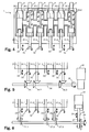
- FIG. 4 schematically shows a filling device according to the invention with six outlets 9 and six associated ejection cylinders 23.1, 23.2, 23.3, 23.4, 23.5, 23.6.
- the ejection cylinders 23.1, 23.4 and 23.5 are exemplary with a piston 20.1, 20.2 and 20.3 and associated connecting rods 21.1, 21.2 and 21.3.
- the ejection cylinder 23.2, 23.3 and 23.6 are exemplary with a worm 30.1, 30.2 and 30.3 and associated shafts 31.1, 31.2 and 31.3 equipped.
- one or more of the outputs 9 can also be put out of operation. This happens, for example, by blocking the inserted ejection element so that it is the Ejection movement does not execute. But it is also possible, no Ausstosselement in the insert respective ejection cylinder and the filling opening or the ejection opening the exhaust cylinder with other, any means to close. in principle could instead of an ejection cylinder and another device, such as a modified ejection cylinder, which has no filling opening at all, used become.
- Figure 5 shows how the rotational movement of the shafts 31.1, 31.2 and 31.3 and thus also that of the screws 30.1, 30.2 and 30.3 is generated.
- a motor 33 displaces a drive shaft 34 in a direction indicated by the arrow 35 rotational movement. This is going through one gear transmission 36.1, 36.2, 36.3, for example, two perpendicular to each other standing bevel gears, transmitted to the shafts 31.1, 31.2 and 31.3.
- FIGS. 6 and 7 show how the forward and backward movement of the connecting rods 21.1, 21.2 and 21.3 and thus also those of the pistons 20.1, 20.2 and 20.3 is generated.
- a pneumatic cylinder 24 a piston rod 25 in a forward and backward movement offset, which is indicated by the double arrows 26.
- These forward and Backward movement is transmitted via a lever 27 to a rotation axis 28, whose alternating rotational movement is indicated by the double arrow 29.
- Each another, attached to the axis of rotation 28 levers 27.1, 27.2 and 27.3 is the changing rotational movement of the rotation axis 28 finally back into a Forward and backward movement of the connecting rods 21.1, 21.2 and 21.3 converted.
- FIG. 7 shows further aspects.
- the lever 41 is at its lower end about a relative to the axis of rotation 28 fixed axis 42 rotatable stored.
- the lever 41 via a bolt 40 with a spindle 44th connected such that the upper end of the lever 41 hinund by turning the spindle 44 and can be moved.
- the pneumatic cylinder 24 with the Lever 41 can thus by rotating the spindle 44 relative to the rotation axis 28th be moved.
- the rotation of the spindle 44 and the displacement of the lever 41 and of the pneumatic cylinder 24 is indicated by the double arrows 45.
- Figure 8 shows the basic position of the lever 27.1, in which the piston 20.1 in is located at the rear reversal point 47 and the filling opening 6 releases for the most part.
- the piston moves forward in the direction of the outlet 9.
- the filling quantity 49 is now determined by the volume that the front end of the Piston 20.1 in the ejection cylinder 23.1 from the front edge 6.1 of the filling opening. 6 sweeps up to the front reversal point 46.
- Dashed are in Fig. 8 also the Positions of the piston 20.1, the connecting rod 21.1 and the lever 27.1 drawn when the piston 20.1 is in its front turning point 46. Because the piston 20.1 is in its basic position quite far right, is the swept volume and thus the filling amount 49 small.
- the pneumatic cylinder 24 is shifted to the right, wander the front turning point 46 and the rear turning point 47 together forward in the direction of the output 9. This will increase the volume that the piston from the front Edge 6.1 of the filling opening 6 sweeps to the front reversal point 46, and so that the capacity 49, increased. On the other hand, it remains the stroke of the piston 20.1, ie the distance between the two reversal points 46 and 47, essentially constant.
- the lever 27 is a stopper 50 and a switch 51st stationary with respect to the ejection cylinder 23.1, for example, on the frame of Filling device, attached. That in the illustration in Fig. 10 are in contrast to Representation in Fig. 8 of the stopper 50 and the switch 51 in operation.
- the pneumatic cylinder 24 is promptly so controlled that the piston rod 25 and thus also the piston 20.1 again move forward. Ie.
- the piston 20.1 in the ejection cylinder 23.1 can its backward movement not complete, but changes regardless of the position of the front reversal point prematurely back to forward movement.
- the positions of the stop 50 and the switch 51 are now selected such that in the Backward movement of the piston 20.1 of the stop 50 triggers the switch 51, as soon as the piston 20.1 the desired rear reversal point 47, for example, approximately in the center of the filling opening 6 is reached.
- stop 50 and switch 51 can also reversed or both the stopper 50 and the switch 51 in other places be positioned.
- the attack could be fixed in relation to the Output cylinder 23.1 or at any other location such as the connecting rod 21.1, be attached to the lever 27.1 or on the axis 28, wherein the switch so must be positioned so that it is actuated by the stop 50 at the right moment can.
- the invention allows the same in a single Filling the filling both by means of pistons and by means of screws on the dough applied. At a certain output can therefore be temporally as desired be filled one behind the other with a piston or a screw. And at several Outputs it is therefore possible, if necessary, one or more outputs with a piston and at the same time one or more outputs with a screw to operate.
Landscapes
- Life Sciences & Earth Sciences (AREA)
- Engineering & Computer Science (AREA)
- Food Science & Technology (AREA)
- Manufacturing And Processing Devices For Dough (AREA)
- Confectionery (AREA)
Abstract
Description
- Fig. 1
- Eine schematische Darstellung einer erfindungsgemässen Füllvorrichtung in einer Seitenansicht;
- Fig. 2
- eine schematische Darstellung eines Ausstosszylinders mit einem Kolben als Ausstosselement;
- Fig. 3
- eine schematische Darstellung eines Ausstosszylinders mit einer Schnecke als Ausstosselement;
- Fig. 4
- eine schematische Darstellung der geöffneten Füllvorrichtung aus Fig. 1 von oben;
- Fig. 5
- eine schematische Darstellung des Antriebs der Schnecken zum Ausstossen der Füllung mittels einer Rotationsbewegung von oben;
- Fig. 6
- eine schematische Darstellung des Antriebs der Kolben zum Ausstossen der Füllung mittels einer Vorwärts- und Rückwärtsbewegung von oben;
- Fig. 7
- eine schematische Darstellung des Antriebs aus Fig. 6 von der Seite,
- Fig. 8
- eine schematische Darstellung der Bewegung des Kolbens aus Fig. 6,
- Fig. 9
- eine schematische Darstellung der Verschiebung des vorderen und hinteren Umkehrpunktes sowie
- Fig. 10
- eine schematische Darstellung der Verschiebung nur des vorderen Umkehrpunktes.
Claims (15)
- Vorrichtung (1) mit zumindest einem Ausgang (9) zum Aufbringen einer Füllung auf eine teigartige Lebensmittelmasse, insbesondere einen Teig, sowie je einem Ausstosszylinder (23.1-23.6) und einem Ausstosselement (20.1-20.3, 30.1-30.3) für den zumindest einen Ausgang, wobei die Füllung mit dem Ausstosselement aus dem Ausstosszylinder ausstoss- und durch den zumindest einen Ausgang auf die Lebensmittelmasse aufbringbar ist, dadurch gekennzeichnet, dass das Ausstosselement des zumindest einen Ausgangs einen Kolben (20.1-20.3) zum Ausstossen der Füllung durch eine Vorwärts- und Rückwärtsbewegung (22) des Kolbens im Ausstosszylinder oder eine Schnecke (30.1-30.3) zum Ausstossen der Füllung durch eine Rotationsbewegung (32) der Schnecke umfasst, wobei ein Ausstosselement mit einem Kolben durch ein Ausstosselement mit einer Schnecke und umgekehrt auswechselbar ist.
- Vorrichtung nach Anspruch 1, dadurch gekennzeichnet, dass sie wenigstens einen Antrieb (8) zur Erzeugung einer Antriebsbewegung (35, 26) und je zumindest ein Getriebe (36.1-36.3, 27, 27.1-27.3) pro Ausgang zur Umwandlung der Antriebsbewegung in die Vorwärts- und Rückwärtsbewegung eines Kolbens bzw. in die Rotationsbewegung einer Schnecke umfasst.
- Vorrichtung nach Anspruch 2, dadurch gekennzeichnet, dass sie einen pneumatischen Antrieb (24) zum Erzeugen der Vorwärts- und Rückwärtsbewegung eines Kolbens und einen motorischen Antrieb (33) zum Erzeugen der Rotationsbewegung einer Schnecke umfasst.
- Vorrichtung nach einem der Ansprüche 1 bis 3, dadurch gekennzeichnet, dass eine Winkelgeschwindigkeit der Rotationsbewegung einer Schnecke und/oder eine Form der Schnecke variierbar ist.
- Vorrichtung nach einem der Ansprüche 1 bis 4, dadurch gekennzeichnet, dass sie derart ausgebildet ist, dass ein Kolben (20.1) in dem Ausstosszylinder (23.1) in einem vorderen Umkehrpunkt von der Vorwärtsbewegung in die Rückwärtsbewegung und in einem hinteren Umkehrpunkt von der Rückwärtsbewegung in die Vorwärtsbewegung übergeht, wobei der Ausstosszylinder bei der Rückwärtsbewegung des Kolbens durch eine Befüllungsöffnung (6) mit der Füllung befüllbar und die Füllung bei der Vorwärtsbewegung des Kolbens durch den Ausstosszylinder ausstossbar ist, und dass eine Frequenz der Vorwärts- und Rückwärtsbewegung des Kolbens und/oder eine Position des vorderen und gleichzeitig des hinteren Umkehrpunktes relativ zur Befüllungsöffnung variierbar ist.
- Vorrichtung nach Anspruch 5, dadurch gekennzeichnet, dass eine Position des hinteren Umkehrpunktes und/oder eine Position des vorderen Umkehrpunktes unabhängig von der Position des jeweils anderen Umkehrpunktes einstellbar ist.
- Vorrichtung nach einem der Ansprüche 1 bis 6, dadurch gekennzeichnet, dass ein Querschnitt des Ausstosszylinders variierbar ist.
- Vorrichtung nach einem der Ansprüche 1 bis 7, dadurch gekennzeichnet, dass sie einen Vorratsbehälter (2) für die Füllung sowie eine Transportvorrichtung (12) zum Transportieren der Lebensmittelmasse (11) umfasst, wobei die Füllung aus dem Vorratsbehälter, insbesondere mittels einer Einzugsvorrichtung (3), in den Ausstosszylinder des zumindest einen Ausgangs (9) beförderbar ist und die Lebensmittelmasse mit der Transportvorrichtung an dem zumindest einen Ausgang vorbei, insbesondere unter dem zumindest einen Ausgang hindurch, transportierbar ist.
- Vorrichtung nach einem der Ansprüche 1 bis 8, dadurch gekennzeichnet, dass sie wenigstens zwei und höchstens zwanzig Ausgänge und je einen Ausstosszylinder und ein Ausstosselement pro Ausgang umfasst.
- Vorrichtung nach einem der Ansprüche 1 bis 9, dadurch gekennzeichnet, dass ein Ausstosszylinder (23.1-23.6) zusammen mit dem entsprechenden Ausstosselement (7) derart als Modul ausgebildet ist, dass das Modul mit dem Ausstosselement durch ein entsprechendes Modul mit einem anderen Ausstosselement auswechselbar ist.
- Vorrichtung mit zumindest einem Ausgang (9) zum Aufbringen einer Füllung auf eine teigartige Lebensmittelmasse, insbesondere einen Teig, sowie je einem Ausstosszylinder (23.1) und einem Kolben (20.1) für den zumindest einen Ausgang, wobei die Vorrichtung derart ausgebildet ist, dass der Kolben in dem Ausstosszylinder jedes Ausgangs in einem vorderen Umkehrpunkt von einer Vorwärtsbewegung in eine Rückwärtsbewegung und in einem hinteren Umkehrpunkt von der Rückwärtsbewegung in die Vorwärtsbewegung übergeht, wobei der Ausstosszylinder bei der Rückwärtsbewegung des Kolbens durch eine Befüllungsöffnung (6) mit der Füllung befüllbar und die Füllung bei der Vorwärtsbewegung des Kolbens durch den Ausstosszylinder ausstossbar ist, dadurch gekennzeichnet, dass eine Position des hinteren Umkehrpunktes und/oder eine Position des vorderen Umkehrpunktes unabhängig von der Position des jeweils anderen Umkehrpunktes variierbar ist.
- Vorrichtung nach Anspruch 11, dadurch gekennzeichnet, dass die Position des vorderen Umkehrpunktes unter Beibehaltung der Position des hinteren Umkehrpunktes variierbar ist.
- Vorrichtung nach Anspruch 12, dadurch gekennzeichnet, dass sie einen Anschlag und einen Umschalter umfasst, wobei die Vorrichtung derart ausgebildet ist, dass eine Bewegungsrichtung des Kolbens umschaltbar ist durch eine Aktivierung des Umschalters mit dem Anschlag, wenn der Kolben bei seiner Rückwärtsbewegung eine bestimmte Position erreicht hat.
- Vorrichtung nach Anspruch 13, dadurch gekennzeichnet, dass der Umschalter bewegungsmässig mit dem Ausstosszylinder und der Anschlag bewegungsmässig mit dem Kolben gekoppelt ist.
- Vorrichtung nach Anspruch 14, dadurch gekennzeichnet, dass sie einen pneumatischen Antrieb mit einem Antriebszylinder, einem Antriebskolben und einer mit dem Antriebskolben verbundenen Antriebskolbenstange umfasst, wobei die Position des vorderen Umkehrpunktes mittels einer Verschiebung des Antriebszylinders in Bezug auf den Ausstosszylinder bzw. umgekehrt variierbar ist.
Priority Applications (1)
| Application Number | Priority Date | Filing Date | Title |
|---|---|---|---|
| EP20030405863 EP1520477B1 (de) | 2003-10-02 | 2003-12-04 | Füllvorrichtung für gefüllte Lebensmittel |
Applications Claiming Priority (3)
| Application Number | Priority Date | Filing Date | Title |
|---|---|---|---|
| EP03405711 | 2003-10-02 | ||
| EP03405711 | 2003-10-02 | ||
| EP20030405863 EP1520477B1 (de) | 2003-10-02 | 2003-12-04 | Füllvorrichtung für gefüllte Lebensmittel |
Publications (2)
| Publication Number | Publication Date |
|---|---|
| EP1520477A1 true EP1520477A1 (de) | 2005-04-06 |
| EP1520477B1 EP1520477B1 (de) | 2007-01-03 |
Family
ID=37681359
Family Applications (1)
| Application Number | Title | Priority Date | Filing Date |
|---|---|---|---|
| EP20030405863 Expired - Lifetime EP1520477B1 (de) | 2003-10-02 | 2003-12-04 | Füllvorrichtung für gefüllte Lebensmittel |
Country Status (3)
| Country | Link |
|---|---|
| EP (1) | EP1520477B1 (de) |
| DE (1) | DE50306201D1 (de) |
| ES (1) | ES2279086T3 (de) |
Families Citing this family (2)
| Publication number | Priority date | Publication date | Assignee | Title |
|---|---|---|---|---|
| NL2034873B1 (en) * | 2023-05-22 | 2024-12-03 | Radie Bv | Method and device for applying a preformed portioned malleable mass |
| EP4413862A1 (de) * | 2023-02-08 | 2024-08-14 | Radie B.V. | Verfahren und vorrichtung zum aufbringen einer vorgeformten portionierten verformbaren masse |
Citations (4)
| Publication number | Priority date | Publication date | Assignee | Title |
|---|---|---|---|---|
| EP0273762A2 (de) * | 1986-12-26 | 1988-07-06 | Rheon Automatic Machinery Co. Ltd. | Vorrichtung zur mengenmässigen Dosierung von Nahrungsmitteln |
| DE8715463U1 (de) * | 1987-11-21 | 1989-03-16 | Heinrich Döpke Maschinenfabrik, 2980 Norden | Teigbehälter-Füllautomat |
| US5517904A (en) * | 1994-02-14 | 1996-05-21 | The Pillsbury Company | Food product depositor |
| WO2002028190A1 (fr) * | 2000-10-03 | 2002-04-11 | Jacques Barde | Procede et machine pour garnir des sandwichs |
-
2003
- 2003-12-04 EP EP20030405863 patent/EP1520477B1/de not_active Expired - Lifetime
- 2003-12-04 DE DE50306201T patent/DE50306201D1/de not_active Expired - Lifetime
- 2003-12-04 ES ES03405863T patent/ES2279086T3/es not_active Expired - Lifetime
Patent Citations (4)
| Publication number | Priority date | Publication date | Assignee | Title |
|---|---|---|---|---|
| EP0273762A2 (de) * | 1986-12-26 | 1988-07-06 | Rheon Automatic Machinery Co. Ltd. | Vorrichtung zur mengenmässigen Dosierung von Nahrungsmitteln |
| DE8715463U1 (de) * | 1987-11-21 | 1989-03-16 | Heinrich Döpke Maschinenfabrik, 2980 Norden | Teigbehälter-Füllautomat |
| US5517904A (en) * | 1994-02-14 | 1996-05-21 | The Pillsbury Company | Food product depositor |
| WO2002028190A1 (fr) * | 2000-10-03 | 2002-04-11 | Jacques Barde | Procede et machine pour garnir des sandwichs |
Also Published As
| Publication number | Publication date |
|---|---|
| ES2279086T3 (es) | 2007-08-16 |
| DE50306201D1 (de) | 2007-02-15 |
| EP1520477B1 (de) | 2007-01-03 |
Similar Documents
| Publication | Publication Date | Title |
|---|---|---|
| DE1604331C2 (de) | Vorrichtung zum Zuteilen und kontrollierten Absetzen genau dosierter Mengen eines plastifizierten Kunststoffes | |
| DE2303436A1 (de) | Vorrichtung zum formen von nahrungsmittelportionen aus teigiger masse | |
| DE3789375T2 (de) | Vorrichtung zur mengenmässigen Dosierung von Nahrungsmitteln. | |
| DD249847A5 (de) | Vorrichtung zum quantitativen extrudieren von lebensmitteln | |
| EP0467886B1 (de) | Vorrichtung zum portionieren von teig | |
| DE2014693A1 (de) | Misch- und Kneteinrichtung | |
| DE1812291B2 (de) | Vorrichtung zum bilden weitgehend gewichtsgleicher tabakportionen | |
| DE3786772T2 (de) | Vorrichtung zur Dosierung einer gleichmässigen Menge von losen Nahrungsmitteln. | |
| DE69114062T2 (de) | Dosiervorrichtung für körnige oder pulverförmige Produkte und Rohkautschuk-Mischungsverfahren unter deren Verwendung. | |
| EP0585403B1 (de) | Maschine zum behandeln von teig | |
| DE102008055813B3 (de) | Vorrichtung und Verfahren zum Dosieren von Süßwarenmassen | |
| EP1520477B1 (de) | Füllvorrichtung für gefüllte Lebensmittel | |
| DE69317387T2 (de) | Dosierverfahren und -vorrichtung | |
| DE3630077C2 (de) | ||
| DE2556168C2 (de) | Ballenpresse zum Pressen von Altmaterial | |
| DE2461892A1 (de) | Kontinuierlich arbeitende maschine zum herstellen von gleichen teigteilchen | |
| DE3247621C2 (de) | Vorrichtung zum gleichmäßigen Portionieren von Teigteilen für Semmeln oder Kleinbrote | |
| DE3617413A1 (de) | Verfahren und vorrichtung zum herstellen gefuellter massen | |
| DE2315977A1 (de) | Vorrichtung zum bilden von teigportionen | |
| DE1432969A1 (de) | Vorrichtung zum Teilen von Teig od.dgl. | |
| DE3011863A1 (de) | Vorrichtung zum portionieren von teig fuer broetchen oder kleinbrote | |
| AT405007B (de) | Flügelzellenpumpe zum portionieren einer pastösen und kompressiblen masse sowie verfahren zu deren betrieb | |
| DE2352229A1 (de) | Fuellmaschine zum abfuellen plastisch verformbarer fuellmassen wie wurstbraet | |
| DE2201521C2 (de) | Formmaschine zum Herstellen von eine wählbare Anzahl von Schichten aufweisenden Produkten aus formbarem Material, insbesondere von Teigprodukten | |
| DE1132464B (de) | Vorrichtung zum Einfuehren von Wurstmasse oder aehnlichem Gut in schlauchfoermige Gebilde, z. B. in Daerme |
Legal Events
| Date | Code | Title | Description |
|---|---|---|---|
| PUAI | Public reference made under article 153(3) epc to a published international application that has entered the european phase |
Free format text: ORIGINAL CODE: 0009012 |
|
| AK | Designated contracting states |
Kind code of ref document: A1 Designated state(s): AT BE BG CH CY CZ DE DK EE ES FI FR GB GR HU IE IT LI LU MC NL PT RO SE SI SK TR |
|
| AX | Request for extension of the european patent |
Extension state: AL LT LV MK |
|
| 17P | Request for examination filed |
Effective date: 20050811 |
|
| AKX | Designation fees paid |
Designated state(s): CH DE ES FI IT LI NL |
|
| GRAP | Despatch of communication of intention to grant a patent |
Free format text: ORIGINAL CODE: EPIDOSNIGR1 |
|
| GRAS | Grant fee paid |
Free format text: ORIGINAL CODE: EPIDOSNIGR3 |
|
| GRAA | (expected) grant |
Free format text: ORIGINAL CODE: 0009210 |
|
| AK | Designated contracting states |
Kind code of ref document: B1 Designated state(s): CH DE ES FI IT LI NL |
|
| REF | Corresponds to: |
Ref document number: 50306201 Country of ref document: DE Date of ref document: 20070215 Kind code of ref document: P |
|
| REG | Reference to a national code |
Ref country code: ES Ref legal event code: FG2A Ref document number: 2279086 Country of ref document: ES Kind code of ref document: T3 |
|
| PLBE | No opposition filed within time limit |
Free format text: ORIGINAL CODE: 0009261 |
|
| STAA | Information on the status of an ep patent application or granted ep patent |
Free format text: STATUS: NO OPPOSITION FILED WITHIN TIME LIMIT |
|
| 26N | No opposition filed |
Effective date: 20071005 |
|
| PG25 | Lapsed in a contracting state [announced via postgrant information from national office to epo] |
Ref country code: IT Free format text: LAPSE BECAUSE OF NON-PAYMENT OF DUE FEES Effective date: 20071204 |
|
| PGRI | Patent reinstated in contracting state [announced from national office to epo] |
Ref country code: IT Effective date: 20110616 |
|
| REG | Reference to a national code |
Ref country code: CH Ref legal event code: PCAR Free format text: NEW ADDRESS: EIGERSTRASSE 2 POSTFACH, 3000 BERN 14 (CH) |
|
| PGFP | Annual fee paid to national office [announced via postgrant information from national office to epo] |
Ref country code: FI Payment date: 20191220 Year of fee payment: 17 Ref country code: NL Payment date: 20191224 Year of fee payment: 17 |
|
| PGFP | Annual fee paid to national office [announced via postgrant information from national office to epo] |
Ref country code: CH Payment date: 20191218 Year of fee payment: 17 |
|
| PGFP | Annual fee paid to national office [announced via postgrant information from national office to epo] |
Ref country code: ES Payment date: 20200103 Year of fee payment: 17 Ref country code: IT Payment date: 20191220 Year of fee payment: 17 Ref country code: DE Payment date: 20200124 Year of fee payment: 17 |
|
| REG | Reference to a national code |
Ref country code: CH Ref legal event code: PFA Owner name: SEEWER AG, CH Free format text: FORMER OWNER: SEEWER AG, CH |
|
| REG | Reference to a national code |
Ref country code: DE Ref legal event code: R119 Ref document number: 50306201 Country of ref document: DE |
|
| REG | Reference to a national code |
Ref country code: FI Ref legal event code: MAE |
|
| PG25 | Lapsed in a contracting state [announced via postgrant information from national office to epo] |
Ref country code: FI Free format text: LAPSE BECAUSE OF NON-PAYMENT OF DUE FEES Effective date: 20201204 |
|
| REG | Reference to a national code |
Ref country code: CH Ref legal event code: PL |
|
| REG | Reference to a national code |
Ref country code: NL Ref legal event code: MM Effective date: 20210101 |
|
| PG25 | Lapsed in a contracting state [announced via postgrant information from national office to epo] |
Ref country code: NL Free format text: LAPSE BECAUSE OF NON-PAYMENT OF DUE FEES Effective date: 20210101 |
|
| PG25 | Lapsed in a contracting state [announced via postgrant information from national office to epo] |
Ref country code: IT Free format text: LAPSE BECAUSE OF NON-PAYMENT OF DUE FEES Effective date: 20201204 |
|
| PG25 | Lapsed in a contracting state [announced via postgrant information from national office to epo] |
Ref country code: LI Free format text: LAPSE BECAUSE OF NON-PAYMENT OF DUE FEES Effective date: 20201231 Ref country code: DE Free format text: LAPSE BECAUSE OF NON-PAYMENT OF DUE FEES Effective date: 20210701 Ref country code: CH Free format text: LAPSE BECAUSE OF NON-PAYMENT OF DUE FEES Effective date: 20201231 |
|
| REG | Reference to a national code |
Ref country code: ES Ref legal event code: FD2A Effective date: 20220207 |
|
| PG25 | Lapsed in a contracting state [announced via postgrant information from national office to epo] |
Ref country code: ES Free format text: LAPSE BECAUSE OF NON-PAYMENT OF DUE FEES Effective date: 20201205 |