EP1520504A1 - Suceur d'aspirateur - Google Patents
Suceur d'aspirateur Download PDFInfo
- Publication number
- EP1520504A1 EP1520504A1 EP04356153A EP04356153A EP1520504A1 EP 1520504 A1 EP1520504 A1 EP 1520504A1 EP 04356153 A EP04356153 A EP 04356153A EP 04356153 A EP04356153 A EP 04356153A EP 1520504 A1 EP1520504 A1 EP 1520504A1
- Authority
- EP
- European Patent Office
- Prior art keywords
- nozzle
- sole
- brushes
- suction
- opening
- Prior art date
- Legal status (The legal status is an assumption and is not a legal conclusion. Google has not performed a legal analysis and makes no representation as to the accuracy of the status listed.)
- Granted
Links
- 230000033001 locomotion Effects 0.000 claims description 21
- 230000007246 mechanism Effects 0.000 claims description 8
- 230000005540 biological transmission Effects 0.000 claims description 3
- 238000004140 cleaning Methods 0.000 claims description 3
- 239000012780 transparent material Substances 0.000 claims description 2
- 239000000428 dust Substances 0.000 abstract description 5
- 239000002699 waste material Substances 0.000 description 8
- 239000002689 soil Substances 0.000 description 5
- 238000012800 visualization Methods 0.000 description 5
- 238000006073 displacement reaction Methods 0.000 description 4
- 230000006872 improvement Effects 0.000 description 3
- 241000252254 Catostomidae Species 0.000 description 2
- 230000009471 action Effects 0.000 description 2
- 230000000694 effects Effects 0.000 description 2
- 239000004744 fabric Substances 0.000 description 2
- 238000005304 joining Methods 0.000 description 2
- 238000005273 aeration Methods 0.000 description 1
- 230000001680 brushing effect Effects 0.000 description 1
- 239000000470 constituent Substances 0.000 description 1
- 238000010276 construction Methods 0.000 description 1
- 230000003247 decreasing effect Effects 0.000 description 1
- 230000007613 environmental effect Effects 0.000 description 1
- 239000000835 fiber Substances 0.000 description 1
- 238000002955 isolation Methods 0.000 description 1
- 238000004519 manufacturing process Methods 0.000 description 1
- 239000000463 material Substances 0.000 description 1
- 238000000034 method Methods 0.000 description 1
- 238000000465 moulding Methods 0.000 description 1
- 210000002445 nipple Anatomy 0.000 description 1
- 210000000056 organ Anatomy 0.000 description 1
- 238000003825 pressing Methods 0.000 description 1
- 230000008569 process Effects 0.000 description 1
- 230000001737 promoting effect Effects 0.000 description 1
- 238000007790 scraping Methods 0.000 description 1
- 239000002937 thermal insulation foam Substances 0.000 description 1
- 230000009466 transformation Effects 0.000 description 1
- 238000009423 ventilation Methods 0.000 description 1
Images


Classifications
-
- A—HUMAN NECESSITIES
- A47—FURNITURE; DOMESTIC ARTICLES OR APPLIANCES; COFFEE MILLS; SPICE MILLS; SUCTION CLEANERS IN GENERAL
- A47L—DOMESTIC WASHING OR CLEANING; SUCTION CLEANERS IN GENERAL
- A47L9/00—Details or accessories of suction cleaners, e.g. mechanical means for controlling the suction or for effecting pulsating action; Storing devices specially adapted to suction cleaners or parts thereof; Carrying-vehicles specially adapted for suction cleaners
- A47L9/02—Nozzles
- A47L9/06—Nozzles with fixed, e.g. adjustably fixed brushes or the like
- A47L9/0633—Nozzles with fixed, e.g. adjustably fixed brushes or the like with retractable brushes, combs, lips or pads
- A47L9/064—Nozzles with fixed, e.g. adjustably fixed brushes or the like with retractable brushes, combs, lips or pads actuating means therefor
- A47L9/0653—Nozzles with fixed, e.g. adjustably fixed brushes or the like with retractable brushes, combs, lips or pads actuating means therefor with mechanical actuation, e.g. using a lever
-
- A—HUMAN NECESSITIES
- A47—FURNITURE; DOMESTIC ARTICLES OR APPLIANCES; COFFEE MILLS; SPICE MILLS; SUCTION CLEANERS IN GENERAL
- A47L—DOMESTIC WASHING OR CLEANING; SUCTION CLEANERS IN GENERAL
- A47L9/00—Details or accessories of suction cleaners, e.g. mechanical means for controlling the suction or for effecting pulsating action; Storing devices specially adapted to suction cleaners or parts thereof; Carrying-vehicles specially adapted for suction cleaners
- A47L9/02—Nozzles
- A47L9/06—Nozzles with fixed, e.g. adjustably fixed brushes or the like
Definitions
- the present invention relates to a dust suction nozzle, and in particular, an improvement in the efficiency of waste collection.
- the vacuum suckers are the collection organs of waste contaminating the surface to be cleaned. They are therefore the object of many improvements aimed in particular at improving such collection.
- a nozzle vacuum cleaner provided with brushes and having air inlets at the level of suction nozzle, these air intakes being effective only when the brushes have returned.
- the brush outlet mechanism comprises a pivoting lever which, in its rotation, causes valves which allow or no to make the airflow connection between the air inlets at the hood and the tubing connecting the nozzle to the body of the vacuum cleaner.
- Such an air inlet allows to automatically create an air leak at the nozzle cover, thus decreasing locally the suction power at the nozzle, thus facilitating his movement.
- the present invention aims at improving the principle which has just been explained presenting an improved performance nozzle for a plurality of soils.
- the vacuum nozzle open towards the surface to be cleaned by at least one suction channel formed in the sole of the nozzle, said nozzle comprising at least one retractable brush, arranged in a housing and sliding up through an obviously realized in the soleplate, said brush being able to occupy two positions: an extended position where it is prominent relative to the sole of the squeegee and a position retracted where it is slightly set back from said sole, characterized in that that, in the extended position, the housing of the brush makes a tight contact to the air with the sole, while in the retracted position, at least one air passage is formed between the recess of the sole and the upper part of the nozzle, said upper portion having an air inlet opening to create a flow air entering the nozzle at this point and opening into the sole at level of the recess when the brush is in the retracted position.
- the two positions of the brush make it possible to obtain different contact depending on the soil to be treated and / or the actions envisaged. He is in interesting effect of being able to have a brush (s) to solicit the surface of the soil to be treated, for example the carpet, in order to extract the waste attached to the fibers.
- the air flows entering the nozzle may be advantageous to modify the air flows entering the nozzle according to the position of the brush or brushes. Indeed, when the brushes are out, the air is sucked essentially through the brushes. When they are retracted, the squeegee rests by the sole on the ground and an outside air inlet from the upper part of the nozzle is injected into the soil through the passage areas of the brushes arranged in the sole.
- Such an air intake at this level facilitates in particular the movement of the nozzle on the floor, but also makes it possible to create aeration blades in defined locations, including the borders of the channels where usually located the brushes, where a majority of the dust is raised and driven in the nozzle, thus contributing to a more efficient collection of waste.
- the upper part of the nozzle is constituted by a hood, the air inlet opening is then made at said hood.
- the hood has a perforated part on which is reported a window of visualization made of a transparent material.
- a possible construction is then to make the opening at the junction between the window of visualization and the perforated portion of the hood by a space between these parts, thus avoiding creating a particular opening at the hood, this which, moreover, could have been badly perceived by the user.
- an improvement consists in creating a baffle at the opening, in order to reduce the transmission of noise to the outside through this opening.
- the nozzle is substantially triangular shape including two side edges forming the tip of the nozzle, said nozzle having two channels arranged on the along the two lateral edges forming the tip of the nozzle, and in that each suction channel is bordered by front brushes and rear brushes slidable in recesses in the sole, said brushes being located on either side of the channel extending substantially parallel to the latter.
- each suction channel By lining each suction channel with brushes, it is possible to improve the suction efficiency at each of the channels since these are somehow closed by said brushes. Moreover, two brushing operations of the soil to be treated immediately followed by a suction will occur regardless of the direction of movement of the nozzle, that either forward or backward.
- both positions of the brush or brushes are controlled by a mechanism operated by a pedal.
- the pedal is advantageously mounted in rotation on the sole of the squeegee, the rod being connected, on the one hand to the pedal by a portion parallel to the axis of rotation of the pedal, and secondly to trolleys by portions substantially perpendicular to the axis of rotation of the pedal, so that such a rotation of the pedal causes a displacement horizontal carts.
- the rockers and trolleys are symmetrical by relative to a median vertical plane at the nozzle, which makes it possible to distribute equitably the efforts on each sub-assembly formed by a carriage, a tipper, a front brush and a back brush.
- This symmetry guarantees a uniform movement of the different brushes.
- the brushes at the back of the channels meet at the junction of the two side channels in forming an inverted V.
- this rear brush extending sinuously from one edge to the other of the nozzle allows, when the brushes are out, a good stability the nozzle on the floor to be treated without the risk of tilting forward or backward the nozzle during his travels.
- the nozzle remains well flat on the floor to clean.
- each rocker comprises the points support of one of the front brushes and some of the support points of the rear brush.
- the front edge of the nozzle has at least one front port intended to provide suction in a substantially direction parallel to the surface to be cleaned, said front suction port being connected to one suction channels.
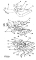
- the present invention relates to a vacuum nozzle 1.
- a vacuum nozzle has a connection tube 2 connecting to a vacuum cleaner body, no represented, in particular having a motor-fan capable of creating a air suction flow.
- the connecting tube 2 opens at the sole 11 of the nozzle in contact with the ground 4 to be cleaned, via connection 3.
- These ducts lead to the suction channels.
- These channels are usually configured according to the shape of the nozzle, to optimize suction efficiency. In the example presented where the nozzle is shaped triangular, the suction channels, as represented by the dashed lines 10, extend in part along the two edges 5, 6 forming the tip of the nozzle, as well as in said tip of the nozzle after joining in the part central of the nozzle.
- the angular zone forming the tip of the nozzle comprises a front orifice 7 intended to ensure suction in a direction substantially parallel to the surface to be cleaned.
- the nozzle has retractable brushes actuated by a pedal 8 pivoting.
- This pedal 8 is accessible at the hood 12 of the nozzle.
- the latter in this embodiment, essentially only presents functions aesthetic and environmental protection.
- the suction channels are closed, on the one hand by a internal structure made in part during the manufacture by molding of the sole, such as the parts of the suction channels extending along the edges and opening through the opening 7, but also by an upper part 14 which, according to the exemplary embodiment, is a viewing zone made of making transparent the triangular piece reported on the sole.
- this viewing area can cover a larger field that of the suction channel, in order to adjust the aim of the waste to be extracted from the ground.
- the cover 12 then has a simple opening 15 opposite the Exhibit 14, as shown in FIG.
- the viewing area has a magnifying effect, by having a convex shape.
- the waste under the zone of visualization are magnified, thus improving the visualization of the surface to clean.
- Figure 2 shows the nozzle seen from below.
- the sole 11 of nozzle has several suction channels: a channel 19 substantially parallel to the edge 6 of the nozzle, a channel 20 substantially parallel to the edge 5 of the nozzle. These channels meet in the central region 21 of the nozzle.
- the channels 19 and 20 have front openings, that is to say in the vertical flanges of the sole, respectively 36 and 35, allowing a lateral suction substantially parallel to the surface to be cleaned.
- the triangular shape is completed, at the rear of the nozzle, by a part full 40 having two locations 42 means promoting the displacement of the nozzle, which may be either PTFE-type pads or wheels, such as the wheels 43 visible in FIG. 9.
- the nozzle further comprises a blade 23 extending in the region 21, the edge 5 of the nozzle at the edge 6, thus defining a channel before 18 and a rear channel 22, the front channel 18 opening at the tip of the nozzle by the front opening 7.
- This blade 23 has a zone 24 where is disposed a pull-out fabric as it is known per se.
- This blade 23 connects the edge 5 to the edge 6 as a bridge, leaving a space between the face opposite the zone 24 and the upper part 14. This blade is preferably parallel to the rear edge 9 of the nozzle.
- a second zone 124 carrying a pull-out fabric may be provided on a border of the channel 22, symmetrically to the zone 24 carrying the pull-son.
- the channels 19 and 20 each have scraping blades 46 and 45 extending respectively from the edge 6 and the edge 5 towards the other edge in the suction channel.
- these blades are fixed and issuing from the bottom plate of the nozzle while extending substantially parallel to the rear edge 9 for a distance close to half of the width of the canal.
- these blades are not or are little protruding from the bottom plate of the nozzle.
- the nozzle comprises brushes 55, 56, 57, said brushes being retractable through the sole.
- the brush 55 is disposed between the suction channel 20 and the edge 5, while the brush 56 is disposed between the suction channel 19 and the edge 6.
- the channels 19 and 20 are joining in the front part of the nozzle forming an inverted V, the back brush 57 follows this shape along the border defined by the two channels and their meet.
- the rear brush presents including a notch 157 in the middle of the brush, ie in the bowl form of said brush, to facilitate the suction of waste that can be housed in this form of the brush at the time of movement towards the back of the nozzle.
- Figures 3, 4 and 5 represent, in isolation, the brushes and the output control mechanism of said brushes.
- a remarkable fact of device is, besides the arrangement of the pedal, its perfect symmetry with respect at a vertical median plane and perpendicular to the nozzle.
- the pedal 8 has a lateral pin 81 intended for its connection with the sole of the nozzle, via a vertical piece 82, visible figure 9 and having a hole in which said stud is housed.
- the nipple thus housed in the piece 82 constitutes a pivot axis of the pedal. This last also has a hollow extension 83.
- the pedal 8 is connected to a rigid rod 28 for transmitting movement, this rod being fixed to the pedal in the extension of the axis of rotation of the pedal, ie in the extension of the pin 81, as it is clearly visible in FIG. 4.
- This rod comprises several elbows constituting a specific form whose particularity is to remain flat in constituting in particular a horizontal part 280 which is the connecting part with the pedal, and two substantially vertical portions 282. These are located at each end of the stem and are each connected with a 85, 86.
- the vertical portion 282 located under the pedal 8 passes into the hollow portion of the extension 83 of the pedal which thus constitutes a guide of the rod and ensures the transmission of the force to the rod.
- the rod 28 is also supported by two vertical supports 128 from of the sole.
- the trolleys 85, 86 are two identical L-shaped pieces in having a rather long horizontal part directed towards the front of the nozzle and a shorter vertical part directed downwards. These trolleys are subject between the sole of the squeegee and the hood so that it can move only horizontally, forward or backward of the nozzle. Two arches 194, visible figure 10, from the sole and through which are mounted the trolleys 85, 86, in particular make it possible to prohibit any vertical movement said carts.
- Each carriage 85, 86 has, at the front end of their part horizontal, a bevelled shape, respectively 185, 186.
- These portions Bevels are cam surfaces that can interact with parts 125, 126 beveled identically in independent parts 75, 76 in correspondence called rockers, during the horizontal displacement said carts.
- the canted portions 125, 126 open, in part higher, on a substantially horizontal flat portion, respectively 25, 26.
- each carriage 85, 86 is likely to interact with respectively the rocker 75 and the rocker 76.
- the rockers are substantially planar pieces which are mounted in the squeegee by presenting a degree of freedom in a vertical direction, while being maintained in their horizontal clearance essentially by the sole of the squeegee, for example with slide pins 192 coming from the sole and on which can slide the rockers through openings 175, 176 in 192.
- each pawn or some of them may be provided with gaudrons or small vertical bulges to facilitate translation vertical rockers.
- the sole will also be equipped with gaudrons under each carriage for maintaining the carriages in the output position of the brushes to prevent accidental triggering of the mechanism.
- a spring 165, 166 is mounted between each tipper 75, 76 and the sole of the nozzle.
- Each rocker comprises housings 65, 66 for the brushes 55, 56, each brush being held at the housing, essentially by resilient clamps of the type clips 95, 96.
- the sole comprises openings for the passage of the brushes.
- an opening 600 allows the vertical movement of the brush 56 to allow the latter to emerge from the sole.
- This opening is delimited by an outline advantageously castellated 602 making it possible to produce a watertight stop housing 66 brushes on the sole when the brush is out.
- a space is provided at the passages 600 of brushes thus allowing an aeraulic connection between the inside of the nozzle and the space under the sole.
- a ventilation link is also formed between the inside of the nozzle and the outside at the hood 12 of the nozzle.
- FIG. 13 which is a sectional view along A-A of FIG. 12, present the air inlet 134 at the connection between the nozzle and the tube of connection 2. This air inlet is simply obtained by sufficient space at the opening 13 of the hood delimited by the contour 130, between the connecting ducts 3 and the hood 12.
- a substantially vertical wall 132 is disposed at proximity of the air inlet 134.
- This wall cooperates with a wall substantially vertical 195 closing the suction channel, said wall being from the sole, to create a baffle for the incoming air, as it is 13.
- Such a baffle makes it possible to reduce the noise associated with the passage of the air.
- the substantially vertical portions 282 also pivot, causing a forward displacement of the carriages 85, 86 linked to the ends 282 of said rod.
- This advance of the carriages entails the cooperation of the parties beveled trolleys with those of the rockers. Given the impossibility of vertical movement of the trolleys and the impossibility of horizontal movement of the rockers, the latter, under the movement towards the front of the carriages, undergo a downward vertical movement against the restoring force of the springs 165, 166, the play of the slopes sliding the tippers 75, 76 under the carriages 85, 86, the latter being in support respective on planar portions 25, 26.
- the brushes in the out position delimit a height guard predetermined between the ground and the sole defining the passage section lower air inlet device.
- the dust released by the brushes are removed by the horizontal horizontal air flows at the periphery of the nozzle then vertical up in the channels.
- the air flow is then conducted to create airflow blades in strategic locations, namely along the canals where all dust is raised.
- the air inlet under the sole of the nozzle allows also facilitate his movement.
- the air inlet can be made at the opening 80 for housing the pedal 8, or at the level of the viewing aperture 15, ...
Landscapes
- Engineering & Computer Science (AREA)
- Mechanical Engineering (AREA)
- Nozzles For Electric Vacuum Cleaners (AREA)
- Cleaning In General (AREA)
- Jet Pumps And Other Pumps (AREA)
- Manipulator (AREA)
- Sheets, Magazines, And Separation Thereof (AREA)
- Liquid Crystal (AREA)
Abstract
Description
- deux basculeurs portant les brosses et mobiles verticalement par rapport à la semelle contre la force de rappel de deux ressorts,
- deux chariots mobiles horizontalement et susceptibles d'interagir chacun avec l'un des basculeurs par l'intermédiaire d'une surface de came inclinée lors de ce mouvement horizontal,
- une tige de liaison liant la pédale de commande aux deux chariots.
- la figure 1 présente, dans une vue schématique de dessus, un suceur conforme à la présente invention,
- la figure 2 présente une vue de dessous d'un suceur selon l'invention,
- les figures 3 et 4 représentent, en perspective, respectivement une vue de dessus et de dessous de certaines parties constitutives d'un suceur selon l'invention,
- les figures 5 et 6 représentent, dans une vue en élévation latérale, respectivement une vue du suceur brosses sorties et une vue du suceur brosses rentrées, la semelle du suceur ayant été omise,
- les figures 7 et 8 présentent dans une vue de profil, respectivement une vue du suceur brosses sorties et une vue du suceur brosses rentrées,
- la figure 9 est une vue éclatée du suceur selon l'invention,
- la figure 10 est une vue en perspective avant de la semelle munie de la fenêtre de visualisation,
- la figure 11 est une vue du capot retourné avec certaines parties apparentes du suceur,
- la figure 12 est une vue de dessus du suceur,
- la figure 13 est une vue en coupe selon l'axe A-A de la figure 12.
Claims (12)
- Suceur (1) d'aspirateur ouvert vers la surface (4) à nettoyer par au moins un canal d'aspiration (19, 20) ménagé dans la semelle (11) du suceur (1), ledit suceur (1) comportant au moins une brosse (55, 56, 57) escamotable, agencée dans un logement (65, 66, 67) et montée en coulissement au travers d'un évidement (600) réalisé dans la semelle, ladite brosse (55, 56, 57) pouvant occuper deux positions : une position sortie où elle est proéminente par rapport à la semelle (11) du suceur (1) et une position rentrée où elle est légèrement en retrait de ladite semelle (11), caractérisé en ce que, en position sortie, le logement (65, 66, 67) de la brosse (55, 56, 57) réalise un contact étanche à l'air avec la semelle (11), alors qu'en position rentrée, au moins un passage d'air est ménagé entre l'évidement (600) de la semelle (11) et la partie supérieure du suceur, ladite partie supérieure comportant une ouverture (134) d'entrée d'air, afin de créer un flux d'air entrant dans le suceur à cet endroit et débouchant dans la semelle (11) au niveau de l'évidement (600) lorsque la brosse (55, 56, 57) est en position rentrée.
- Suceur (1) d'aspirateur selon la revendication précédente, caractérisé en ce que la partie supérieure du suceur (1) est constituée par un capot (12) et en ce que l'ouverture d'entrée d'air est réalisée au niveau dudit capot (12).
- Suceur (1) d'aspirateur selon la revendication précédente, caractérisé en ce que le capot (12) comporte une partie ajourée sur laquelle est rapportée une fenêtre de visualisation (14) réalisée en un matériau transparent, l'ouverture étant réalisée au niveau de la jonction entre la fenêtre de visualisation (14) et la partie ajourée du capot par un espace ménagé entre ces pièces.
- Suceur (1) d'aspirateur selon la revendication 1, caractérisé en ce que l'ouverture d'entrée d'air est réalisée dans le capot au niveau de l'ouverture (13) de logement des conduits de raccordement (3), par un espace ménagé entre ces pièces et le bord (130) délimitant l'ouverture (13).
- Suceur (1) d'aspirateur selon l'une des revendications 1 à 3, caractérisé en ce qu'une chicane est réalisée au niveau de l'ouverture afin de réduire la transmission du bruit vers l'extérieur par cette ouverture.
- Suceur (1) d'aspirateur selon l'une des revendications précédentes, caractérisé en ce qu'il est de forme sensiblement triangulaire en présentant notamment deux bords latéraux (5, 6) formant la pointe du suceur, ledit suceur comportant deux canaux (19, 20) agencés le long des deux bords latéraux (6, 5) formant la pointe du suceur, et en ce que chaque canal d'aspiration (19, 20) est bordé par des brosses avant (56, 55) et des brosses arrière (57) pouvant coulisser dans des évidements ménagés dans la semelle, lesdites brosses étant situées de part et d'autre du canal en s'étendant sensiblement parallèlement à ce dernier.
- Suceur (1) d'aspirateur selon l'une des revendications précédentes, caractérisé en ce que les deux positions de la brosse ou des brosses sont contrôlées par un mécanisme actionné par une pédale (8).
- Suceur (1) d'aspirateur selon la revendication précédente, caractérisé en ce que le mécanisme comporte :deux basculeurs (75, 76) portant les brosses (55, 56, 57) et mobiles verticalement par rapport à la semelle (11) contre la force de rappel de deux ressorts (165, 166),deux chariots (85, 86) mobiles horizontalement et susceptibles d'interagir chacun avec l'un des basculeurs (75, 76) par l'intermédiaire d'une surface de came inclinée (125, 126, 185, 186), lors de ce mouvement horizontal,une tige de liaison (28) liant la pédale de commande (8) aux deux chariots (85, 86).
- Suceur (1) d'aspirateur selon la revendication précédente, caractérisé en ce que la pédale (8) est montée en rotation sur la semelle (11) du suceur (1) et en ce que la tige (28) est liée, d'une part à la pédale (8) par une portion parallèle (280) à l'axe de rotation de la pédale, et d'autre part aux chariots (85, 86) par des portions (282) sensiblement perpendiculaires à l'axe de rotation de la pédale (8), de sorte qu'une telle rotation de la pédale (8) provoque un déplacement horizontal des chariots (85, 86).
- Suceur (1) d'aspirateur selon la revendication précédente, caractérisé en ce que les basculeurs (75, 76) et chariots (85, 86) sont symétriques par rapport à un plan vertical médian au suceur (1).
- Suceur (1) d'aspirateur selon la revendication précédente, caractérisé en ce que chaque basculeur (75, 76) comporte les points d'appui (95, 96) de l'une des brosses avant et une partie (97, 98) des points d'appui de la brosse arrière (57).
- Suceur (1) d'aspirateur selon l'une des revendications précédentes, caractérisé en ce que le rebord avant du suceur présente au moins un orifice frontal (7) destiné à assurer une aspiration dans une direction sensiblement parallèle à la surface (4) à nettoyer, ledit orifice frontal (7) d'aspiration étant relié à l'un des canaux (19, 20, 21) d'aspiration.
Applications Claiming Priority (2)
| Application Number | Priority Date | Filing Date | Title |
|---|---|---|---|
| FR0311477 | 2003-10-01 | ||
| FR0311477A FR2860415B1 (fr) | 2003-10-01 | 2003-10-01 | Suceur d'aspirateur |
Publications (2)
| Publication Number | Publication Date |
|---|---|
| EP1520504A1 true EP1520504A1 (fr) | 2005-04-06 |
| EP1520504B1 EP1520504B1 (fr) | 2008-03-12 |
Family
ID=34307303
Family Applications (1)
| Application Number | Title | Priority Date | Filing Date |
|---|---|---|---|
| EP04356153A Expired - Lifetime EP1520504B1 (fr) | 2003-10-01 | 2004-09-13 | Suceur d'aspirateur |
Country Status (5)
| Country | Link |
|---|---|
| EP (1) | EP1520504B1 (fr) |
| AT (1) | ATE388659T1 (fr) |
| DE (1) | DE602004012363T2 (fr) |
| ES (1) | ES2301955T3 (fr) |
| FR (1) | FR2860415B1 (fr) |
Cited By (3)
| Publication number | Priority date | Publication date | Assignee | Title |
|---|---|---|---|---|
| CN105982614A (zh) * | 2015-02-27 | 2016-10-05 | 苏州市海泉电器有限公司 | 用于吸尘器的地刷 |
| AT518179B1 (de) * | 2016-02-25 | 2017-08-15 | Erwin Ladinig | Vorrichtung zum Reinigen textiler Gegenstände |
| CN110217563A (zh) * | 2019-06-11 | 2019-09-10 | 湖南隋侯珠科技有限公司 | 一种二合一移液吸头排列机器人 |
Families Citing this family (1)
| Publication number | Priority date | Publication date | Assignee | Title |
|---|---|---|---|---|
| DE102014106003B4 (de) * | 2014-04-29 | 2020-01-23 | Wessel-Werk Gmbh | Staubsaugerdüse mit Schaltwelle und Betätigungselement sowie Verfahren zur Herstellung eines Betätigungselementes |
Citations (5)
| Publication number | Priority date | Publication date | Assignee | Title |
|---|---|---|---|---|
| GB1119876A (en) * | 1965-07-17 | 1968-07-17 | Siemens Elektrogeraete Gmbh | Improvements in or relating to vacuum cleaner nozzle |
| US3660864A (en) * | 1969-02-06 | 1972-05-09 | Electrolux Ab | Multi-purpose suction cleaner nozzle |
| GB1505783A (en) * | 1975-11-06 | 1978-03-30 | Electrolux Ltd | Vacuum cleaner nozzle assembly |
| DE19828873A1 (de) * | 1998-06-25 | 1999-12-30 | Bsh Bosch Siemens Hausgeraete | Staubsaugermundstück |
| US20020166193A1 (en) * | 1997-07-09 | 2002-11-14 | Kasper Gary A. | Upright extraction cleaning machine with unitary accessory hose duct |
-
2003
- 2003-10-01 FR FR0311477A patent/FR2860415B1/fr not_active Expired - Fee Related
-
2004
- 2004-09-13 EP EP04356153A patent/EP1520504B1/fr not_active Expired - Lifetime
- 2004-09-13 ES ES04356153T patent/ES2301955T3/es not_active Expired - Lifetime
- 2004-09-13 AT AT04356153T patent/ATE388659T1/de not_active IP Right Cessation
- 2004-09-13 DE DE602004012363T patent/DE602004012363T2/de not_active Expired - Lifetime
Patent Citations (5)
| Publication number | Priority date | Publication date | Assignee | Title |
|---|---|---|---|---|
| GB1119876A (en) * | 1965-07-17 | 1968-07-17 | Siemens Elektrogeraete Gmbh | Improvements in or relating to vacuum cleaner nozzle |
| US3660864A (en) * | 1969-02-06 | 1972-05-09 | Electrolux Ab | Multi-purpose suction cleaner nozzle |
| GB1505783A (en) * | 1975-11-06 | 1978-03-30 | Electrolux Ltd | Vacuum cleaner nozzle assembly |
| US20020166193A1 (en) * | 1997-07-09 | 2002-11-14 | Kasper Gary A. | Upright extraction cleaning machine with unitary accessory hose duct |
| DE19828873A1 (de) * | 1998-06-25 | 1999-12-30 | Bsh Bosch Siemens Hausgeraete | Staubsaugermundstück |
Cited By (6)
| Publication number | Priority date | Publication date | Assignee | Title |
|---|---|---|---|---|
| CN105982614A (zh) * | 2015-02-27 | 2016-10-05 | 苏州市海泉电器有限公司 | 用于吸尘器的地刷 |
| CN105982614B (zh) * | 2015-02-27 | 2018-09-25 | 苏州市海泉电器有限公司 | 用于吸尘器的地刷 |
| AT518179B1 (de) * | 2016-02-25 | 2017-08-15 | Erwin Ladinig | Vorrichtung zum Reinigen textiler Gegenstände |
| AT518179A4 (de) * | 2016-02-25 | 2017-08-15 | Erwin Ladinig | Vorrichtung zum Reinigen textiler Gegenstände |
| CN110217563A (zh) * | 2019-06-11 | 2019-09-10 | 湖南隋侯珠科技有限公司 | 一种二合一移液吸头排列机器人 |
| CN110217563B (zh) * | 2019-06-11 | 2024-04-19 | 湖南隋侯珠科技有限公司 | 一种二合一移液吸头排列机器人 |
Also Published As
| Publication number | Publication date |
|---|---|
| DE602004012363D1 (de) | 2008-04-24 |
| DE602004012363T2 (de) | 2009-03-12 |
| FR2860415B1 (fr) | 2006-05-19 |
| FR2860415A1 (fr) | 2005-04-08 |
| ES2301955T3 (es) | 2008-07-01 |
| ATE388659T1 (de) | 2008-03-15 |
| EP1520504B1 (fr) | 2008-03-12 |
Similar Documents
| Publication | Publication Date | Title |
|---|---|---|
| EP1173085B1 (fr) | Suceur d'aspirateur a lame de raclage | |
| EP1047328B1 (fr) | Suceur d'aspirateur | |
| WO2002085174A1 (fr) | Embout pour aspirateur | |
| FR2747907A1 (fr) | Aspirateur a bol a poussiere avec conversion de tuyau | |
| EP0951229A1 (fr) | Dispositif de connexion d'un sac a poussieres d'aspirateur | |
| EP1488726B1 (fr) | Suceur d'aspirateur | |
| FR3062562A1 (fr) | Tete de succion d’aspirateur a trois positions | |
| EP1520504B1 (fr) | Suceur d'aspirateur | |
| EP2201876B1 (fr) | Suceur d'aspirateur | |
| EP3360452B1 (fr) | Tête de succion d'aspirateur | |
| FR2773317A1 (fr) | Suceur d'aspirateur | |
| EP3530168A1 (fr) | Suceur d'aspirateur combinant une première et une deuxième tête d'aspiration reliées entre elles par un système d'articulation | |
| EP1488728B1 (fr) | Suceur d'aspirateur | |
| EP1532914A1 (fr) | Suceur d'aspirateur | |
| FR2774884A1 (fr) | Outil de nettoyage aspirant, suceur de sol en particulier | |
| EP0623304A1 (fr) | Suceur pour aspirateur de poussières | |
| EP1488727B1 (fr) | Suceur d'aspirateur | |
| EP1369074B1 (fr) | Suceur d'aspirateur à dispositif de raclage | |
| FR2525456A1 (fr) | Chariot de nettoyage par aspiration | |
| FR2601239A1 (fr) | Aspirateur plus particulierement adapte aux revetements de meme nature que tapis ou moquettes. | |
| WO1999035953A1 (fr) | Patins de glissement pour appareil electromenager | |
| FR3155696A1 (fr) | Robot de nettoyage autonome équipé d’un dispositif de nettoyage | |
| EP1407706A1 (fr) | Suceur d'aspirateur perfectionné | |
| FR3156298A1 (fr) | Robot de nettoyage autonome équipé de deux éléments de nettoyage latéraux fixes | |
| FR2860413A1 (fr) | Suceur d'aspirateur |
Legal Events
| Date | Code | Title | Description |
|---|---|---|---|
| PUAI | Public reference made under article 153(3) epc to a published international application that has entered the european phase |
Free format text: ORIGINAL CODE: 0009012 |
|
| AK | Designated contracting states |
Kind code of ref document: A1 Designated state(s): AT BE BG CH CY CZ DE DK EE ES FI FR GB GR HU IE IT LI LU MC NL PL PT RO SE SI SK TR |
|
| AX | Request for extension of the european patent |
Extension state: AL HR LT LV MK |
|
| 17P | Request for examination filed |
Effective date: 20050916 |
|
| AKX | Designation fees paid |
Designated state(s): AT BE BG CH CY CZ DE DK EE ES FI FR GB GR HU IE IT LI LU MC NL PL PT RO SE SI SK TR |
|
| REG | Reference to a national code |
Ref country code: HK Ref legal event code: DE Ref document number: 1076696 Country of ref document: HK |
|
| 17Q | First examination report despatched |
Effective date: 20070226 |
|
| GRAP | Despatch of communication of intention to grant a patent |
Free format text: ORIGINAL CODE: EPIDOSNIGR1 |
|
| GRAS | Grant fee paid |
Free format text: ORIGINAL CODE: EPIDOSNIGR3 |
|
| GRAA | (expected) grant |
Free format text: ORIGINAL CODE: 0009210 |
|
| AK | Designated contracting states |
Kind code of ref document: B1 Designated state(s): AT BE BG CH CY CZ DE DK EE ES FI FR GB GR HU IE IT LI LU MC NL PL PT RO SE SI SK TR |
|
| REG | Reference to a national code |
Ref country code: GB Ref legal event code: FG4D Free format text: NOT ENGLISH |
|
| REG | Reference to a national code |
Ref country code: CH Ref legal event code: EP |
|
| REG | Reference to a national code |
Ref country code: IE Ref legal event code: FG4D Free format text: LANGUAGE OF EP DOCUMENT: FRENCH |
|
| REF | Corresponds to: |
Ref document number: 602004012363 Country of ref document: DE Date of ref document: 20080424 Kind code of ref document: P |
|
| REG | Reference to a national code |
Ref country code: ES Ref legal event code: FG2A Ref document number: 2301955 Country of ref document: ES Kind code of ref document: T3 |
|
| PG25 | Lapsed in a contracting state [announced via postgrant information from national office to epo] |
Ref country code: FI Free format text: LAPSE BECAUSE OF FAILURE TO SUBMIT A TRANSLATION OF THE DESCRIPTION OR TO PAY THE FEE WITHIN THE PRESCRIBED TIME-LIMIT Effective date: 20080312 |
|
| PG25 | Lapsed in a contracting state [announced via postgrant information from national office to epo] |
Ref country code: AT Free format text: LAPSE BECAUSE OF FAILURE TO SUBMIT A TRANSLATION OF THE DESCRIPTION OR TO PAY THE FEE WITHIN THE PRESCRIBED TIME-LIMIT Effective date: 20080312 |
|
| NLV1 | Nl: lapsed or annulled due to failure to fulfill the requirements of art. 29p and 29m of the patents act | ||
| PG25 | Lapsed in a contracting state [announced via postgrant information from national office to epo] |
Ref country code: SI Free format text: LAPSE BECAUSE OF FAILURE TO SUBMIT A TRANSLATION OF THE DESCRIPTION OR TO PAY THE FEE WITHIN THE PRESCRIBED TIME-LIMIT Effective date: 20080312 Ref country code: PL Free format text: LAPSE BECAUSE OF FAILURE TO SUBMIT A TRANSLATION OF THE DESCRIPTION OR TO PAY THE FEE WITHIN THE PRESCRIBED TIME-LIMIT Effective date: 20080312 |
|
| PGFP | Annual fee paid to national office [announced via postgrant information from national office to epo] |
Ref country code: TR Payment date: 20080603 Year of fee payment: 5 |
|
| REG | Reference to a national code |
Ref country code: IE Ref legal event code: FD4D |
|
| PG25 | Lapsed in a contracting state [announced via postgrant information from national office to epo] |
Ref country code: SK Free format text: LAPSE BECAUSE OF FAILURE TO SUBMIT A TRANSLATION OF THE DESCRIPTION OR TO PAY THE FEE WITHIN THE PRESCRIBED TIME-LIMIT Effective date: 20080312 Ref country code: PT Free format text: LAPSE BECAUSE OF FAILURE TO SUBMIT A TRANSLATION OF THE DESCRIPTION OR TO PAY THE FEE WITHIN THE PRESCRIBED TIME-LIMIT Effective date: 20080818 Ref country code: SE Free format text: LAPSE BECAUSE OF FAILURE TO SUBMIT A TRANSLATION OF THE DESCRIPTION OR TO PAY THE FEE WITHIN THE PRESCRIBED TIME-LIMIT Effective date: 20080612 Ref country code: CZ Free format text: LAPSE BECAUSE OF FAILURE TO SUBMIT A TRANSLATION OF THE DESCRIPTION OR TO PAY THE FEE WITHIN THE PRESCRIBED TIME-LIMIT Effective date: 20080312 |
|
| PG25 | Lapsed in a contracting state [announced via postgrant information from national office to epo] |
Ref country code: NL Free format text: LAPSE BECAUSE OF FAILURE TO SUBMIT A TRANSLATION OF THE DESCRIPTION OR TO PAY THE FEE WITHIN THE PRESCRIBED TIME-LIMIT Effective date: 20080312 Ref country code: RO Free format text: LAPSE BECAUSE OF FAILURE TO SUBMIT A TRANSLATION OF THE DESCRIPTION OR TO PAY THE FEE WITHIN THE PRESCRIBED TIME-LIMIT Effective date: 20080312 |
|
| PLBE | No opposition filed within time limit |
Free format text: ORIGINAL CODE: 0009261 |
|
| STAA | Information on the status of an ep patent application or granted ep patent |
Free format text: STATUS: NO OPPOSITION FILED WITHIN TIME LIMIT |
|
| PG25 | Lapsed in a contracting state [announced via postgrant information from national office to epo] |
Ref country code: IE Free format text: LAPSE BECAUSE OF FAILURE TO SUBMIT A TRANSLATION OF THE DESCRIPTION OR TO PAY THE FEE WITHIN THE PRESCRIBED TIME-LIMIT Effective date: 20080312 Ref country code: DK Free format text: LAPSE BECAUSE OF FAILURE TO SUBMIT A TRANSLATION OF THE DESCRIPTION OR TO PAY THE FEE WITHIN THE PRESCRIBED TIME-LIMIT Effective date: 20080312 |
|
| 26N | No opposition filed |
Effective date: 20081215 |
|
| BERE | Be: lapsed |
Owner name: SEB S.A. Effective date: 20080930 |
|
| PG25 | Lapsed in a contracting state [announced via postgrant information from national office to epo] |
Ref country code: MC Free format text: LAPSE BECAUSE OF NON-PAYMENT OF DUE FEES Effective date: 20080930 Ref country code: EE Free format text: LAPSE BECAUSE OF FAILURE TO SUBMIT A TRANSLATION OF THE DESCRIPTION OR TO PAY THE FEE WITHIN THE PRESCRIBED TIME-LIMIT Effective date: 20080312 Ref country code: BG Free format text: LAPSE BECAUSE OF FAILURE TO SUBMIT A TRANSLATION OF THE DESCRIPTION OR TO PAY THE FEE WITHIN THE PRESCRIBED TIME-LIMIT Effective date: 20080612 |
|
| REG | Reference to a national code |
Ref country code: CH Ref legal event code: PL |
|
| GBPC | Gb: european patent ceased through non-payment of renewal fee |
Effective date: 20080913 |
|
| PG25 | Lapsed in a contracting state [announced via postgrant information from national office to epo] |
Ref country code: BE Free format text: LAPSE BECAUSE OF NON-PAYMENT OF DUE FEES Effective date: 20080930 |
|
| PG25 | Lapsed in a contracting state [announced via postgrant information from national office to epo] |
Ref country code: CY Free format text: LAPSE BECAUSE OF FAILURE TO SUBMIT A TRANSLATION OF THE DESCRIPTION OR TO PAY THE FEE WITHIN THE PRESCRIBED TIME-LIMIT Effective date: 20080312 |
|
| PG25 | Lapsed in a contracting state [announced via postgrant information from national office to epo] |
Ref country code: CH Free format text: LAPSE BECAUSE OF NON-PAYMENT OF DUE FEES Effective date: 20080930 Ref country code: LI Free format text: LAPSE BECAUSE OF NON-PAYMENT OF DUE FEES Effective date: 20080930 |
|
| PG25 | Lapsed in a contracting state [announced via postgrant information from national office to epo] |
Ref country code: GB Free format text: LAPSE BECAUSE OF NON-PAYMENT OF DUE FEES Effective date: 20080913 |
|
| PG25 | Lapsed in a contracting state [announced via postgrant information from national office to epo] |
Ref country code: LU Free format text: LAPSE BECAUSE OF NON-PAYMENT OF DUE FEES Effective date: 20080913 Ref country code: HU Free format text: LAPSE BECAUSE OF FAILURE TO SUBMIT A TRANSLATION OF THE DESCRIPTION OR TO PAY THE FEE WITHIN THE PRESCRIBED TIME-LIMIT Effective date: 20080913 |
|
| PG25 | Lapsed in a contracting state [announced via postgrant information from national office to epo] |
Ref country code: GR Free format text: LAPSE BECAUSE OF FAILURE TO SUBMIT A TRANSLATION OF THE DESCRIPTION OR TO PAY THE FEE WITHIN THE PRESCRIBED TIME-LIMIT Effective date: 20080613 |
|
| PGFP | Annual fee paid to national office [announced via postgrant information from national office to epo] |
Ref country code: ES Payment date: 20100927 Year of fee payment: 7 |
|
| PGFP | Annual fee paid to national office [announced via postgrant information from national office to epo] |
Ref country code: IT Payment date: 20100929 Year of fee payment: 7 |
|
| REG | Reference to a national code |
Ref country code: HK Ref legal event code: WD Ref document number: 1076696 Country of ref document: HK |
|
| PG25 | Lapsed in a contracting state [announced via postgrant information from national office to epo] |
Ref country code: IT Free format text: LAPSE BECAUSE OF NON-PAYMENT OF DUE FEES Effective date: 20110913 |
|
| PG25 | Lapsed in a contracting state [announced via postgrant information from national office to epo] |
Ref country code: TR Free format text: LAPSE BECAUSE OF NON-PAYMENT OF DUE FEES Effective date: 20090913 |
|
| REG | Reference to a national code |
Ref country code: ES Ref legal event code: FD2A Effective date: 20130417 |
|
| PG25 | Lapsed in a contracting state [announced via postgrant information from national office to epo] |
Ref country code: ES Free format text: LAPSE BECAUSE OF NON-PAYMENT OF DUE FEES Effective date: 20110914 |
|
| REG | Reference to a national code |
Ref country code: FR Ref legal event code: PLFP Year of fee payment: 12 |
|
| REG | Reference to a national code |
Ref country code: FR Ref legal event code: PLFP Year of fee payment: 13 |
|
| PGFP | Annual fee paid to national office [announced via postgrant information from national office to epo] |
Ref country code: FR Payment date: 20160928 Year of fee payment: 13 |
|
| REG | Reference to a national code |
Ref country code: FR Ref legal event code: CA Effective date: 20170322 |
|
| REG | Reference to a national code |
Ref country code: FR Ref legal event code: ST Effective date: 20180531 |
|
| PG25 | Lapsed in a contracting state [announced via postgrant information from national office to epo] |
Ref country code: FR Free format text: LAPSE BECAUSE OF NON-PAYMENT OF DUE FEES Effective date: 20171002 |
|
| PGFP | Annual fee paid to national office [announced via postgrant information from national office to epo] |
Ref country code: DE Payment date: 20180913 Year of fee payment: 15 |
|
| REG | Reference to a national code |
Ref country code: DE Ref legal event code: R119 Ref document number: 602004012363 Country of ref document: DE |
|
| PG25 | Lapsed in a contracting state [announced via postgrant information from national office to epo] |
Ref country code: DE Free format text: LAPSE BECAUSE OF NON-PAYMENT OF DUE FEES Effective date: 20200401 |