EP1520622A1 - Procédé et dispositif pour la regulation de la résistance à l'écoulement de liquides sur les surfaces avec nano- ou microstructures - Google Patents
Procédé et dispositif pour la regulation de la résistance à l'écoulement de liquides sur les surfaces avec nano- ou microstructures Download PDFInfo
- Publication number
- EP1520622A1 EP1520622A1 EP20040255627 EP04255627A EP1520622A1 EP 1520622 A1 EP1520622 A1 EP 1520622A1 EP 20040255627 EP20040255627 EP 20040255627 EP 04255627 A EP04255627 A EP 04255627A EP 1520622 A1 EP1520622 A1 EP 1520622A1
- Authority
- EP
- European Patent Office
- Prior art keywords
- droplet
- feature pattern
- pressure
- cells
- cell
- Prior art date
- Legal status (The legal status is an assumption and is not a legal conclusion. Google has not performed a legal analysis and makes no representation as to the accuracy of the status listed.)
- Granted
Links
Images






Classifications
-
- F—MECHANICAL ENGINEERING; LIGHTING; HEATING; WEAPONS; BLASTING
- F15—FLUID-PRESSURE ACTUATORS; HYDRAULICS OR PNEUMATICS IN GENERAL
- F15C—FLUID-CIRCUIT ELEMENTS PREDOMINANTLY USED FOR COMPUTING OR CONTROL PURPOSES
- F15C1/00—Circuit elements having no moving parts
- F15C1/02—Details, e.g. special constructional devices for circuits with fluid elements, such as resistances, capacitive circuit elements; devices preventing reaction coupling in composite elements ; Switch boards; Program devices
- F15C1/04—Means for controlling fluid streams to fluid devices, e.g. by electric signals or other signals, no mixing taking place between the signal and the flow to be controlled
-
- B—PERFORMING OPERATIONS; TRANSPORTING
- B01—PHYSICAL OR CHEMICAL PROCESSES OR APPARATUS IN GENERAL
- B01L—CHEMICAL OR PHYSICAL LABORATORY APPARATUS FOR GENERAL USE
- B01L3/00—Containers or dishes for laboratory use, e.g. laboratory glassware; Droppers
- B01L3/50—Containers for the purpose of retaining a material to be analysed, e.g. test tubes
- B01L3/508—Rigid containers without fluid transport within
- B01L3/5088—Rigid containers without fluid transport within confining liquids at a location by surface tension, e.g. virtual wells on plates, wires
-
- B—PERFORMING OPERATIONS; TRANSPORTING
- B81—MICROSTRUCTURAL TECHNOLOGY
- B81B—MICROSTRUCTURAL DEVICES OR SYSTEMS, e.g. MICROMECHANICAL DEVICES
- B81B7/00—Microstructural systems ; Auxiliary parts of microstructural devices or systems
- B81B7/04—Networks or arrays of similar microstructural devices
-
- B—PERFORMING OPERATIONS; TRANSPORTING
- B82—NANOTECHNOLOGY
- B82B—NANOSTRUCTURES FORMED BY MANIPULATION OF INDIVIDUAL ATOMS, MOLECULES, OR LIMITED COLLECTIONS OF ATOMS OR MOLECULES AS DISCRETE UNITS; MANUFACTURE OR TREATMENT THEREOF
- B82B3/00—Manufacture or treatment of nanostructures by manipulation of individual atoms or molecules, or limited collections of atoms or molecules as discrete units
-
- B—PERFORMING OPERATIONS; TRANSPORTING
- B82—NANOTECHNOLOGY
- B82Y—SPECIFIC USES OR APPLICATIONS OF NANOSTRUCTURES; MEASUREMENT OR ANALYSIS OF NANOSTRUCTURES; MANUFACTURE OR TREATMENT OF NANOSTRUCTURES
- B82Y20/00—Nanooptics, e.g. quantum optics or photonic crystals
-
- B—PERFORMING OPERATIONS; TRANSPORTING
- B01—PHYSICAL OR CHEMICAL PROCESSES OR APPARATUS IN GENERAL
- B01L—CHEMICAL OR PHYSICAL LABORATORY APPARATUS FOR GENERAL USE
- B01L2300/00—Additional constructional details
- B01L2300/16—Surface properties and coatings
-
- B—PERFORMING OPERATIONS; TRANSPORTING
- B01—PHYSICAL OR CHEMICAL PROCESSES OR APPARATUS IN GENERAL
- B01L—CHEMICAL OR PHYSICAL LABORATORY APPARATUS FOR GENERAL USE
- B01L2400/00—Moving or stopping fluids
- B01L2400/04—Moving fluids with specific forces or mechanical means
- B01L2400/0403—Moving fluids with specific forces or mechanical means specific forces
- B01L2400/0442—Moving fluids with specific forces or mechanical means specific forces thermal energy, e.g. vaporisation, bubble jet
-
- B—PERFORMING OPERATIONS; TRANSPORTING
- B82—NANOTECHNOLOGY
- B82Y—SPECIFIC USES OR APPLICATIONS OF NANOSTRUCTURES; MEASUREMENT OR ANALYSIS OF NANOSTRUCTURES; MANUFACTURE OR TREATMENT OF NANOSTRUCTURES
- B82Y40/00—Manufacture or treatment of nanostructures
-
- Y—GENERAL TAGGING OF NEW TECHNOLOGICAL DEVELOPMENTS; GENERAL TAGGING OF CROSS-SECTIONAL TECHNOLOGIES SPANNING OVER SEVERAL SECTIONS OF THE IPC; TECHNICAL SUBJECTS COVERED BY FORMER USPC CROSS-REFERENCE ART COLLECTIONS [XRACs] AND DIGESTS
- Y10—TECHNICAL SUBJECTS COVERED BY FORMER USPC
- Y10T—TECHNICAL SUBJECTS COVERED BY FORMER US CLASSIFICATION
- Y10T137/00—Fluid handling
- Y10T137/0318—Processes
- Y10T137/0396—Involving pressure control
-
- Y—GENERAL TAGGING OF NEW TECHNOLOGICAL DEVELOPMENTS; GENERAL TAGGING OF CROSS-SECTIONAL TECHNOLOGIES SPANNING OVER SEVERAL SECTIONS OF THE IPC; TECHNICAL SUBJECTS COVERED BY FORMER USPC CROSS-REFERENCE ART COLLECTIONS [XRACs] AND DIGESTS
- Y10—TECHNICAL SUBJECTS COVERED BY FORMER USPC
- Y10T—TECHNICAL SUBJECTS COVERED BY FORMER US CLASSIFICATION
- Y10T436/00—Chemistry: analytical and immunological testing
- Y10T436/25—Chemistry: analytical and immunological testing including sample preparation
- Y10T436/2575—Volumetric liquid transfer
Definitions
- the present invention relates generally to the motion of liquids disposed on a surface with extremely small, predetermined surface features and, more particularly, to controlling flow resistance experienced by a liquid disposed on a surface with predetermined nanostructure or microstructure features
- the flow resistance to the liquid is reduced to such a level that it was difficult or impossible to control the movement of the liquid.
- the lateral movement of a liquid droplet is achieved by designing, illustratively, the size, shape, density, or electrical properties of the nanostructure or microstructure such that the contact angle of the leading edge of a droplet is made to be lower than the contact angle of the trailing edge of the droplet.
- the resulting force imbalance causes the droplet to move in the direction of the leading edge.
- the droplet is caused to penetrate the feature pattern at a desired area such that it becomes substantially immobile. This penetration can be affected, for example, by changing the surface tension of the droplet, the temperature of either the droplet or the pattern or the voltage differential between the droplet and the feature pattern.
- one or both of the above embodiments may be useful in a variety of applications, such as, illustratively, a biological or micro-chemical detector, a chemical reactor, a patterning application, a tunable diffraction grating, a total internal reflection mirror, a microfluidic mixer, a microfluidic pump or a heat dissipation device.
- a closed-cell nanstructured or microstructured surface is used in a way such that, when the pressure of at least a first fluid within one or more of the cells of said surface is decreased to or below a desired level, a droplet disposed on that surface is caused to at least partially penetrate the surface.
- the pressure within one or more of the cells is increased to or above a desired level in a way such that the droplet of liquid is returned at least partially to its original, unpenetrated position. In this way, the penetration of the droplet into the surface can be varied to achieve a desired level of flow resistance experienced by the droplet of liquid.
- a closed-cell structure feature pattern is used to prevent penetration of the nanostructured or microstructured surface, even when the pressure of the fluid disposed on the surface is relatively high.
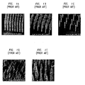
- FIGs. 1A-1 E show different illustrative prior art arrangements of nanoposts produced using various methods and further show that such various diameter nanoposts can be fashioned with different degrees of regularity. These figures show that it is possible to produce nanoposts having various diameters separated by various distances.
- An illustrative method of producing nanoposts found in U.S. Patent No. 6,185,961, titled “Nanopost arrays and process for making same," issued February 13, 2001 to Tonucci, et al, is hereby incorporated by reference herein in its entirety.
- Nanoposts have been manufactured by various methods, such as by using a template to form the posts, by various means of lithography, and by various methods of etching.
- the terms nanostructures/nanoposts and microstructures/microposts are used interchangeably. Throughout the description herein, one skilled in the art will recognize that the same principles applied to the use of nanoposts or nanostructures can be equally applied to microposts or other larger features in a feature pattern.
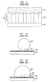
- FIG. 3A shows a macro view of the droplet 201 of FIG. 2 when it is suspended on top of the nanostructure feature pattern 202.
- the droplet in FIG. 3A does not penetrate the feature pattern 202 and, accordingly, experiences a low flow resistance.
- FIG. 3B shows illustrative droplet 201 in a configuration in which it does penetrate feature pattern 202.
- the droplet 201 penetrates the feature pattern 202
- the droplet becomes relatively immobile, i.e., it experiences a relatively high degree of flow resistance.
- a liquid droplet will penetrate a feature pattern, for example, when the surface tension of the liquid droplet is sufficiently low.
- FIGs. 4A and 4B show such a prior art embodiment of one method useful to cause the droplet 201 to penetrate a nanostructure feature pattern.
- FIG. 4A illustrates, for example, the area 301 in FIG. 3 of droplet 201 in contact with feature pattern 202.
- droplet 201 is illustratively a conducting liquid and is disposed on nanostructure feature pattern 202 of conical nanposts. As described above and illustrated in FIG. 3A, the surface tension of the droplet 201 is such that the droplet 201 is suspended on the upper portion of the feature pattern 202. In this arrangement, the droplet 201 only covers surface area f 1 of each nanopost.
- the nanoposts of feature pattern 202 are supported by the surface of a conducting substrate 203.
- Droplet 201 is held illustratively at an electrical potential difference with respect to substrate 203, applied by voltage source 401 through lead 402.
- FIG. 4B shows that, by applying a low voltage (e.g., 10 - 20 volts) to the conducting droplet of liquid 201, a voltage difference results between the liquid 201 and the nanoposts of feature pattern 202.
- a low voltage e.g. 10 - 20 volts
- the contact angle of droplet 201 decreases and droplet 201 moves down in the y-direction along the surface of the nanoposts and penetrates the nanostructure feature pattern 202 until it completely surrounds each of the nanoposts and comes into contact with the upper surface of substrate 203.
- the droplet covers surface area f 2 of each nanopost.
- the overall contact area between the droplet 201 and the nanoposts of feature pattern 202 is relatively high and, accordingly, the flow resistance experienced by the droplet 201 is greater than in the embodiment of FIG. 4A.
- the droplet 201 effectively becomes stationary relative to the nanostructure feature pattern in the absence of another force sufficient to dislodge the droplet 201 from the feature pattern 202.
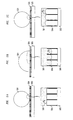
- FIGs. 5A, 5B and 5C illustrate such a selective/reversible penetration of droplet 501 into pattern 504.
- FIG. 5A shows an illustrative droplet 501 disposed on a nanostructure or microstructure feature pattern 504 that is supported by substrate 505. The angle of contact between the droplet and the feature pattern is shown as ⁇ 1 .
- droplet 501 is caused to penetrate the feature pattern 504.
- the angle of contact between the droplet and the feature pattern increases in this case to ⁇ 2 as the droplet moves down along the individual elements (e.g., nanoposts) toward substrate 505.
- the contact angle between the droplet and the feature pattern is as low or lower than ⁇ 1 .
- the contact angle between the droplet 501 and the feature pattern 504 is shown as ⁇ 3 , which is illustratively a smaller angle than ⁇ 1 .
- FIGs. 6A and 6B show, respectively, a three-dimensional view and a top cross-sectional view of an illustrative feature pattern in accordance with the principles of the present invention that is capable of accomplishing the reversible penetration shown in FIGs. 5A-5C.
- the feature pattern does not comprise a number of posts spaced a distance away from each other.
- a number of closed cells here illustrative cells of a hexagonal cross section, are used.
- the term closed cell is defined as a cell that is enclosed on all sides except for the side upon which a liquid is or could be disposed.
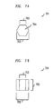
- FIGs. 7A and 7B show a top cross-sectional view and a side view of an illustrative individual cell of the feature pattern of FIGs. 6A and 6B.
- each individual cell 701 is characterized by a maximum width 702 of width d, an individual side length 703 of length d/2 and a wall thickness 704 of thickness t.
- the height 705 of cell 701 is height h.
- FIGs. 8A, 8B and 8C show how an illustrative closed-cell feature pattern similar to the feature pattern of FIGs. 6A and 6B, here shown in cross-section, may be used illustratively to cause a droplet 801 of liquid to reversibly penetrate the feature pattern.
- each cell within feature pattern 804, such as cell 701 having a hexagonal cross-section is a completely closed cell once the droplet of liquid covers the opening of that cell.
- the term fluid is intended to encompass both gases (such as, illustratively, air) and liquids that could be disposed within the cells of the feature pattern.
- gases such as, illustratively, air
- the liquid droplet 801 can be either drawn into the cells or, alternatively, repelled out of the cell.
- the initial pressure i.e., P ⁇ P 0
- the contact angle of the droplet with the feature pattern will increase from ⁇ 1 to ⁇ 2 and the droplet above that cell will be drawn into the cell a distance related to the magnitude in reduction of the pressure P.
- Such a reduction in pressure may be achieved, illustratively, by reducing the temperature of the fluid within the cells such that T ⁇ T 0 .
- Such a temperature reduction may be achieved, illustratively, by reducing the temperature of the substrate 805 and/or the feature pattern 804.
- the temperature of the fluid may be reduced by well-known conduction/convection principles and, accordingly, the pressure within the cell will drop.
- any method of reducing the pressure within the cells including any other method of reducing the temperature of the fluid within the cells, will have similar results.
- FIG. 8C shows how, by increasing the pressure to or above the initial pressure P 0 , it is possible to reverse the penetration of the droplet 801.
- a pressure increase may be achieved by changing the temperature of the fluid within the cells, illustratively in FIG. 8C to a temperature greater than the initial temperature T 0 .
- the increased temperature will increase the pressure within the cells above the initial pressure P 0 .
- the contact angle between the droplet and the elements of the feature pattern will thus change to ⁇ 3 , which is smaller than ⁇ 1 and the liquid will move out of the cells, thus returning droplet 801 to a very low flow resistance contact with feature pattern 804.
- any method of increasing the pressure within the cells to reverse the penetration of the droplet 801 will have similar results.
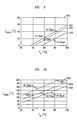
- FIG. 9 shows a graph 904 of the temperature (T trans ) necessary to achieve a 120 degree contact angle of advancement ( ⁇ 2 in FIG. 8B) in order to achieve penetration of the droplet into a feature pattern.
- FIG. 9 assumes a cell height h of 160 microns and a droplet interfacial tension of 62 mN/m. With these conditions, FIG. 9 shows that, for an initial temperature T 0 of the fluid within the cells and for a representative width d (represented by plots 901, 902 and 903 and shown in FIGs. 7A and 7B as dimension 702), there is a given temperature (T trans ) at or below which a droplet will penetrate the feature pattern.
- the pressure will drop sufficiently to cause the droplet to penetrate the feature pattern at or below a transition temperature T trans of approximately 15 degrees Celsius, represented by point 905 on plot 902.
- FIG. 10 shows a graph 1004 having plots 1001, 1002 and 1003 representing different cell widths d, discussed above.
- the interfacial tension of the droplet is assumed to be 62 mN/m and the cell height h is assumed to be 160 microns.
- FIG. 10 shows the temperature change necessary to achieve a 0 degree contact angle ( ⁇ 2 in FIG. 8B) which is the smallest contact angle theoretically achievable to reverse the penetration of the droplet after it has penetrated the feature pattern.
- the '285 application discloses how open-celled nanostructure feature patterns, when used on a submersible vehicle such as a submarine or a torpedo, will dramatically reduce the friction (drag) caused by flow resistance of, illustratively, water passing across the surface of the underwater vehicle.
- drag drag
- the present inventors have recognized that, when the pressure of the water exceeds a certain threshold (depending upon the characteristics of the feature pattern), the water will penetrate the feature pattern, possibly dramatically increasing the drag on the submersible vehicle. Therefore, the present inventors have further recognized that it is desirable to prevent the water from penetrating the feature pattern even in the presence of relatively high pressure.
- FIGs. 11A and 11 B show one illustrative embodiment in accordance with the principles of the present invention whereby liquid is prevented from penetrating a feature pattern even when that liquid is at a relatively high pressure.
- 11A is at an ambient pressure P 0 .
- the feature pattern of FIGs. 11A and 11 B is disposed on the surface of a submarine, when the submarine is traveling on the surface of water at least a portion of the cells will have an initial pressure of the air surrounding the submarine.
- the submarine submerges however, as is illustratively represented by FIG. 11 B, the water begins to exert a pressure P 2 onto the feature pattern, thus resulting in a contact angle ⁇ between the liquid and the pattern.
- the resulting increased contact angle will correspondingly increase the pressure of the fluid (e.g., air) within the cell from P 0 to P 1 .
- the fluid e.g., air
- the contact angle ⁇ will increase and, as a result, the pressure P 1 within the cell will similarly increase.
- the pressure P 2 and hence the contact angle ⁇ will become too great and the water 1102 will penetrate the feature pattern 1103 until it contacts substrate 1101.
- a certain pressure limit there will be a range of pressures (that correspond to depths in water for the illustrative example of a submarine) for which the water will not penetrate the feature pattern.
- the submersible vehicle can submerge to a depth much greater without penetration of the feature pattern than would be the case where an open-celled feature pattern of, for example, nanoposts, were used.
- an open-celled feature pattern of, for example, nanoposts were used.
- low flow resistance can be maintained to a much greater depth that using such an open pattern.
- FIG. 12 shows a graph 1204 with plots 1201, 1202 and 1203 that illustrate how different pressures within the cells of the feature pattern of FIGs. 11A and 11B will result in a specific contact angle when the cells are defined by a particular height to width ratio (h/r).
- Plots 1202 and 1203 show how changes in the pressure P 1 will result in different contact angles for given cell dimensions.
- One skilled in the art will readily be able to develop different plots for different contact angles other than those shown in FIG. 12.
- FIG. 12 also shows that, for pressures and cell dimension combinations that fall within area 1205 of graph 1204, there are no solutions that would lead to an unpenetrated surface of the feature pattern.
- a pressure P 1 that is 5 times the initial ambient pressure P 0 , will lead to penetration of the feature pattern.
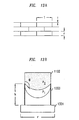
- FIGs. 13A and 13B show an illustrative cell configuration that will prevent the penetration of water into the feature pattern at significantly greater pressures.
- the height of the individual cells is, illustratively, the same as the height h (.25 microns) of the cells of FIG. 11 B.
- FIG. 13B shows, however, that instead of being rectangular in side cross section, as were the cells in FIG.
- the cells of 13B are rounded at the bottom and, thus, each cell is capable of holding less fluid (e.g., air).
- fluid e.g., air
- the pressure P 2 rises and compresses the fluid within the cell
- the pressure P 1 rises more quickly than was the case in the embodiment of FIGs. 11A and 11B.
- the cell can withstand a much higher pressure of water before the liquid will penetrate the cells of the feature pattern.
- FIG. 14 shows a graph 1404 with plots 1401, 1402 and 1403 that illustrate how different pressures within the cells of the feature pattern of FIGs. 13A and 13B will result in a specific contact angle when the cells are defined by a particular height to width ratio (h/r).
- h/r height to width ratio
- a contact angle of approximately 110 degrees will result from a pressure P 1 of 5 times the initial ambient pressure P 0 .
- point 1406 shows that, for a slightly higher cell height to width ratio of .18, a contact angle of 120 degrees will result from a pressure P 1 of 6 times the initial ambient pressure P 0 .
- a contact angle of 120 degrees is practically limitless with regard to the pressure P 1 that can be withstood without penetration of the feature pattern. Accordingly, the low-flow properties of the surface remain intact and, in the case of a submarine, a low friction (drag) will continue to be experienced even at great water pressures/depths.
- penetration of a liquid into a feature pattern and the reversing of that penetration may be accomplished by other means other than increasing or decreasing the temperature of the fluid within closed cells. For example, air may be blown/withdrawn into/from the cells, thus increasing/decreasing, respectively, the pressure within those cells.
Landscapes
- Chemical & Material Sciences (AREA)
- Engineering & Computer Science (AREA)
- Nanotechnology (AREA)
- Crystallography & Structural Chemistry (AREA)
- Health & Medical Sciences (AREA)
- Physics & Mathematics (AREA)
- General Health & Medical Sciences (AREA)
- Optics & Photonics (AREA)
- Biophysics (AREA)
- Analytical Chemistry (AREA)
- Life Sciences & Earth Sciences (AREA)
- Hematology (AREA)
- Clinical Laboratory Science (AREA)
- Chemical Kinetics & Catalysis (AREA)
- General Engineering & Computer Science (AREA)
- Microelectronics & Electronic Packaging (AREA)
- Computer Hardware Design (AREA)
- Theoretical Computer Science (AREA)
- Fluid Mechanics (AREA)
- Mechanical Engineering (AREA)
- Manufacturing & Machinery (AREA)
- Physical Or Chemical Processes And Apparatus (AREA)
- Micromachines (AREA)
Applications Claiming Priority (2)
| Application Number | Priority Date | Filing Date | Title |
|---|---|---|---|
| US10/674,448 US8124423B2 (en) | 2003-09-30 | 2003-09-30 | Method and apparatus for controlling the flow resistance of a fluid on nanostructured or microstructured surfaces |
| US674448 | 2003-09-30 |
Publications (2)
| Publication Number | Publication Date |
|---|---|
| EP1520622A1 true EP1520622A1 (fr) | 2005-04-06 |
| EP1520622B1 EP1520622B1 (fr) | 2010-05-26 |
Family
ID=34313960
Family Applications (1)
| Application Number | Title | Priority Date | Filing Date |
|---|---|---|---|
| EP20040255627 Expired - Lifetime EP1520622B1 (fr) | 2003-09-30 | 2004-09-16 | Procédé et dispositif pour la regulation de la résistance à l'écoulement de liquides sur les surfaces avec nano- ou microstructures |
Country Status (6)
| Country | Link |
|---|---|
| US (2) | US8124423B2 (fr) |
| EP (1) | EP1520622B1 (fr) |
| JP (1) | JP4965799B2 (fr) |
| KR (1) | KR101190521B1 (fr) |
| CN (1) | CN100579657C (fr) |
| DE (1) | DE602004027333D1 (fr) |
Cited By (4)
| Publication number | Priority date | Publication date | Assignee | Title |
|---|---|---|---|---|
| WO2006122697A1 (fr) * | 2005-05-17 | 2006-11-23 | Commissariat A L'energie Atomique | Composant microfluidique comprenant au moins un canal rempli de nanotubes et procede de production d'un tel composant microfluidique |
| WO2007041080A1 (fr) * | 2005-09-30 | 2007-04-12 | Lucent Technologies Inc. | Surfaces transformables physiquement sous l'effet de modifications de l'environnement |
| WO2008027330A3 (fr) * | 2006-08-30 | 2008-06-12 | Lucent Technologies Inc | Surfaces de cellules fermées aux propriétés de réduction de traînée améliorées |
| EP2058277B1 (fr) * | 2007-11-09 | 2011-06-22 | Lucent Technologies Inc. | Appareil avec une surface ayant des cellules couplées en bulles pour une réduction de traînée améliorée d'un fluide et procédé associé |
Families Citing this family (32)
| Publication number | Priority date | Publication date | Assignee | Title |
|---|---|---|---|---|
| US20040191127A1 (en) | 2003-03-31 | 2004-09-30 | Avinoam Kornblit | Method and apparatus for controlling the movement of a liquid on a nanostructured or microstructured surface |
| US8124423B2 (en) | 2003-09-30 | 2012-02-28 | Alcatel Lucent | Method and apparatus for controlling the flow resistance of a fluid on nanostructured or microstructured surfaces |
| US7785733B2 (en) * | 2003-11-18 | 2010-08-31 | Alcatel-Lucent Usa Inc. | Reserve cell-array nanostructured battery |
| JP4237610B2 (ja) * | 2003-12-19 | 2009-03-11 | 株式会社東芝 | 保守支援方法及びプログラム |
| US7323033B2 (en) * | 2004-04-30 | 2008-01-29 | Lucent Technologies Inc. | Nanostructured surfaces having variable permeability |
| US7608446B2 (en) * | 2004-09-30 | 2009-10-27 | Alcatel-Lucent Usa Inc. | Nanostructured surface for microparticle analysis and manipulation |
| US7204298B2 (en) | 2004-11-24 | 2007-04-17 | Lucent Technologies Inc. | Techniques for microchannel cooling |
| JP3978500B2 (ja) * | 2005-02-18 | 2007-09-19 | 国立大学法人埼玉大学 | 多種微量試料の注入、移行方法 |
| US7666665B2 (en) | 2005-08-31 | 2010-02-23 | Alcatel-Lucent Usa Inc. | Low adsorption surface |
| US8734003B2 (en) | 2005-09-15 | 2014-05-27 | Alcatel Lucent | Micro-chemical mixing |
| US20070059213A1 (en) * | 2005-09-15 | 2007-03-15 | Lucent Technologies Inc. | Heat-induced transitions on a structured surface |
| US8721161B2 (en) | 2005-09-15 | 2014-05-13 | Alcatel Lucent | Fluid oscillations on structured surfaces |
| US7412938B2 (en) * | 2005-09-15 | 2008-08-19 | Lucent Technologies Inc. | Structured surfaces with controlled flow resistance |
| US8287808B2 (en) * | 2005-09-15 | 2012-10-16 | Alcatel Lucent | Surface for reversible wetting-dewetting |
| US20070259156A1 (en) * | 2006-05-03 | 2007-11-08 | Lucent Technologies, Inc. | Hydrophobic surfaces and fabrication process |
| US7449649B2 (en) * | 2006-05-23 | 2008-11-11 | Lucent Technologies Inc. | Liquid switch |
| US8047235B2 (en) * | 2006-11-30 | 2011-11-01 | Alcatel Lucent | Fluid-permeable body having a superhydrophobic surface |
| US8794574B2 (en) * | 2007-03-30 | 2014-08-05 | The Board Of Trustees Of The University Of Alabama | Micro-array surface for passive drag modification |
| WO2012015700A2 (fr) * | 2010-07-27 | 2012-02-02 | The Regents Of The University Of California | Procédé et dispositif de rétablissement et de maintien de la superhydrophobicité sous liquide |
| US20140141503A1 (en) * | 2012-11-20 | 2014-05-22 | Corning Incorporated | Cell culture substrate having uniform surface coating |
| US20140238646A1 (en) * | 2013-02-25 | 2014-08-28 | Alcatel-Lucent Ireland Ltd. | Sloped hierarchically-structured surface designs for enhanced condensation heat transfer |
| DE102013111759A1 (de) * | 2013-10-25 | 2015-04-30 | Bürkert Werke GmbH | Vorrichtung und Verfahren zur Untersuchung von Probenflüssigkeit |
| JP2015171754A (ja) * | 2014-03-12 | 2015-10-01 | 大日本印刷株式会社 | マイクロ流路装置 |
| RU2581342C2 (ru) * | 2014-06-06 | 2016-04-20 | Федеральное государственное бюджетное учреждение науки Институт теплофизики им. С.С. Кутателадзе Сибирского отделения Российской академии наук (ИТ СО РАН) | Способ изготовления системы охлаждения электронного и микроэлектронного оборудования |
| US11346087B2 (en) * | 2016-05-13 | 2022-05-31 | Kansas State University Research Foundation | Nanopatterned surfaces and methods for accelerated freezing and liquid recovery |
| US20180029070A1 (en) | 2016-08-01 | 2018-02-01 | Ho Young Yun | Liquid patterning device and method |
| CN108107918B (zh) * | 2018-01-11 | 2023-11-17 | 广州航海学院 | 控制液滴移动方向的装置与方法 |
| CN109625154B (zh) * | 2018-12-10 | 2021-01-01 | 武汉大学 | 一种仿生微腔减阻结构 |
| CN109611419B (zh) * | 2018-12-11 | 2021-04-02 | 吉林大学 | 一种金属基水下仿生气膜减阻表面及其制备方法与应用 |
| JP7229110B2 (ja) * | 2019-06-25 | 2023-02-27 | 株式会社Screenホールディングス | 細胞電位測定装置 |
| CN114682312B (zh) * | 2022-03-30 | 2023-06-13 | 北京航空航天大学 | 基于硅基的液滴自运输微结构及运输方法 |
| CN116174070B (zh) * | 2023-02-23 | 2024-04-19 | 华中科技大学 | 一种基于微纳结构放电的定向运输液滴的装置及方法 |
Citations (6)
| Publication number | Priority date | Publication date | Assignee | Title |
|---|---|---|---|---|
| EP0290125A2 (fr) * | 1987-05-05 | 1988-11-09 | Molecular Devices Corporation | Microplatines hydrophiles pour la photométrie à rayons verticaux |
| DE19705910C1 (de) * | 1997-02-15 | 1998-06-18 | Inst Physikalische Hochtech Ev | Mikrokammerarray mit hoher Kammerdichte |
| WO2003056330A2 (fr) * | 2001-12-31 | 2003-07-10 | Institut für Physikalische Hochtechnologie e.V. | Systeme de tri de cellules conçu pour trier ou separer des cellules en suspension dans un liquide en ecoulement en fonction de leur grandeur |
| US20030148401A1 (en) * | 2001-11-09 | 2003-08-07 | Anoop Agrawal | High surface area substrates for microarrays and methods to make same |
| WO2003071335A2 (fr) * | 2002-02-20 | 2003-08-28 | Koninklijke Philips Electronics N.V. | Appareil d'affichage |
| WO2003083447A1 (fr) * | 2002-03-22 | 2003-10-09 | Diversa Corporation | Procede d'intensification de la detection optique d'echantillons contenus en solution dans des puits traversants d'un plateau de reception |
Family Cites Families (24)
| Publication number | Priority date | Publication date | Assignee | Title |
|---|---|---|---|---|
| DE3528135A1 (de) * | 1985-08-06 | 1987-04-02 | Messerschmitt Boelkow Blohm | Einrichtung zur verringerung des reibungswiderstandes |
| US4728591A (en) * | 1986-03-07 | 1988-03-01 | Trustees Of Boston University | Self-assembled nanometer lithographic masks and templates and method for parallel fabrication of nanometer scale multi-device structures |
| JPH02149675A (ja) * | 1988-11-29 | 1990-06-08 | Kanzaki Paper Mfg Co Ltd | 多孔質体の内部メッキ方法 |
| US5459300A (en) * | 1993-03-03 | 1995-10-17 | Kasman; David H. | Microplate heater for providing uniform heating regardless of the geometry of the microplates |
| JP3604182B2 (ja) * | 1994-11-24 | 2004-12-22 | 大日本印刷株式会社 | 基板面端部の過剰塗布液除去方法および装置 |
| US6241333B1 (en) * | 1997-01-14 | 2001-06-05 | Eastman Kodak Company | Ink jet printhead for multi-level printing |
| BR9810527A (pt) * | 1997-06-16 | 2000-12-19 | Dartmouth College | Sistemas e métodos para modificar resistência a adesão de gelo |
| JPH1138336A (ja) | 1997-07-18 | 1999-02-12 | Fujitsu Ltd | 光スイッチング素子 |
| JP3880212B2 (ja) * | 1997-08-08 | 2007-02-14 | キヤノン株式会社 | インクジェット記録方法 |
| US6185961B1 (en) * | 1999-01-27 | 2001-02-13 | The United States Of America As Represented By The Secretary Of The Navy | Nanopost arrays and process for making same |
| JP2000356750A (ja) * | 1999-06-16 | 2000-12-26 | Canon Inc | 表示素子および表示装置 |
| JP2001207123A (ja) * | 1999-11-16 | 2001-07-31 | Sentan Kagaku Gijutsu Incubation Center:Kk | 高硬度高滑水性膜およびその製造方法 |
| GB0110994D0 (en) * | 2001-05-04 | 2001-06-27 | Crawford Charles G | Personal story and event organiser |
| US20040191127A1 (en) | 2003-03-31 | 2004-09-30 | Avinoam Kornblit | Method and apparatus for controlling the movement of a liquid on a nanostructured or microstructured surface |
| US7156032B2 (en) | 2003-08-22 | 2007-01-02 | Lucent Technologies Inc. | Method and apparatus for controlling friction between a fluid and a body |
| US8124423B2 (en) | 2003-09-30 | 2012-02-28 | Alcatel Lucent | Method and apparatus for controlling the flow resistance of a fluid on nanostructured or microstructured surfaces |
| US7785733B2 (en) | 2003-11-18 | 2010-08-31 | Alcatel-Lucent Usa Inc. | Reserve cell-array nanostructured battery |
| US7227235B2 (en) | 2003-11-18 | 2007-06-05 | Lucent Technologies Inc. | Electrowetting battery having a nanostructured electrode surface |
| US8915957B2 (en) | 2004-03-11 | 2014-12-23 | Alcatel Lucent | Drug delivery stent |
| US7618746B2 (en) | 2004-03-18 | 2009-11-17 | Alcatel-Lucent Usa Inc. | Nanostructured battery having end of life cells |
| US7749646B2 (en) | 2004-03-18 | 2010-07-06 | Alcatel-Lucent Usa Inc. | Reversibly-activated nanostructured battery |
| US7048889B2 (en) | 2004-03-23 | 2006-05-23 | Lucent Technologies Inc. | Dynamically controllable biological/chemical detectors having nanostructured surfaces |
| US20050211505A1 (en) | 2004-03-26 | 2005-09-29 | Kroupenkine Timofei N | Nanostructured liquid bearing |
| US7005593B2 (en) | 2004-04-01 | 2006-02-28 | Lucent Technologies Inc. | Liquid electrical microswitch |
-
2003
- 2003-09-30 US US10/674,448 patent/US8124423B2/en active Active
-
2004
- 2004-09-16 DE DE200460027333 patent/DE602004027333D1/de not_active Expired - Lifetime
- 2004-09-16 EP EP20040255627 patent/EP1520622B1/fr not_active Expired - Lifetime
- 2004-09-23 KR KR1020040076491A patent/KR101190521B1/ko not_active Expired - Fee Related
- 2004-09-28 JP JP2004281534A patent/JP4965799B2/ja not_active Expired - Fee Related
- 2004-09-28 CN CN200410012073A patent/CN100579657C/zh not_active Expired - Fee Related
-
2011
- 2011-11-22 US US13/301,964 patent/US8187894B2/en not_active Expired - Fee Related
Patent Citations (6)
| Publication number | Priority date | Publication date | Assignee | Title |
|---|---|---|---|---|
| EP0290125A2 (fr) * | 1987-05-05 | 1988-11-09 | Molecular Devices Corporation | Microplatines hydrophiles pour la photométrie à rayons verticaux |
| DE19705910C1 (de) * | 1997-02-15 | 1998-06-18 | Inst Physikalische Hochtech Ev | Mikrokammerarray mit hoher Kammerdichte |
| US20030148401A1 (en) * | 2001-11-09 | 2003-08-07 | Anoop Agrawal | High surface area substrates for microarrays and methods to make same |
| WO2003056330A2 (fr) * | 2001-12-31 | 2003-07-10 | Institut für Physikalische Hochtechnologie e.V. | Systeme de tri de cellules conçu pour trier ou separer des cellules en suspension dans un liquide en ecoulement en fonction de leur grandeur |
| WO2003071335A2 (fr) * | 2002-02-20 | 2003-08-28 | Koninklijke Philips Electronics N.V. | Appareil d'affichage |
| WO2003083447A1 (fr) * | 2002-03-22 | 2003-10-09 | Diversa Corporation | Procede d'intensification de la detection optique d'echantillons contenus en solution dans des puits traversants d'un plateau de reception |
Non-Patent Citations (1)
| Title |
|---|
| BECKER E W ET AL: "FABRICATION OF MICROSTRUCTURES WITH HIGH ASPECT RATIOS AND GREAT STRUCTURAL HEIGHTS BY SYNCHROTRON RADIATION LITHOGRAPHY, GALVANOFORMING, AND PLASTIC MOULDING (LIGA PROCESS)", MICROELECTRONIC ENGINEERING, ELSEVIER PUBLISHERS BV., AMSTERDAM, NL, vol. 4, no. 1, 1 May 1986 (1986-05-01), pages 35 - 56, XP000051563, ISSN: 0167-9317 * |
Cited By (16)
| Publication number | Priority date | Publication date | Assignee | Title |
|---|---|---|---|---|
| US8293193B2 (en) | 2005-05-17 | 2012-10-23 | Commissariat A L'energie Atomique | Microfluidic component with a channel filled with nanotubes and method for its production |
| FR2885898A1 (fr) * | 2005-05-17 | 2006-11-24 | Commissariat Energie Atomique | Composant microfluidique comprenant au moins un canal rempli de nanotubes et procede de fabrication d'un tel composant microfluidique. |
| WO2006122697A1 (fr) * | 2005-05-17 | 2006-11-23 | Commissariat A L'energie Atomique | Composant microfluidique comprenant au moins un canal rempli de nanotubes et procede de production d'un tel composant microfluidique |
| CN101175991B (zh) * | 2005-05-17 | 2011-08-10 | 原子能委员会 | 带有填充纳米管的通道的微流控器件及其生产方法 |
| US8084116B2 (en) | 2005-09-30 | 2011-12-27 | Alcatel Lucent | Surfaces physically transformable by environmental changes |
| JP2009509783A (ja) * | 2005-09-30 | 2009-03-12 | ルーセント テクノロジーズ インコーポレーテッド | 環境変化によって物理的に変質可能な表面 |
| WO2007041080A1 (fr) * | 2005-09-30 | 2007-04-12 | Lucent Technologies Inc. | Surfaces transformables physiquement sous l'effet de modifications de l'environnement |
| US8425828B2 (en) | 2005-09-30 | 2013-04-23 | Alcatel Lucent | Surfaces physically transformable by environmental changes |
| US8691362B2 (en) | 2005-09-30 | 2014-04-08 | Alcatel Lucent | Surfaces physically transformable by environmental changes |
| JP2010501959A (ja) * | 2006-08-30 | 2010-01-21 | アルカテル−ルーセント ユーエスエー インコーポレーテッド | 向上した前進抵抗低減プロパティを持つ閉セル表面 |
| US7700183B2 (en) | 2006-08-30 | 2010-04-20 | Alcatel-Lucent Usa Inc. | Closed cell surfaces with enhanced drag-reduction properties |
| WO2008027330A3 (fr) * | 2006-08-30 | 2008-06-12 | Lucent Technologies Inc | Surfaces de cellules fermées aux propriétés de réduction de traînée améliorées |
| US8247028B2 (en) | 2006-08-30 | 2012-08-21 | Alcatel Lucent | Method of using closed cell surfaces with enhanced drag-reduction properties |
| US20120227243A1 (en) * | 2006-08-30 | 2012-09-13 | Marc Scott Hodes | Closed cell surfaces with enhanced drag-reduction properties |
| US8541052B2 (en) | 2006-08-30 | 2013-09-24 | Alcatel Lucent | Method of manufacturing closed-cell surfaces with advanced drag-reduction properties |
| EP2058277B1 (fr) * | 2007-11-09 | 2011-06-22 | Lucent Technologies Inc. | Appareil avec une surface ayant des cellules couplées en bulles pour une réduction de traînée améliorée d'un fluide et procédé associé |
Also Published As
| Publication number | Publication date |
|---|---|
| EP1520622B1 (fr) | 2010-05-26 |
| CN1603226A (zh) | 2005-04-06 |
| US8187894B2 (en) | 2012-05-29 |
| CN100579657C (zh) | 2010-01-13 |
| KR20050031928A (ko) | 2005-04-06 |
| US20120060937A1 (en) | 2012-03-15 |
| JP4965799B2 (ja) | 2012-07-04 |
| US8124423B2 (en) | 2012-02-28 |
| DE602004027333D1 (de) | 2010-07-08 |
| KR101190521B1 (ko) | 2012-10-16 |
| JP2005118985A (ja) | 2005-05-12 |
| US20050069458A1 (en) | 2005-03-31 |
Similar Documents
| Publication | Publication Date | Title |
|---|---|---|
| US8187894B2 (en) | Method and apparatus for controlling the flow resistance of a fluid on nanostructured or microstructured surfaces | |
| EP1591415B1 (fr) | Surface nano-structurée avec perméabilité variable | |
| Yang et al. | Creation of topological ultraslippery surfaces for droplet motion control | |
| JP5210417B2 (ja) | ナノストラクチャまたはマイクロストラクチャ表面の液体の移動を制御するための方法および装置 | |
| Cho et al. | Creating, transporting, cutting, and merging liquid droplets by electrowetting-based actuation for digital microfluidic circuits | |
| Sen et al. | Scaling laws in directional spreading of droplets on wettability-confined diverging tracks | |
| Zhu et al. | Tuning wettability and getting superhydrophobic surface by controlling surface roughness with well-designed microstructures | |
| DE69938602T2 (de) | Proportionale, mikromechanische vorrichtung | |
| US8287808B2 (en) | Surface for reversible wetting-dewetting | |
| Almeida et al. | Virtual walls based on oil-repellent surfaces for low-surface-tension liquids | |
| KR101887075B1 (ko) | 마찰항력 저감을 위한 3중 초발수 구조 필름 및 그 제조방법 | |
| EP1618035A2 (fr) | Dispositif microfluidique a surfaces ultraphobiques | |
| CN101300702B (zh) | 具有偏向润湿表面的流体处理装置 | |
| US7455021B2 (en) | Method and apparatus for controlling friction between a fluid and a body | |
| TWI888432B (zh) | 極微結構化表面 | |
| Erdem | Microfluidic Reactors for the Controlled Synthesis of Nanoparticles | |
| Altintas et al. | Numerical and experimental characterization of 3-phase rectification of nanobead dielectrophoretic transport exploiting Brownian motion | |
| Zellner et al. | CMOS-compatible three dimensional buried channel technology (3DBCT) | |
| WO2015092611A1 (fr) | Dispositif permettant de commander l'écoulement d'un liquide | |
| Dangla et al. | Drops on rails |
Legal Events
| Date | Code | Title | Description |
|---|---|---|---|
| PUAI | Public reference made under article 153(3) epc to a published international application that has entered the european phase |
Free format text: ORIGINAL CODE: 0009012 |
|
| 17P | Request for examination filed |
Effective date: 20040927 |
|
| AK | Designated contracting states |
Kind code of ref document: A1 Designated state(s): AT BE BG CH CY CZ DE DK EE ES FI FR GB GR HU IE IT LI LU MC NL PL PT RO SE SI SK TR |
|
| AX | Request for extension of the european patent |
Extension state: AL HR LT LV MK |
|
| AKX | Designation fees paid |
Designated state(s): DE FR GB |
|
| GRAP | Despatch of communication of intention to grant a patent |
Free format text: ORIGINAL CODE: EPIDOSNIGR1 |
|
| GRAJ | Information related to disapproval of communication of intention to grant by the applicant or resumption of examination proceedings by the epo deleted |
Free format text: ORIGINAL CODE: EPIDOSDIGR1 |
|
| RAP3 | Party data changed (applicant data changed or rights of an application transferred) |
Owner name: LUCENT TECHNOLOGIES INC. |
|
| GRAP | Despatch of communication of intention to grant a patent |
Free format text: ORIGINAL CODE: EPIDOSNIGR1 |
|
| GRAS | Grant fee paid |
Free format text: ORIGINAL CODE: EPIDOSNIGR3 |
|
| GRAA | (expected) grant |
Free format text: ORIGINAL CODE: 0009210 |
|
| AK | Designated contracting states |
Kind code of ref document: B1 Designated state(s): DE FR GB |
|
| REG | Reference to a national code |
Ref country code: GB Ref legal event code: FG4D |
|
| RAP2 | Party data changed (patent owner data changed or rights of a patent transferred) |
Owner name: ALCATEL-LUCENT USA INC. |
|
| REF | Corresponds to: |
Ref document number: 602004027333 Country of ref document: DE Date of ref document: 20100708 Kind code of ref document: P |
|
| PLBE | No opposition filed within time limit |
Free format text: ORIGINAL CODE: 0009261 |
|
| STAA | Information on the status of an ep patent application or granted ep patent |
Free format text: STATUS: NO OPPOSITION FILED WITHIN TIME LIMIT |
|
| 26N | No opposition filed |
Effective date: 20110301 |
|
| REG | Reference to a national code |
Ref country code: DE Ref legal event code: R097 Ref document number: 602004027333 Country of ref document: DE Effective date: 20110228 |
|
| REG | Reference to a national code |
Ref country code: GB Ref legal event code: 732E Free format text: REGISTERED BETWEEN 20131024 AND 20131030 |
|
| REG | Reference to a national code |
Ref country code: FR Ref legal event code: GC Effective date: 20140715 |
|
| REG | Reference to a national code |
Ref country code: FR Ref legal event code: RG Effective date: 20141015 |
|
| REG | Reference to a national code |
Ref country code: FR Ref legal event code: PLFP Year of fee payment: 12 |
|
| REG | Reference to a national code |
Ref country code: FR Ref legal event code: PLFP Year of fee payment: 13 |
|
| REG | Reference to a national code |
Ref country code: FR Ref legal event code: PLFP Year of fee payment: 14 |
|
| REG | Reference to a national code |
Ref country code: FR Ref legal event code: PLFP Year of fee payment: 15 |
|
| PGFP | Annual fee paid to national office [announced via postgrant information from national office to epo] |
Ref country code: DE Payment date: 20190903 Year of fee payment: 16 |
|
| PGFP | Annual fee paid to national office [announced via postgrant information from national office to epo] |
Ref country code: GB Payment date: 20200909 Year of fee payment: 17 Ref country code: FR Payment date: 20200812 Year of fee payment: 17 |
|
| REG | Reference to a national code |
Ref country code: DE Ref legal event code: R119 Ref document number: 602004027333 Country of ref document: DE |
|
| PG25 | Lapsed in a contracting state [announced via postgrant information from national office to epo] |
Ref country code: DE Free format text: LAPSE BECAUSE OF NON-PAYMENT OF DUE FEES Effective date: 20210401 |
|
| GBPC | Gb: european patent ceased through non-payment of renewal fee |
Effective date: 20210916 |
|
| PG25 | Lapsed in a contracting state [announced via postgrant information from national office to epo] |
Ref country code: GB Free format text: LAPSE BECAUSE OF NON-PAYMENT OF DUE FEES Effective date: 20210916 Ref country code: FR Free format text: LAPSE BECAUSE OF NON-PAYMENT OF DUE FEES Effective date: 20210930 |