EP1520744A2 - A system for controlling filling of a motor-vehicle tank with LPG, and a servo valve used therein - Google Patents
A system for controlling filling of a motor-vehicle tank with LPG, and a servo valve used therein Download PDFInfo
- Publication number
- EP1520744A2 EP1520744A2 EP04022157A EP04022157A EP1520744A2 EP 1520744 A2 EP1520744 A2 EP 1520744A2 EP 04022157 A EP04022157 A EP 04022157A EP 04022157 A EP04022157 A EP 04022157A EP 1520744 A2 EP1520744 A2 EP 1520744A2
- Authority
- EP
- European Patent Office
- Prior art keywords
- tank
- lpg
- valve
- solenoid
- filling
- Prior art date
- Legal status (The legal status is an assumption and is not a legal conclusion. Google has not performed a legal analysis and makes no representation as to the accuracy of the status listed.)
- Granted
Links
Images


Classifications
-
- F—MECHANICAL ENGINEERING; LIGHTING; HEATING; WEAPONS; BLASTING
- F17—STORING OR DISTRIBUTING GASES OR LIQUIDS
- F17C—VESSELS FOR CONTAINING OR STORING COMPRESSED, LIQUEFIED OR SOLIDIFIED GASES; FIXED-CAPACITY GAS-HOLDERS; FILLING VESSELS WITH, OR DISCHARGING FROM VESSELS, COMPRESSED, LIQUEFIED, OR SOLIDIFIED GASES
- F17C9/00—Methods or apparatus for discharging liquefied or solidified gases from vessels not under pressure
- F17C9/02—Methods or apparatus for discharging liquefied or solidified gases from vessels not under pressure with change of state, e.g. vaporisation
-
- B—PERFORMING OPERATIONS; TRANSPORTING
- B60—VEHICLES IN GENERAL
- B60K—ARRANGEMENT OR MOUNTING OF PROPULSION UNITS OR OF TRANSMISSIONS IN VEHICLES; ARRANGEMENT OR MOUNTING OF PLURAL DIVERSE PRIME-MOVERS IN VEHICLES; AUXILIARY DRIVES FOR VEHICLES; INSTRUMENTATION OR DASHBOARDS FOR VEHICLES; ARRANGEMENTS IN CONNECTION WITH COOLING, AIR INTAKE, GAS EXHAUST OR FUEL SUPPLY OF PROPULSION UNITS IN VEHICLES
- B60K15/00—Arrangement in connection with fuel supply of combustion engines or other fuel consuming energy converters, e.g. fuel cells; Mounting or construction of fuel tanks
-
- F—MECHANICAL ENGINEERING; LIGHTING; HEATING; WEAPONS; BLASTING
- F16—ENGINEERING ELEMENTS AND UNITS; GENERAL MEASURES FOR PRODUCING AND MAINTAINING EFFECTIVE FUNCTIONING OF MACHINES OR INSTALLATIONS; THERMAL INSULATION IN GENERAL
- F16K—VALVES; TAPS; COCKS; ACTUATING-FLOATS; DEVICES FOR VENTING OR AERATING
- F16K31/00—Actuating devices; Operating means; Releasing devices
- F16K31/12—Actuating devices; Operating means; Releasing devices actuated by fluid
- F16K31/36—Actuating devices; Operating means; Releasing devices actuated by fluid in which fluid from the circuit is constantly supplied to the fluid motor
- F16K31/40—Actuating devices; Operating means; Releasing devices actuated by fluid in which fluid from the circuit is constantly supplied to the fluid motor with electrically-actuated member in the discharge of the motor
- F16K31/402—Actuating devices; Operating means; Releasing devices actuated by fluid in which fluid from the circuit is constantly supplied to the fluid motor with electrically-actuated member in the discharge of the motor acting on a diaphragm
-
- F—MECHANICAL ENGINEERING; LIGHTING; HEATING; WEAPONS; BLASTING
- F17—STORING OR DISTRIBUTING GASES OR LIQUIDS
- F17C—VESSELS FOR CONTAINING OR STORING COMPRESSED, LIQUEFIED OR SOLIDIFIED GASES; FIXED-CAPACITY GAS-HOLDERS; FILLING VESSELS WITH, OR DISCHARGING FROM VESSELS, COMPRESSED, LIQUEFIED, OR SOLIDIFIED GASES
- F17C2205/00—Vessel construction, in particular mounting arrangements, attachments or identifications means
- F17C2205/03—Fluid connections, filters, valves, closure means or other attachments
- F17C2205/0302—Fittings, valves, filters, or components in connection with the gas storage device
- F17C2205/0323—Valves
- F17C2205/0326—Valves electrically actuated
-
- F—MECHANICAL ENGINEERING; LIGHTING; HEATING; WEAPONS; BLASTING
- F17—STORING OR DISTRIBUTING GASES OR LIQUIDS
- F17C—VESSELS FOR CONTAINING OR STORING COMPRESSED, LIQUEFIED OR SOLIDIFIED GASES; FIXED-CAPACITY GAS-HOLDERS; FILLING VESSELS WITH, OR DISCHARGING FROM VESSELS, COMPRESSED, LIQUEFIED, OR SOLIDIFIED GASES
- F17C2205/00—Vessel construction, in particular mounting arrangements, attachments or identifications means
- F17C2205/03—Fluid connections, filters, valves, closure means or other attachments
- F17C2205/0302—Fittings, valves, filters, or components in connection with the gas storage device
- F17C2205/0323—Valves
- F17C2205/0335—Check-valves or non-return valves
-
- F—MECHANICAL ENGINEERING; LIGHTING; HEATING; WEAPONS; BLASTING
- F17—STORING OR DISTRIBUTING GASES OR LIQUIDS
- F17C—VESSELS FOR CONTAINING OR STORING COMPRESSED, LIQUEFIED OR SOLIDIFIED GASES; FIXED-CAPACITY GAS-HOLDERS; FILLING VESSELS WITH, OR DISCHARGING FROM VESSELS, COMPRESSED, LIQUEFIED, OR SOLIDIFIED GASES
- F17C2221/00—Handled fluid, in particular type of fluid
- F17C2221/03—Mixtures
- F17C2221/032—Hydrocarbons
- F17C2221/035—Propane butane, e.g. LPG, GPL
-
- F—MECHANICAL ENGINEERING; LIGHTING; HEATING; WEAPONS; BLASTING
- F17—STORING OR DISTRIBUTING GASES OR LIQUIDS
- F17C—VESSELS FOR CONTAINING OR STORING COMPRESSED, LIQUEFIED OR SOLIDIFIED GASES; FIXED-CAPACITY GAS-HOLDERS; FILLING VESSELS WITH, OR DISCHARGING FROM VESSELS, COMPRESSED, LIQUEFIED, OR SOLIDIFIED GASES
- F17C2223/00—Handled fluid before transfer, i.e. state of fluid when stored in the vessel or before transfer from the vessel
- F17C2223/01—Handled fluid before transfer, i.e. state of fluid when stored in the vessel or before transfer from the vessel characterised by the phase
- F17C2223/0146—Two-phase
- F17C2223/0153—Liquefied gas, e.g. LPG, GPL
-
- F—MECHANICAL ENGINEERING; LIGHTING; HEATING; WEAPONS; BLASTING
- F17—STORING OR DISTRIBUTING GASES OR LIQUIDS
- F17C—VESSELS FOR CONTAINING OR STORING COMPRESSED, LIQUEFIED OR SOLIDIFIED GASES; FIXED-CAPACITY GAS-HOLDERS; FILLING VESSELS WITH, OR DISCHARGING FROM VESSELS, COMPRESSED, LIQUEFIED, OR SOLIDIFIED GASES
- F17C2223/00—Handled fluid before transfer, i.e. state of fluid when stored in the vessel or before transfer from the vessel
- F17C2223/03—Handled fluid before transfer, i.e. state of fluid when stored in the vessel or before transfer from the vessel characterised by the pressure level
- F17C2223/033—Small pressure, e.g. for liquefied gas
-
- F—MECHANICAL ENGINEERING; LIGHTING; HEATING; WEAPONS; BLASTING
- F17—STORING OR DISTRIBUTING GASES OR LIQUIDS
- F17C—VESSELS FOR CONTAINING OR STORING COMPRESSED, LIQUEFIED OR SOLIDIFIED GASES; FIXED-CAPACITY GAS-HOLDERS; FILLING VESSELS WITH, OR DISCHARGING FROM VESSELS, COMPRESSED, LIQUEFIED, OR SOLIDIFIED GASES
- F17C2227/00—Transfer of fluids, i.e. method or means for transferring the fluid; Heat exchange with the fluid
- F17C2227/01—Propulsion of the fluid
- F17C2227/0128—Propulsion of the fluid with pumps or compressors
- F17C2227/0135—Pumps
-
- F—MECHANICAL ENGINEERING; LIGHTING; HEATING; WEAPONS; BLASTING
- F17—STORING OR DISTRIBUTING GASES OR LIQUIDS
- F17C—VESSELS FOR CONTAINING OR STORING COMPRESSED, LIQUEFIED OR SOLIDIFIED GASES; FIXED-CAPACITY GAS-HOLDERS; FILLING VESSELS WITH, OR DISCHARGING FROM VESSELS, COMPRESSED, LIQUEFIED, OR SOLIDIFIED GASES
- F17C2227/00—Transfer of fluids, i.e. method or means for transferring the fluid; Heat exchange with the fluid
- F17C2227/04—Methods for emptying or filling
-
- F—MECHANICAL ENGINEERING; LIGHTING; HEATING; WEAPONS; BLASTING
- F17—STORING OR DISTRIBUTING GASES OR LIQUIDS
- F17C—VESSELS FOR CONTAINING OR STORING COMPRESSED, LIQUEFIED OR SOLIDIFIED GASES; FIXED-CAPACITY GAS-HOLDERS; FILLING VESSELS WITH, OR DISCHARGING FROM VESSELS, COMPRESSED, LIQUEFIED, OR SOLIDIFIED GASES
- F17C2250/00—Accessories; Control means; Indicating, measuring or monitoring of parameters
- F17C2250/03—Control means
- F17C2250/032—Control means using computers
-
- F—MECHANICAL ENGINEERING; LIGHTING; HEATING; WEAPONS; BLASTING
- F17—STORING OR DISTRIBUTING GASES OR LIQUIDS
- F17C—VESSELS FOR CONTAINING OR STORING COMPRESSED, LIQUEFIED OR SOLIDIFIED GASES; FIXED-CAPACITY GAS-HOLDERS; FILLING VESSELS WITH, OR DISCHARGING FROM VESSELS, COMPRESSED, LIQUEFIED, OR SOLIDIFIED GASES
- F17C2250/00—Accessories; Control means; Indicating, measuring or monitoring of parameters
- F17C2250/04—Indicating or measuring of parameters as input values
- F17C2250/0404—Parameters indicated or measured
- F17C2250/0408—Level of content in the vessel
- F17C2250/0413—Level of content in the vessel with floats
-
- F—MECHANICAL ENGINEERING; LIGHTING; HEATING; WEAPONS; BLASTING
- F17—STORING OR DISTRIBUTING GASES OR LIQUIDS
- F17C—VESSELS FOR CONTAINING OR STORING COMPRESSED, LIQUEFIED OR SOLIDIFIED GASES; FIXED-CAPACITY GAS-HOLDERS; FILLING VESSELS WITH, OR DISCHARGING FROM VESSELS, COMPRESSED, LIQUEFIED, OR SOLIDIFIED GASES
- F17C2250/00—Accessories; Control means; Indicating, measuring or monitoring of parameters
- F17C2250/04—Indicating or measuring of parameters as input values
- F17C2250/0404—Parameters indicated or measured
- F17C2250/0408—Level of content in the vessel
- F17C2250/0417—Level of content in the vessel with electrical means
-
- F—MECHANICAL ENGINEERING; LIGHTING; HEATING; WEAPONS; BLASTING
- F17—STORING OR DISTRIBUTING GASES OR LIQUIDS
- F17C—VESSELS FOR CONTAINING OR STORING COMPRESSED, LIQUEFIED OR SOLIDIFIED GASES; FIXED-CAPACITY GAS-HOLDERS; FILLING VESSELS WITH, OR DISCHARGING FROM VESSELS, COMPRESSED, LIQUEFIED, OR SOLIDIFIED GASES
- F17C2250/00—Accessories; Control means; Indicating, measuring or monitoring of parameters
- F17C2250/07—Actions triggered by measured parameters
- F17C2250/072—Action when predefined value is reached
- F17C2250/075—Action when predefined value is reached when full
-
- F—MECHANICAL ENGINEERING; LIGHTING; HEATING; WEAPONS; BLASTING
- F17—STORING OR DISTRIBUTING GASES OR LIQUIDS
- F17C—VESSELS FOR CONTAINING OR STORING COMPRESSED, LIQUEFIED OR SOLIDIFIED GASES; FIXED-CAPACITY GAS-HOLDERS; FILLING VESSELS WITH, OR DISCHARGING FROM VESSELS, COMPRESSED, LIQUEFIED, OR SOLIDIFIED GASES
- F17C2265/00—Effects achieved by gas storage or gas handling
- F17C2265/04—Effects achieved by gas storage or gas handling using an independent energy source, e.g. battery
-
- F—MECHANICAL ENGINEERING; LIGHTING; HEATING; WEAPONS; BLASTING
- F17—STORING OR DISTRIBUTING GASES OR LIQUIDS
- F17C—VESSELS FOR CONTAINING OR STORING COMPRESSED, LIQUEFIED OR SOLIDIFIED GASES; FIXED-CAPACITY GAS-HOLDERS; FILLING VESSELS WITH, OR DISCHARGING FROM VESSELS, COMPRESSED, LIQUEFIED, OR SOLIDIFIED GASES
- F17C2265/00—Effects achieved by gas storage or gas handling
- F17C2265/06—Fluid distribution
- F17C2265/065—Fluid distribution for refuelling vehicle fuel tanks
-
- F—MECHANICAL ENGINEERING; LIGHTING; HEATING; WEAPONS; BLASTING
- F17—STORING OR DISTRIBUTING GASES OR LIQUIDS
- F17C—VESSELS FOR CONTAINING OR STORING COMPRESSED, LIQUEFIED OR SOLIDIFIED GASES; FIXED-CAPACITY GAS-HOLDERS; FILLING VESSELS WITH, OR DISCHARGING FROM VESSELS, COMPRESSED, LIQUEFIED, OR SOLIDIFIED GASES
- F17C2270/00—Applications
- F17C2270/01—Applications for fluid transport or storage
- F17C2270/0165—Applications for fluid transport or storage on the road
- F17C2270/0168—Applications for fluid transport or storage on the road by vehicles
-
- Y—GENERAL TAGGING OF NEW TECHNOLOGICAL DEVELOPMENTS; GENERAL TAGGING OF CROSS-SECTIONAL TECHNOLOGIES SPANNING OVER SEVERAL SECTIONS OF THE IPC; TECHNICAL SUBJECTS COVERED BY FORMER USPC CROSS-REFERENCE ART COLLECTIONS [XRACs] AND DIGESTS
- Y10—TECHNICAL SUBJECTS COVERED BY FORMER USPC
- Y10T—TECHNICAL SUBJECTS COVERED BY FORMER US CLASSIFICATION
- Y10T137/00—Fluid handling
- Y10T137/7287—Liquid level responsive or maintaining systems
- Y10T137/7306—Electrical characteristic sensing
Definitions
- the present invention relates to a system for controlling filling of a motor-vehicle tank with LPG, of the type comprising a tank for LPG, having: an inlet mouth for introduction of LPG; a valve that controls communication through said inlet mouth; sensor means for detecting the level of LPG in the tank; and means for controlling closing of said valve when the sensor means signal that a pre-set maximum level of LPG in the tank has been reached.
- the aforesaid means that cause closing of the valve when the pre-set maximum level is reached consist of a mechanical transmission that connects a floating body forming part of the sensor device for detecting fuel level to the open/close element of the valve that controls communication through the inlet mouth for filling the tank.
- the purpose of the present invention is to overcome the aforesaid drawbacks by providing a relatively simple and reliable system that will guarantee the impossibility of filling the tank beyond the pre-set maximum limit.
- the subject of the present invention is a system for controlling filling of a motor-vehicle tank with LPG, comprising:
- the user before proceeding to filling the tank, the user operates a control member (typically a push-button, lever or the like) provided on the dashboard of the motor vehicle for selecting the mode of filling of the tank.
- a control member typically a push-button, lever or the like
- the stand-alone circuit for controlling the system consequently excites the solenoid of the valve, which controls communication through the filler mouth in order to control opening thereof.
- the sensor means for detecting the level of LPG in the tank are designed to emit an electrical signal when said pre-set maximum level is reached.
- the control circuit of the system receives said signal, it de-excites the solenoid of the valve, which consequently returns to closing so that filling is interrupted.
- the system can also be provided with means for signalling that said condition has been reached, said means being provided on the dashboard of the motor vehicle.
- the sensor means for detecting that the pre-set maximum level of LPG in the tank has been reached consist of at least one magnetically actuated electrical sensor, such as a reed relay provided on a supporting structure, which is fixed with respect to the structure of the tank and co-operates with one or more permanent magnets carried by a floating body, which is guided vertically with respect to said fixed structure.
- said sensor means can be integrated in the sensor device for detecting the fuel level that has already formed the subject of the preceding Italian patent application No. TO2003A000097 in the name of the present applicant, which is still secret at the date of presentation of the present Italian patent application.
- a supporting column which is fixed with respect to the structure of the tank, inside the latter, bearing an aligned series of reed relays that co-operate with one or more permanent magnets carried by a ring-shaped floating body guided vertically about said supporting column.
- at least one reed relay set at the top end of the series of relays can be designed to provide signalling of the fact that the pre-set maximum level of filling has been reached.
- the solenoid valve for controlling communication through the inlet mouth for filling the tank.
- the solenoid valve comprises: a main open/close element that is normally kept in a closing position by a piston with differentiated opposite sections, both of which subjected substantially to the pressure of supply of LPG; an auxiliary open/close element, which is normally kept in a position for closing a pilot hole by elastic means; and a solenoid for displacing the auxiliary open/close element into a position for opening the pilot hole, in which a chamber facing said piston is discharged to enable displacement of the main open/close element into its opening position.
- the solenoid of the solenoid valve according to the invention does not directly control the main open/close element that prevents introduction of fuel into the tank.
- Said main open/close element is in fact servo-actuated by controlling the position of said auxiliary open/close element associated to said pilot hole.
- the spring that is associated to the solenoid for recalling the mobile core of the solenoid towards its resting position can have a relatively low load, since it does not have to be able to overcome the pressure at which the LPG is fed into the tank. Consequently, also the force of attraction that must be generated by the solenoid is relatively low, with consequent saving of energy.
- the reference number 1 designates, as a whole, a tank for LPG for motor vehicles.
- an assembly 2 including a pump for the supply of LPG from the tank to the engine of the motor vehicle, as well as the corresponding electric actuating motor.
- the assembly 2 is connected electrically to the battery 3 on board the motor vehicle by means of lines 4 passing through a cable lead-in system 5 mounted on a closing plate of the tank.
- the constructional details of the tank, of the motor-pump assembly, and of the corresponding cable-lead-in device are not illustrated herein, both because they can be made in any known way and because, as they are, they do not fall within the scope of the present invention. On the other hand, the elimination of said details from the drawings renders the latter more readily and easily understandable.
- a device 6 for signalling the level of LPG inside the tank is provided inside the tank 2 .
- said device can be of any type.
- the device 6 comprises a vertical set of reed relays pre-arranged on a supporting column 7, which is fixed inside the tank.
- Said relays are activated in succession, during the variation in the level of LPG, by one or more permanent magnets associated to a floating member 8 in the form of an annular body, which is mounted around the column 7 and is thus guided vertically on it.
- a floating member 8 in the form of an annular body, which is mounted around the column 7 and is thus guided vertically on it.
- the device 6 for detection of the level of LPG in the tank could, however, be of any other alternative type. What is important, for the purposes of the present invention, is that there should be provided a sensor (even independent of the main level sensor) which is able to detect that a pre-set maximum level of LPG in the tank has been reached, typically corresponding to 80% of the maximum capacity of the tank.
- the senor for detecting that the pre-set maximum level has been reached may consist of at least one reed relay set at the top end of the series of relays mounted on the supporting column 7.
- the contact of the latter reed relay will be closed by the permanent magnet associated to the floating body 8 when the latter reaches a position with respect to the column 7 corresponding to the condition of maximum filling of the tank.
- Said reed relay which is designed to cause interruption of LPG supply when the filling-limit condition is reached, is designated by the reference number 9 in Figure 1.
- FIG. 1 also illustrates the filler 13 for supply of LPG, provided on the bodywork of the motor vehicle and accessible from outside, as well as the piping 14 that connects the filler 13 to the solenoid valve 12 that controls introduction of LPG inside the tank.
- Figure 1 also illustrates schematically a control panel 15 provided on the dashboard of the motor vehicle.
- the panel 15 includes a selector member 16 having a position A corresponding to operation with petrol supply, a position B corresponding to operation with LPG supply, and a position C, corresponding to the selection of the mode of supply of LPG.
- the selector member 16 consequently constitutes a control member, by means of which the user can generate an electrical signal indicating the intention to proceed with supply of the tank 1 with LPG.
- Said electrical signal is fed along a line 17, which forms part, together with the sensor 9 and the solenoid of the solenoid valve 12, of a stand-alone control circuit illustrated in Figures 3 and 4.
- Said circuit albeit supplied by the battery 3 on board the motor vehicle, is completely separate from the main vehicle circuit, so that it is active even when the engine is turned off.
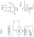
- the stand-alone control circuit is designated by the reference number 18 in Figure 3. Said circuit is able to receive both the signal indicating the intention to proceed with filling, which is activated by the control member 16' and the signal indicating that the pre-set maximum level of LPG in the tank has been reached, which is activated by the sensor 9.
- the control circuit 18 consequently controls the solenoid 19 of the solenoid valve ( Figure 3). More precisely, when the control member 16 is brought into the position C, generating the signal indicating the intention to proceed with filling, the circuit 18 excites the solenoid 19 that consequently controls opening of the valve 12, (which is normally in the closing condition). Once the valve 12 is opened, supply of LPG into the tank is possible. However, said condition is maintained only provided that the level of LPG in the tank does not exceed the pre-set maximum level. When said maximum level is reached, the sensor 9 closes, and the control circuit 18 consequently causes de-excitation of the solenoid 19.
- Figure 4 illustrates, by way of example, a possible circuit diagram that enables the above result to be obtained.
- the operating logic illustrated above is also represented in the block diagram of Figure 2.
- the first block illustrates activation of the filling mode, obtained by displacing the control member 16 into the position of selection C.
- the circuit checks, in the second block, whether the pre-set maximum level, corresponding to 80% of the tank capacity, has been reached. Until said maximum level is reached, filling continues. When, instead, said limit is reached, the circuit causes deactivation of the solenoid of the solenoid valve 12, with consequent arrest of supply.
- Figure 5 illustrates, as already indicated, a preferred embodiment of the solenoid valve 12.
- the valve comprises a valve body 20 having a tubular connection 21 that is inserted in a fluid-tight way within an opening 10 of the plate 11 for closing the tank.
- the body 20 moreover has a flange 22 provided with holes for engagement of screws for fixing the valve to the plate 11.
- the valve 12 comprises a main open/close element 23 consisting of a conical body made of elastomeric material co-operating with an annular valve seat defined by one end of the axial passage 24 of the tubular connection 21.
- the axial passage 24 gives out into an enlarged cylindrical chamber 25, in which there is slidably mounted a piston 26, which carries, at one of its ends, the main open/close element 23.
- Said open/close element has a ring-shaped body fitted around an axial protuberance 27 of the piston 26.
- the piston 26 is slidably mounted in a fluid-tight way, with the aid of an annular gasket 28 mounted in one of its external circumferential grooves, inside the enlarged cylindrical chamber 25.
- the piston 26 On account of the different transverse dimensions of the axial passage 24 and of the cavity 25, the piston 26 has differentiated end surfaces.
- the bottom end surface (as viewed in Figure 5) faces a chamber 29, which is able to communicate, via a pilot hole 30, with a chamber 31, which in turn communicates with the cavity of the tank via holes 32 made in the valve body 20.
- Said valve body moreover has radial passages 33 for setting the axial passage 24 in communication with the cavity of the tank in the condition of opening of the main open/close element 23.
- the piston 26 is also traversed by an axial passage 34, which is able to set the two chambers facing the opposite ends of the piston in communication via a non-return valve consisting of a ball 35 pushed by a spring 36.
- the spring 36 will rest on a disk 37, which is received in the axial passage of the piston 26 and is pressed by a further helical spring 38.
- the pilot hole 30 is controlled by an auxiliary open/close element 39, which is associated to the mobile core 40 of an electromagnet, which includes the solenoid 19 (illustrated in the diagrams of Figures 3 and 4) and a spring 41, which tends to press the auxiliary open/close element 39 into the condition for closing of the pilot hole 30.
- the auxiliary open/close element 39 is in its condition for closing the pilot hole 30 and the main open/close element 23 is in turn in its position for closing communication between the axial passage 24 and the holes 33 for supply of LPG into the tank.
- the liquid will flow through the axial passage 34 of the piston 26, opening the non-return valve consisting of the ball 35 and flowing into the chamber 29 under the piston 26.
- the piston 26 will be subject at both of its ends to the same filling pressure.
- the end surface of the piston 26 facing the chamber 29 has an extension greater than the end surface of the piston facing the axial passage 24, the piston will remain closed.
- the spring 38 does not have any significant function in maintaining the main open/close element 23 in its closing position, notwithstanding the pressure exerted thereon by the liquid supplied, in so far as it is the opposite and differentiated sections of the piston that guarantee said condition.
- the spring 41, associated to the solenoid 19 need to ensure the condition of closing of the main open/close element 23.
- the open/close element 23 can be servo-actuated in opening by excitation of the solenoid 19. Said excitation in fact causes displacement of the mobile core 40 downwards (as viewed in Figure 5) and consequently displacement of the auxiliary open/close element 39 into its position for opening the pilot hole 30.
- the chamber 29 is set in communication, via the holes 32, with the environment of the tank so that the piston 26 is displaced from its closing position.
- the piston As soon as the piston is displaced, the entire top surface of the piston is subjected to the pressure of the fluid supplied, so that the main open/close element 23 is displaced decidedly into the position of complete opening, in which it enables the LPG arriving through the axial passage 24 to flow into the tank through the radial holes 33 of the valve body 20.
- the auxiliary open/close element 39 returns to its closing condition, so that the pressure in the chamber 29 can rise again, which brings the piston 26 back again into its closing position, also thanks to the contribution of the spring 38.
- the differentiated sections at the two ends of the piston guarantee maintenance of said condition, for the same reasons as those mentioned above.
- the valve according to the invention uses the solenoid only for controlling an auxiliary open/close element, which in turn controls a pilot hole 30. Consequently, the spring 41 of the solenoid can have a relatively low load in so far as it is not necessary to overcome the force due to the pressure of supply of LPG. Since the load of the spring 41 is low, also the force of attraction that must be generated by the solenoid 19 is low, which enables a considerable saving in terms of energy.
Landscapes
- Engineering & Computer Science (AREA)
- Mechanical Engineering (AREA)
- General Engineering & Computer Science (AREA)
- Transportation (AREA)
- Chemical & Material Sciences (AREA)
- Combustion & Propulsion (AREA)
- Life Sciences & Earth Sciences (AREA)
- Sustainable Energy (AREA)
- Sustainable Development (AREA)
- Filling Or Discharging Of Gas Storage Vessels (AREA)
- Output Control And Ontrol Of Special Type Engine (AREA)
- Check Valves (AREA)
- Electrical Discharge Machining, Electrochemical Machining, And Combined Machining (AREA)
Abstract
Description
- a tank for LPG, having an inlet mouth for introduction of LPG;
- a valve that controls communication through said inlet mouth;
- sensor means for detecting the level of LPG in the tank; and
- means for controlling closing of said valve when the sensor means signal that a pre-set maximum level of LPG in the tank has been reached,
- said valve is a normally closed valve that can be driven in opening by excitation of a solenoid;
- said sensor means are pre-arranged to emit a first electrical signal when said pre-set maximum level of LPG in the tank is reached;
- the system further comprises:
- a control member, which can be operated manually, for generating a second electrical signal indicating the intention to proceed with filling the tank; and
- a control circuit, which is independent of the
circuit on board the motor vehicle and is hence active
even when the engine of the motor vehicle is turned
off, said control circuit being pre-arranged for
receiving said first signal and said second signal and
being connected to the solenoid of said valve, so as
to:
- excite the solenoid of the valve in order to control opening thereof when said circuit receives said second signal indicating activation of the mode of filling and until said first signal indicating that the pre-set maximum level of LPG in the tank has been reached is received; and
- de-excite said solenoid to control closing of the valve, when said first signal indicating that the pre-set maximum level of LPG in the tank has been reached is received.
- Figure 1 is a schematic view of a system for controlling filling of a tank with LPG according to the invention;
- Figure 2 is a block diagram that illustrates the operating logic of the system;
- Figure 3 illustrates a block diagram of the system, including the stand-alone control circuit;
- Figure 4 illustrates a diagram of an example of embodiment of the control circuit; and
- Figure 5 is a cross-sectional view, at an enlarged scale, of a preferred embodiment of the solenoid valve forming part of the system according to the invention.
Claims (8)
- A system for controlling filling of a motor-vehicle tank with LPG, comprising:said system being characterized in that:a tank for LPG (1), having an inlet mouth for introduction of LPG;a valve (12) that controls communication through said inlet mouth;sensor means (9) for detecting the level of LPG in the tank; andmeans for controlling closing of said valve (12) when the sensor means (9) signal that a pre-set maximum level of LPG in the tank has been reached,said valve (12) is a normally closed valve that can be driven in opening by excitation of a solenoid (19);said sensor means (9) are pre-arranged to emit a first electrical signal when said pre-set maximum level of LPG in the tank is reached;the system further comprises:a control member (16), which can be operated manually, for generating a second electrical signal indicating the intention to proceed with filling the tank (1); anda control circuit (18), which is independent of the circuit on board the motor vehicle (i.e., a stand-alone circuit) so as to be active even when the vehicle engine is turned off, said stand-alone circuit being pre-arranged for receiving said first signal and said second signal, and connected to the solenoid (19) of said valve (12), so as to:excite the solenoid (19) of the valve, in order to control opening thereof, when said circuit receives said second signal indicating activation of the modality of supply and until said first signal indicating that the pre-set maximum level of LPG in the tank has been reached is received, andde-excite said solenoid (19) to control closing of the valve (12), when said first signal indicating that the pre-set maximum level of LPG in the tank has been reached is received.
- The system according to Claim 1, characterized in that said sensor means consist of a magnetically activated electrical sensor, arranged on a supporting structure (7), which is fixed with respect to the structure of the tank and co-operates with at least one permanent magnet carried by a floating body (8) guided with respect to said fixed structure (7).
- The system according to Claim 2, characterized in that said sensor is a reed relay (9), set at the end of a series of reed relays pre-arranged on one and the same supporting structure (7) and co-operating with said permanent magnet of said floating body (8) to provide signalling of the level of LPG in the tank.
- The system according to Claim 1, characterized in that said manually operated control member (16) is a selector member, provided on the dashboard on board the motor vehicle, which enables selection of the mode for filling the tank with LPG.
- The system according to Claim 1, characterized in that said control circuit is integrated in the structure of said valve (12).
- The system according to Claim 1, characterized in that said valve (12) can be driven in opening by means of a servo device that can be activated by excitation of said solenoid (19).
- A solenoid valve for controlling communication through the inlet mouth for filling a tank (1) with LPG, comprising: a main open/close element (23), which is normally kept in a closing position by a piston (26) with differentiated opposite sections, both of which are substantially subjected to the pressure of supply of the LPG; an auxiliary open/close element (39), which is normally kept, by elastic means (41), in a closing position of a pilot hole (30); and a solenoid (19) for displacing the auxiliary open/close element (39) into an opening position of said pilot hole (30), into which there is discharged a chamber facing said piston (26) to enable displacement of the piston towards the opening position of said main open/close element (23).
- The solenoid valve according to Claim 7 characterized in that said piston (26) is traversed by an axial passage (34), in which there is set a non-return valve (35), which prevents flow of LPG in the direction of the valve inlet.
Applications Claiming Priority (2)
| Application Number | Priority Date | Filing Date | Title |
|---|---|---|---|
| ITTO20030761 ITTO20030761A1 (en) | 2003-09-30 | 2003-09-30 | SYSTEM FOR FILLING OF A TANK |
| ITTO20030761 | 2003-09-30 |
Publications (3)
| Publication Number | Publication Date |
|---|---|
| EP1520744A2 true EP1520744A2 (en) | 2005-04-06 |
| EP1520744A3 EP1520744A3 (en) | 2005-04-13 |
| EP1520744B1 EP1520744B1 (en) | 2006-07-05 |
Family
ID=34308160
Family Applications (1)
| Application Number | Title | Priority Date | Filing Date |
|---|---|---|---|
| EP20040022157 Expired - Lifetime EP1520744B1 (en) | 2003-09-30 | 2004-09-17 | Solenoid valve for controlling filling of a motor vehicle tank with LPG and filling system comprising such a valve |
Country Status (8)
| Country | Link |
|---|---|
| US (1) | US20050263186A1 (en) |
| EP (1) | EP1520744B1 (en) |
| AT (1) | ATE332248T1 (en) |
| AU (1) | AU2004214523A1 (en) |
| CA (1) | CA2482103A1 (en) |
| DE (1) | DE602004001428T2 (en) |
| ES (1) | ES2268557T3 (en) |
| IT (1) | ITTO20030761A1 (en) |
Cited By (1)
| Publication number | Priority date | Publication date | Assignee | Title |
|---|---|---|---|---|
| ITBO20090510A1 (en) * | 2009-07-31 | 2011-02-01 | Bakel Werner Hans Joachim Van | CONTAINER WITH MANUAL PUMP FOR THE INTRODUCTION OF A DOSED FLUID IN THE G.P.L. TANK |
Families Citing this family (8)
| Publication number | Priority date | Publication date | Assignee | Title |
|---|---|---|---|---|
| US20080209622A1 (en) * | 2007-03-01 | 2008-09-04 | Wood Kurt E | Electronic toilet tank monitor utilizing a bistable latching solenoid control circuit |
| KR101664508B1 (en) * | 2011-12-12 | 2016-10-11 | 현대자동차주식회사 | Apparatus and method for reducing the temperature of a cylinder using LPG vaporization latent heat |
| CN104736370A (en) * | 2012-09-25 | 2015-06-24 | 沃尔沃建筑设备公司 | An arrangement, a method and a computer program for controlling filling of a tank |
| KR101371761B1 (en) * | 2012-12-26 | 2014-03-07 | 기아자동차(주) | Lpg bombe apparatus |
| US9850119B2 (en) * | 2016-03-16 | 2017-12-26 | Blend-Rite Industries, Inc. | Automatic truck tank fill system |
| CN114651164A (en) * | 2019-12-19 | 2022-06-21 | Vega格里沙贝两合公司 | Measuring device for detecting a filling or limit level of a filling material in a container and method for filling or emptying a container with a filling material |
| EP3951238A1 (en) * | 2020-08-07 | 2022-02-09 | AEREA S.p.A. | Dual tank pneumatic valve |
| KR102772595B1 (en) * | 2022-08-12 | 2025-02-26 | 홍영일 | Refrigerant automatic charging system using single float |
Family Cites Families (15)
| Publication number | Priority date | Publication date | Assignee | Title |
|---|---|---|---|---|
| US2824278A (en) * | 1954-10-01 | 1958-02-18 | Honeywell Regulator Co | Liquid level sensing apparatus |
| US3446474A (en) * | 1967-07-31 | 1969-05-27 | Borg Warner | Hydraulic pilot valve |
| US4334410A (en) * | 1980-12-03 | 1982-06-15 | Huguette Drumare | Tank designed to contain a liquefied gas |
| EP0086154B1 (en) * | 1982-02-05 | 1988-11-09 | Compagnie Des Gaz De Petrole Primagaz | Liquid container and working method thereof |
| US4447743A (en) * | 1982-04-28 | 1984-05-08 | The United States Of America As Represented By The United States Department Of Energy | High pressure liquid level monitor |
| DE3717341A1 (en) * | 1987-05-22 | 1988-12-08 | Daimler Benz Ag | VALVE ARRANGEMENT WITH MAIN SWITCHING VALVE AND PILOT VALVE |
| US5197710A (en) * | 1991-05-30 | 1993-03-30 | Lloyd G. Wass | Crash proof solenoid controlled valve for natural gas powered vehicles |
| DE4331568C2 (en) * | 1993-09-16 | 2001-10-18 | Buerkert Gmbh | Pilot operated valve for motor vehicle fuel systems |
| DE19727923B4 (en) * | 1997-07-01 | 2006-08-03 | Siemens Ag | tank system |
| US6435210B1 (en) * | 1998-03-31 | 2002-08-20 | Continental Teves Ag & Co. Ohg | Electromagnetic valve |
| US6328275B1 (en) * | 2000-02-04 | 2001-12-11 | Husco International, Inc. | Bidirectional pilot operated control valve |
| DE10020000B4 (en) * | 2000-04-22 | 2012-03-22 | Audi Ag | Device on a fuel tank for motor vehicles |
| US6658933B2 (en) * | 2001-06-22 | 2003-12-09 | Clesse Industries | Fill-level indicator for a liquefied-petroleum-gas tank |
| US6571626B1 (en) * | 2001-10-11 | 2003-06-03 | Walbro Corporation | Fuel level sensor |
| JP2003120352A (en) * | 2001-10-16 | 2003-04-23 | Aisan Ind Co Ltd | Engine fuel switching method and apparatus |
-
2003
- 2003-09-30 IT ITTO20030761 patent/ITTO20030761A1/en unknown
-
2004
- 2004-09-17 ES ES04022157T patent/ES2268557T3/en not_active Expired - Lifetime
- 2004-09-17 EP EP20040022157 patent/EP1520744B1/en not_active Expired - Lifetime
- 2004-09-17 DE DE200460001428 patent/DE602004001428T2/en not_active Expired - Fee Related
- 2004-09-17 AT AT04022157T patent/ATE332248T1/en not_active IP Right Cessation
- 2004-09-21 CA CA 2482103 patent/CA2482103A1/en not_active Abandoned
- 2004-09-22 AU AU2004214523A patent/AU2004214523A1/en not_active Abandoned
- 2004-09-30 US US10/953,577 patent/US20050263186A1/en not_active Abandoned
Cited By (1)
| Publication number | Priority date | Publication date | Assignee | Title |
|---|---|---|---|---|
| ITBO20090510A1 (en) * | 2009-07-31 | 2011-02-01 | Bakel Werner Hans Joachim Van | CONTAINER WITH MANUAL PUMP FOR THE INTRODUCTION OF A DOSED FLUID IN THE G.P.L. TANK |
Also Published As
| Publication number | Publication date |
|---|---|
| EP1520744B1 (en) | 2006-07-05 |
| CA2482103A1 (en) | 2005-03-30 |
| DE602004001428D1 (en) | 2006-08-17 |
| US20050263186A1 (en) | 2005-12-01 |
| ATE332248T1 (en) | 2006-07-15 |
| EP1520744A3 (en) | 2005-04-13 |
| ITTO20030761A1 (en) | 2005-04-01 |
| DE602004001428T2 (en) | 2006-11-09 |
| ES2268557T3 (en) | 2007-03-16 |
| AU2004214523A1 (en) | 2005-04-14 |
Similar Documents
| Publication | Publication Date | Title |
|---|---|---|
| KR100495961B1 (en) | Solenoid valve | |
| EP1520744B1 (en) | Solenoid valve for controlling filling of a motor vehicle tank with LPG and filling system comprising such a valve | |
| US6253802B1 (en) | Electromechanically controlled refueling valve | |
| US20060065324A1 (en) | Valve assembly and refueling sensor | |
| KR102542982B1 (en) | Methods for Functional Testing of Electromechanical Level Monitoring Devices | |
| JP2006027595A (en) | Automotive fuel system | |
| JPH08100768A (en) | Pump device, in particular pump device for a tank system of an internal combustion engine | |
| KR20230070029A (en) | Tank device for storage of gaseous medium with valve device | |
| US20090014275A1 (en) | Clutch System with a Hydraulically Actuated Clutch Device | |
| US6685280B1 (en) | Vehicle braking system and vehicle braking device | |
| JP2001206092A (en) | Driving force distribution device | |
| JPH0681933B2 (en) | Fuel supply pump device | |
| AU2011284430A1 (en) | Relief valve and fuel vapor valve assembly | |
| EP1107084A2 (en) | By-pass solenoid with integral check valve | |
| EP1008791B1 (en) | Solenoid valve | |
| CA2016420A1 (en) | Solenoid valve | |
| EP0079715B1 (en) | Combined pressure relief and unloader valve | |
| JP3332577B2 (en) | Cushion unit | |
| JPS6346755Y2 (en) | ||
| JPH08210135A (en) | Cooling device of automobile engine | |
| JPH0642624A (en) | Automatic transmission controller | |
| KR100250266B1 (en) | Automotive Fuel Spill Prevention System | |
| KR100224192B1 (en) | Apparatus of supplying oil for an automobile | |
| JPH05340410A (en) | Hydraulic control system | |
| JP4067882B2 (en) | Solenoid valve |
Legal Events
| Date | Code | Title | Description |
|---|---|---|---|
| PUAI | Public reference made under article 153(3) epc to a published international application that has entered the european phase |
Free format text: ORIGINAL CODE: 0009012 |
|
| PUAL | Search report despatched |
Free format text: ORIGINAL CODE: 0009013 |
|
| AK | Designated contracting states |
Kind code of ref document: A2 Designated state(s): AT BE BG CH CY CZ DE DK EE ES FI FR GB GR HU IE IT LI LU MC NL PL PT RO SE SI SK TR |
|
| AX | Request for extension of the european patent |
Extension state: AL HR LT LV MK |
|
| AK | Designated contracting states |
Kind code of ref document: A3 Designated state(s): AT BE BG CH CY CZ DE DK EE ES FI FR GB GR HU IE IT LI LU MC NL PL PT RO SE SI SK TR |
|
| AX | Request for extension of the european patent |
Extension state: AL HR LT LV MK |
|
| 17P | Request for examination filed |
Effective date: 20050623 |
|
| GRAP | Despatch of communication of intention to grant a patent |
Free format text: ORIGINAL CODE: EPIDOSNIGR1 |
|
| AKX | Designation fees paid |
Designated state(s): AT BE BG CH CY CZ DE DK EE ES FI FR GB GR HU IE IT LI LU MC NL PL PT RO SE SI SK TR |
|
| RTI1 | Title (correction) |
Free format text: SOLENOID VALVE FOR CONTROLLING FILLING OF A MOTOR VEHICLE TANK WITH LPG AND FILLING SYSTEM COMPRISING SUCH A VALVE |
|
| GRAS | Grant fee paid |
Free format text: ORIGINAL CODE: EPIDOSNIGR3 |
|
| GRAA | (expected) grant |
Free format text: ORIGINAL CODE: 0009210 |
|
| AK | Designated contracting states |
Kind code of ref document: B1 Designated state(s): AT BE BG CH CY CZ DE DK EE ES FI FR GB GR HU IE IT LI LU MC NL PL PT RO SE SI SK TR |
|
| PG25 | Lapsed in a contracting state [announced via postgrant information from national office to epo] |
Ref country code: CZ Free format text: LAPSE BECAUSE OF FAILURE TO SUBMIT A TRANSLATION OF THE DESCRIPTION OR TO PAY THE FEE WITHIN THE PRESCRIBED TIME-LIMIT Effective date: 20060705 Ref country code: CH Free format text: LAPSE BECAUSE OF FAILURE TO SUBMIT A TRANSLATION OF THE DESCRIPTION OR TO PAY THE FEE WITHIN THE PRESCRIBED TIME-LIMIT Effective date: 20060705 Ref country code: FI Free format text: LAPSE BECAUSE OF FAILURE TO SUBMIT A TRANSLATION OF THE DESCRIPTION OR TO PAY THE FEE WITHIN THE PRESCRIBED TIME-LIMIT Effective date: 20060705 Ref country code: AT Free format text: LAPSE BECAUSE OF FAILURE TO SUBMIT A TRANSLATION OF THE DESCRIPTION OR TO PAY THE FEE WITHIN THE PRESCRIBED TIME-LIMIT Effective date: 20060705 Ref country code: SK Free format text: LAPSE BECAUSE OF FAILURE TO SUBMIT A TRANSLATION OF THE DESCRIPTION OR TO PAY THE FEE WITHIN THE PRESCRIBED TIME-LIMIT Effective date: 20060705 Ref country code: SI Free format text: LAPSE BECAUSE OF FAILURE TO SUBMIT A TRANSLATION OF THE DESCRIPTION OR TO PAY THE FEE WITHIN THE PRESCRIBED TIME-LIMIT Effective date: 20060705 Ref country code: LI Free format text: LAPSE BECAUSE OF FAILURE TO SUBMIT A TRANSLATION OF THE DESCRIPTION OR TO PAY THE FEE WITHIN THE PRESCRIBED TIME-LIMIT Effective date: 20060705 Ref country code: BE Free format text: LAPSE BECAUSE OF FAILURE TO SUBMIT A TRANSLATION OF THE DESCRIPTION OR TO PAY THE FEE WITHIN THE PRESCRIBED TIME-LIMIT Effective date: 20060705 Ref country code: RO Free format text: LAPSE BECAUSE OF FAILURE TO SUBMIT A TRANSLATION OF THE DESCRIPTION OR TO PAY THE FEE WITHIN THE PRESCRIBED TIME-LIMIT Effective date: 20060705 Ref country code: PL Free format text: LAPSE BECAUSE OF FAILURE TO SUBMIT A TRANSLATION OF THE DESCRIPTION OR TO PAY THE FEE WITHIN THE PRESCRIBED TIME-LIMIT Effective date: 20060705 |
|
| REG | Reference to a national code |
Ref country code: GB Ref legal event code: FG4D |
|
| REG | Reference to a national code |
Ref country code: SE Ref legal event code: TRGR |
|
| REG | Reference to a national code |
Ref country code: CH Ref legal event code: EP |
|
| REG | Reference to a national code |
Ref country code: IE Ref legal event code: FG4D |
|
| REF | Corresponds to: |
Ref document number: 602004001428 Country of ref document: DE Date of ref document: 20060817 Kind code of ref document: P |
|
| PGFP | Annual fee paid to national office [announced via postgrant information from national office to epo] |
Ref country code: FR Payment date: 20060908 Year of fee payment: 3 |
|
| PGFP | Annual fee paid to national office [announced via postgrant information from national office to epo] |
Ref country code: DE Payment date: 20060914 Year of fee payment: 3 |
|
| PG25 | Lapsed in a contracting state [announced via postgrant information from national office to epo] |
Ref country code: IE Free format text: LAPSE BECAUSE OF NON-PAYMENT OF DUE FEES Effective date: 20060918 |
|
| PG25 | Lapsed in a contracting state [announced via postgrant information from national office to epo] |
Ref country code: MC Free format text: LAPSE BECAUSE OF NON-PAYMENT OF DUE FEES Effective date: 20060930 |
|
| PG25 | Lapsed in a contracting state [announced via postgrant information from national office to epo] |
Ref country code: DK Free format text: LAPSE BECAUSE OF FAILURE TO SUBMIT A TRANSLATION OF THE DESCRIPTION OR TO PAY THE FEE WITHIN THE PRESCRIBED TIME-LIMIT Effective date: 20061005 Ref country code: BG Free format text: LAPSE BECAUSE OF FAILURE TO SUBMIT A TRANSLATION OF THE DESCRIPTION OR TO PAY THE FEE WITHIN THE PRESCRIBED TIME-LIMIT Effective date: 20061005 |
|
| PGFP | Annual fee paid to national office [announced via postgrant information from national office to epo] |
Ref country code: ES Payment date: 20061023 Year of fee payment: 3 |
|
| PG25 | Lapsed in a contracting state [announced via postgrant information from national office to epo] |
Ref country code: PT Free format text: LAPSE BECAUSE OF FAILURE TO SUBMIT A TRANSLATION OF THE DESCRIPTION OR TO PAY THE FEE WITHIN THE PRESCRIBED TIME-LIMIT Effective date: 20061205 |
|
| ET | Fr: translation filed | ||
| REG | Reference to a national code |
Ref country code: ES Ref legal event code: FG2A Ref document number: 2268557 Country of ref document: ES Kind code of ref document: T3 |
|
| PLBE | No opposition filed within time limit |
Free format text: ORIGINAL CODE: 0009261 |
|
| STAA | Information on the status of an ep patent application or granted ep patent |
Free format text: STATUS: NO OPPOSITION FILED WITHIN TIME LIMIT |
|
| 26N | No opposition filed |
Effective date: 20070410 |
|
| PGFP | Annual fee paid to national office [announced via postgrant information from national office to epo] |
Ref country code: SE Payment date: 20060906 Year of fee payment: 3 |
|
| PG25 | Lapsed in a contracting state [announced via postgrant information from national office to epo] |
Ref country code: GR Free format text: LAPSE BECAUSE OF FAILURE TO SUBMIT A TRANSLATION OF THE DESCRIPTION OR TO PAY THE FEE WITHIN THE PRESCRIBED TIME-LIMIT Effective date: 20061006 Ref country code: SE Free format text: LAPSE BECAUSE OF NON-PAYMENT OF DUE FEES Effective date: 20070918 |
|
| EUG | Se: european patent has lapsed | ||
| PG25 | Lapsed in a contracting state [announced via postgrant information from national office to epo] |
Ref country code: EE Free format text: LAPSE BECAUSE OF FAILURE TO SUBMIT A TRANSLATION OF THE DESCRIPTION OR TO PAY THE FEE WITHIN THE PRESCRIBED TIME-LIMIT Effective date: 20060705 |
|
| PG25 | Lapsed in a contracting state [announced via postgrant information from national office to epo] |
Ref country code: LU Free format text: LAPSE BECAUSE OF NON-PAYMENT OF DUE FEES Effective date: 20060917 Ref country code: DE Free format text: LAPSE BECAUSE OF NON-PAYMENT OF DUE FEES Effective date: 20080401 Ref country code: TR Free format text: LAPSE BECAUSE OF FAILURE TO SUBMIT A TRANSLATION OF THE DESCRIPTION OR TO PAY THE FEE WITHIN THE PRESCRIBED TIME-LIMIT Effective date: 20060705 Ref country code: HU Free format text: LAPSE BECAUSE OF FAILURE TO SUBMIT A TRANSLATION OF THE DESCRIPTION OR TO PAY THE FEE WITHIN THE PRESCRIBED TIME-LIMIT Effective date: 20070106 |
|
| REG | Reference to a national code |
Ref country code: FR Ref legal event code: ST Effective date: 20080531 |
|
| PG25 | Lapsed in a contracting state [announced via postgrant information from national office to epo] |
Ref country code: FR Free format text: LAPSE BECAUSE OF NON-PAYMENT OF DUE FEES Effective date: 20071001 |
|
| PG25 | Lapsed in a contracting state [announced via postgrant information from national office to epo] |
Ref country code: CY Free format text: LAPSE BECAUSE OF FAILURE TO SUBMIT A TRANSLATION OF THE DESCRIPTION OR TO PAY THE FEE WITHIN THE PRESCRIBED TIME-LIMIT Effective date: 20060705 |
|
| REG | Reference to a national code |
Ref country code: ES Ref legal event code: FD2A Effective date: 20070918 |
|
| PG25 | Lapsed in a contracting state [announced via postgrant information from national office to epo] |
Ref country code: ES Free format text: LAPSE BECAUSE OF NON-PAYMENT OF DUE FEES Effective date: 20070918 |
|
| GBPC | Gb: european patent ceased through non-payment of renewal fee |
Effective date: 20080917 |
|
| PG25 | Lapsed in a contracting state [announced via postgrant information from national office to epo] |
Ref country code: NL Free format text: LAPSE BECAUSE OF NON-PAYMENT OF DUE FEES Effective date: 20090401 |
|
| NLV4 | Nl: lapsed or anulled due to non-payment of the annual fee |
Effective date: 20090401 |
|
| PG25 | Lapsed in a contracting state [announced via postgrant information from national office to epo] |
Ref country code: IT Free format text: LAPSE BECAUSE OF NON-PAYMENT OF DUE FEES Effective date: 20080917 |
|
| PGFP | Annual fee paid to national office [announced via postgrant information from national office to epo] |
Ref country code: IT Payment date: 20070930 Year of fee payment: 4 |
|
| PG25 | Lapsed in a contracting state [announced via postgrant information from national office to epo] |
Ref country code: GB Free format text: LAPSE BECAUSE OF NON-PAYMENT OF DUE FEES Effective date: 20080917 |