EP1520765B1 - Güterzugwagen mit Entladevorrichtung, insbesondere für den Transport von Schüttgütern - Google Patents
Güterzugwagen mit Entladevorrichtung, insbesondere für den Transport von Schüttgütern Download PDFInfo
- Publication number
- EP1520765B1 EP1520765B1 EP04023293A EP04023293A EP1520765B1 EP 1520765 B1 EP1520765 B1 EP 1520765B1 EP 04023293 A EP04023293 A EP 04023293A EP 04023293 A EP04023293 A EP 04023293A EP 1520765 B1 EP1520765 B1 EP 1520765B1
- Authority
- EP
- European Patent Office
- Prior art keywords
- goods train
- train wagon
- drive unit
- wagon
- frame construction
- Prior art date
- Legal status (The legal status is an assumption and is not a legal conclusion. Google has not performed a legal analysis and makes no representation as to the accuracy of the status listed.)
- Expired - Lifetime
Links
- 239000000463 material Substances 0.000 title description 12
- 239000013590 bulk material Substances 0.000 claims abstract description 27
- 238000010276 construction Methods 0.000 claims description 13
- 230000010355 oscillation Effects 0.000 claims description 3
- 238000007599 discharging Methods 0.000 claims 2
- 239000002245 particle Substances 0.000 description 4
- 230000000284 resting effect Effects 0.000 description 3
- 230000035939 shock Effects 0.000 description 3
- 230000005284 excitation Effects 0.000 description 2
- 230000003139 buffering effect Effects 0.000 description 1
- 230000003137 locomotive effect Effects 0.000 description 1
- 238000012423 maintenance Methods 0.000 description 1
- 238000000034 method Methods 0.000 description 1
- 239000004576 sand Substances 0.000 description 1
- 239000000725 suspension Substances 0.000 description 1
- 239000002023 wood Substances 0.000 description 1
Images



Classifications
-
- B—PERFORMING OPERATIONS; TRANSPORTING
- B61—RAILWAYS
- B61D—BODY DETAILS OR KINDS OF RAILWAY VEHICLES
- B61D7/00—Hopper cars
- B61D7/14—Adaptations of hopper elements to railways
- B61D7/32—Means for assisting charge or discharge
Definitions
- the invention relates to a freight train with a drive, a base and an associated structure with a bottom and lateral boundary walls for receiving bulk material, the structure at least one closable opening for loading and / or unloading and the bottom at least one relative to the horizontal in Direction of the closable opening inclined inclined plane, which is formed by a recorded in a frame construction plate and is displaceable by means of a plate attached to the drive unit in a Virbrationsschwingung.
- Such freight cars are from the DE 818 770 C as well as the DE 826 266 C known, wherein the arrangement of the vibration generator is provided below the container bottom.
- freight cars for example, from the DE-OS-2007268 and the EP 0 941 907 known.
- This freight car bulk goods or granular products in bulk, such. As wood and sawdust, which are used in particular in the paper industry transported.
- the unloading is generally carried out by pushing out the load by means of vehicles such as wheel loaders provided with an ejector in the form of an ejector or backhoe with which the load can be discharged across the sides, with the unloading vehicle on the ground outside the transport vehicle is moved.
- the ejector or the unloading vehicle itself causes damage to the transport vehicle and in particular to structures such as poles, supports or hinges of side flaps, which are arranged, for example, on a wagon instead of walls and open for discharge.
- the inflatable pad consists of a tight bag or bellows of flexible material, which occupies the volume of the vehicle or the cargo space when inflated.
- the unloading device covers the floor of the vehicle and forms an over the entire height extending wall opposite the discharge opening. It has been found that with such unloading complete emptying of the transport vehicle is not guaranteed, especially in the corners of the structure.
- the disadvantages of the prior art is that no freight car for the transport of bulk materials is known, with which the bulk materials can be discharged completely and easily.
- the invention is in view of this prior art, the object of avoiding the disadvantages mentioned to provide a transport vehicle with an unloading, with the complete and easy emptying of the transport vehicle is guaranteed in the shortest possible period.
- Such a freight train car is advantageously simple, fast and without the aid of further aids completely dischargeable, for example, by being moved to an unloading station, the closable openings for loading and unloading is opened and the drive unit is put into operation.
- the inclined plane is put into vibration oscillations, which are preferably sufficiently strong to dissolve the cohesion of the individual particles of the bulk material among one another. Due to the vibrational movements of the inclined plane, the particles of the bulk material located on the inclined plane lose their grip on each other and begin to slide along the inclined plane.
- the inclined plane is formed by a plate received in a frame construction.
- the frame structure may be formed by interconnected profile elements.
- Such a construction advantageously offers a simple possibility for realizing an inclined plane.
- the inclined plane can be made flexible in terms of their dimensions and can be used with advantage in already existing freight train as a retrofit kit. Such an inclined plane is also robust, inexpensive and can be produced by simple means.
- the oblique plane forming plate may be received in the frame structure such that it forms a dense for the respective bulk material transport space together with the other limits of the freight train wagon.
- the bottom of the goods train wagon has at least one inclined plane inclined relative to the horizontal in the direction of the closable opening.
- the frame construction of the inclined plane is fixed to the floor of the goods train wagon. This advantageously achieves that the inclined planes can not move in the structure by mass forces exerted by the bulk materials or by movements during the journey of the freight train wagon. This also brings advantages in a possible empty transport of a freight car according to the invention.
- the present invention further provides that the inclined plane is displaceable with the frame structure by the drive unit in vibrations.
- the frame can be made in two parts with an upper and a lower part.
- the lower part of the frame is expediently fixed to the bottom of the freight train wagon.
- the upper part of the frame, which together with the plate forms the inclined plane is fastened to the lower part of the frame by means of suitable elastic connecting means.
- the inclined plane in this embodiment vibrates substantially equally in all regions. Thus, even in corners and edges stuck bulk residues can be relaxed by the vibrations exerted by the inclined plane.
- the bottom of the goods wagon has several inclined planes.
- freight cars with arranged at different points of the car loading and / or unloading can be easily and quickly discharged by providing multiple slated planes. It is advantageously possible to retrofit freight cars with several discharge openings with several inclined planes.
- a further embodiment of the invention provides that the bottom of the goods wagon has a plurality of inclined planes inclined with respect to the horizontal, which are inclined alternately to the left and to the right side of the freight wagon.
- the bottom of the goods wagon has a plurality of inclined planes inclined with respect to the horizontal, which are inclined alternately to the left and to the right side of the freight wagon.
- the loading and / or unloading openings on both sides of the carriage it is advantageously made possible that the available opening cross-section, through which the bulk materials are unloaded, is as large as possible. This minimizes the time required for the unloading process.
- the bulk goods receiving and further conveying or further processing devices are arranged on both sides of a rail track, in which the bulk goods are introduced directly from the freight car.
- Another embodiment of the invention has a floor with two inclined planes inclined from the center in the direction of the left and right sides of the goods wagon.
- a further embodiment of the invention provides that the drive unit is mounted on the plate.
- the vibration movements of the drive unit can be initiated directly into the plate of the inclined plane.
- the plate is expediently dimensioned such that its strength is sufficient to carry the weight exerted by the bulk materials, the plate, however, can be excited by the drive unit to swing, so that the vibration movements of the plate in the form of shock waves in the Bulk materials are introduced.
- a further embodiment of the invention provides that the drive unit is a drive generating a vibration by means of an imbalance.
- Such drives are known from the prior art.
- the drive unit may, for example, be a vibrator which is fastened with a base component to the unit to be vibrated. Vibrations of the vibrator are generated by a mass moved relative to the base member. The masses can be moved both translationally and rotationally. The inertial forces exerted by the moving mass on the base member are introduced by the fixed or elastic attachment of the base member with the element to be vibrated in this.
- Such vibrators are technically simple and robust and inexpensive to produce.
- the drive units and the plates are coordinated so that they perform a vibration in a resonant frequency.
- the dimensions of the plate for example, the plate thickness, the mass and the vibration frequency of the drive unit can be achieved that the unit formed by the drive unit and plate oscillates in a resonant frequency.
- the plate oscillates advantageously by a minimal excitation with a maximum amplitude. In this way, the strongest possible shock waves are introduced into the bulk material while applying the lowest possible energy.
- the drive unit is advantageously electrically driven.
- the drive unit can be supplied directly from the electrical network of the train, from the locomotive pulling the respective freight train or from another external electrical energy source.
- the power supply of the drive unit takes place via an intermediate control and operating unit.
- control and operating unit is not attached to the freight train itself, but externally at an unloading station.
- the drive unit is connected, for example, with a cable with a plug-in contact attached to a suitable location on the freight train car.
- this plug contact is connected, for example via another cable with the externally attached to the unloading control and operating unit for driving the inclined plane.
- a further embodiment of the invention provides that the drive unit is placed on the bulk material facing side of the plate and is protected by a housing. Furthermore, it is provided that the housing is advantageously attached to the plate. Through the housing, the drive unit is advantageously protected from damage by the bulk material.
- the housing may be releasably secured to the plate, which together with the arrangement of the drive unit on the bulk material side facing the plate good accessibility and ease of maintenance of the drive unit is achieved.
- the housing can be advantageously designed such that its outer contour does not hinder a discharge of the bulk material.
- the housing may for example be wedge-shaped in the flow direction of the bulk material and / or with rounded corners and edges, whereby the bulk material of the bulk material is little impeded and a movement of the individual particles of the bulk material is conveyed past the housing.
- a further embodiment of the present invention provides that the structure has frontal and lateral boundary walls, wherein one or both lateral boundary walls are provided with at least one closable opening for loading or unloading, which is closed by at least one opening element to be opened.
- the opening may further extend over the entire sidewall area and continue to be closed by at least two corresponding through-going flap doors.
- a further embodiment of the invention provides with advantage that the boundary walls of the structure are formed beveled in their lower region in each case in the direction of the inclined planes. This avoids that bulk material could settle on corners and edges in the interior of the structure, resulting in incomplete or difficult unloading of goods wagons.
- the entire interior of the structure is designed such that each of the boundary walls and the bottom form coordinated inclined planes, which favor emptying of the bulk material.
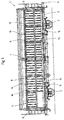
- the in Fig. 1 It has a biaxial drive 2, which is connected in not described in detail known manner with a base frame 3, which consists of an approximately at the level of the buffer 4 arranged welded profile frame, which vertical loads that absorbs buffering forces and tensioning forces and the vertical and lateral forces resulting from the barrel.
- the base frame 3 carries a box-shaped structure 5 of a framework with end walls 6, side wall posts 7 and the connecting upper side members 8, wherein a bottom 9 rests on the base frame 3 and serves to receive the load. Since the end walls 6 are closed, is to Loading and unloading provided to form a loading and unloading by the entire side wall area is to be opened, in addition, a closable roof opening may be provided.
- the opening of the side wall portion takes place in the freight car 1 by the measure that the side walls of at least two, in the embodiment shown in the drawing of four continuously opening folding doors 10, 11, 12 and 13 are formed, on each side of the freight car 1.
- This is therefore equipped with a total of eight folding doors, in the closed position in Fig. 1 the drawing and in the open position in Fig. 2 the drawing are shown schematically.
- Each lower flap door 11 and 13 extends in the longitudinal direction at a height which is slightly less than half the height of the side wall portion of the body 5 and is either directly on the level of the discharge edge of the bottom 9 or 9 in the illustrated embodiment below the bottom an axis 14 pivotally mounted.
- each lower flap 11 or 13 the associated upper flap 10 and 12 is arranged in the same vertical plane, which corresponds to the lower flap and which together form the longitudinal side wall of the goods wagon 1.
- the upper flaps 10 and 12 extend in the longitudinal direction over the upper half of the vehicle body and are pivotally mounted about an axis 15 which is arranged on the level of the upper longitudinal member 8 of the goods wagon 1.
- each longitudinal side wall four folding doors of the type described are provided in the described embodiment to make a simple and variable loading and unloading on both sides on a very long vehicle of more than 12 m in length, including the side wall posts 7 for mounting and suspension of the flap doors in the middle of the car.
- the folding doors 10, 11, 12 and 13 can be additionally held in their middle by a respective center holder 16 on the base frame 3 and 5 structure.
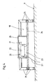
- the inclined planes 17 each have two inclined sides 18 and 19.
- the sides 18 in this case has a slight angle of inclination relative to the horizontal, while the sides 19 are strongly inclined with respect to the horizontal.
- the pages 19 can also parallel to the flap doors 10, 11, 12, and 13 (ie, substantially vertical).
- a drive unit 20 is mounted on the flat inclined sides 18 .
- the drive unit 20 may be, for example, an electric motor 22 provided with an imbalance 21, which is fastened with a frame 23 on the flat side 18.
- the drive unit 20 is expediently covered with a housing 24.
- the flat sides 18 of the inclined planes 17 are formed by a frame 25 and a plate 26 received in this frame 25.
- the frame 25 is preferably welded together from individual profile elements, for example made of U-profiles.
- the plate 26 is received in the U-shaped groove of these profile elements.
- the drive units 20 are connected by means of a wiring 27 with an attached at a suitable location on the freight car 1 plug-in contact 28.
- the plug contact 28 is connected during unloading of the freight car 1 with a control and operating unit, not shown.
- the control and operating unit is stationary at a suitable location of an unloading station, for example in a server shed or the like. In this way, it is not necessary to equip each goods train with an operating unit, which would be exposed there much harder loads than at the unloading station.
- a freight train For unloading a freight train is driven to an unloading station.
- the wagons of the train located in an unloading position are connected to the control and operating unit of the unloading station, and the folding doors 10, 11, 12 and 13 are opened.
- the drive units 20 are actuated by means of the control and operating unit.
- the electric motors 22 begin to rotate and generate due to the imbalance 21 strong, vibrating vibrations that are introduced via the plates 26 as shock waves in the bulk material. Relationships between the individual particles of the bulk material are dissolved.
- the bulk material begins to slide along the inclined planes 17.
- the plates 26 are vibrated until the entire bulk material is emptied. Due to the inclination of the sides 19 it is achieved that the folding doors 10, 11, 12 and 13 are easy to close after the emptying of the wagon.
Landscapes
- Engineering & Computer Science (AREA)
- Transportation (AREA)
- Mechanical Engineering (AREA)
- Loading Or Unloading Of Vehicles (AREA)
- Ship Loading And Unloading (AREA)
Priority Applications (1)
| Application Number | Priority Date | Filing Date | Title |
|---|---|---|---|
| PL04023293T PL1520765T3 (pl) | 2003-10-02 | 2004-09-30 | Wagon towarowy z urządzeniem wyładunkowym, zwłaszcza do transportu materiałów sypkich |
Applications Claiming Priority (2)
| Application Number | Priority Date | Filing Date | Title |
|---|---|---|---|
| DE20315403U DE20315403U1 (de) | 2003-10-02 | 2003-10-02 | Güterzugwagen mit Entladevorrichtung, insbesondere für den Transport von Schüttgütern |
| DE20315403U | 2003-10-02 |
Publications (2)
| Publication Number | Publication Date |
|---|---|
| EP1520765A1 EP1520765A1 (de) | 2005-04-06 |
| EP1520765B1 true EP1520765B1 (de) | 2010-04-21 |
Family
ID=29724301
Family Applications (1)
| Application Number | Title | Priority Date | Filing Date |
|---|---|---|---|
| EP04023293A Expired - Lifetime EP1520765B1 (de) | 2003-10-02 | 2004-09-30 | Güterzugwagen mit Entladevorrichtung, insbesondere für den Transport von Schüttgütern |
Country Status (4)
| Country | Link |
|---|---|
| EP (1) | EP1520765B1 (pl) |
| AT (1) | ATE465060T1 (pl) |
| DE (2) | DE20315403U1 (pl) |
| PL (1) | PL1520765T3 (pl) |
Families Citing this family (1)
| Publication number | Priority date | Publication date | Assignee | Title |
|---|---|---|---|---|
| RU182496U1 (ru) * | 2018-02-01 | 2018-08-21 | Акционерное общество "Научно-внедренческий центр "Вагоны" (АО "НВЦ "Вагоны") | Четырехосный вагон-хоппер |
Family Cites Families (4)
| Publication number | Priority date | Publication date | Assignee | Title |
|---|---|---|---|---|
| DE818770C (de) * | 1949-12-28 | 1951-10-29 | Rudolf Ahrens | Fahrbarer Selbstentlader |
| DE826266C (de) * | 1950-02-15 | 1951-12-27 | Rudolf Ahrens | Fahrbarer Selbstentlader |
| DE862120C (de) * | 1951-02-23 | 1953-01-08 | Losenhausenwerk Duesseldorfer | Vorrichtung zum Abladen von Schuettgut aus Fahrzeugen |
| EP0941907B1 (de) * | 1997-12-13 | 2003-01-22 | Railtrans S.A. | Güterzugwagen, insbesondere für den Transport von Schüttgütern |
-
2003
- 2003-10-02 DE DE20315403U patent/DE20315403U1/de not_active Expired - Lifetime
-
2004
- 2004-09-30 AT AT04023293T patent/ATE465060T1/de active
- 2004-09-30 PL PL04023293T patent/PL1520765T3/pl unknown
- 2004-09-30 EP EP04023293A patent/EP1520765B1/de not_active Expired - Lifetime
- 2004-09-30 DE DE502004011067T patent/DE502004011067D1/de not_active Expired - Lifetime
Also Published As
| Publication number | Publication date |
|---|---|
| DE20315403U1 (de) | 2003-12-04 |
| EP1520765A1 (de) | 2005-04-06 |
| DE502004011067D1 (de) | 2010-06-02 |
| ATE465060T1 (de) | 2010-05-15 |
| PL1520765T3 (pl) | 2010-12-31 |
Similar Documents
| Publication | Publication Date | Title |
|---|---|---|
| DD261618A5 (de) | Gleisverfahrbarer schuettgutverladewagen | |
| DE19623940B4 (de) | Speicherwagen zur Speicherung von Schüttgut | |
| EP1690809A2 (de) | Behälter und Entleervorrichtung | |
| EP1184248B1 (de) | Schüttgutverladewagen | |
| DE69209278T2 (de) | Niederbordwagen aus zusammenhängenden einheiten | |
| EP1520765B1 (de) | Güterzugwagen mit Entladevorrichtung, insbesondere für den Transport von Schüttgütern | |
| CA3027095C (en) | LONGITUDINAL SLIDING DOOR INTENDED FOR A HOPPER WAGON | |
| US20190001997A1 (en) | Longitudinal gate hopper car without partitions | |
| EP2789519B1 (de) | Vorrichtung zur Materialförderung im Gleisbau | |
| DE69007216T2 (de) | Eisenbahnwagen für den Transport von Schutt. | |
| CN218319520U (zh) | 集装箱翻箱机以及铁路运输的集装箱装料卸料系统 | |
| DE3720652A1 (de) | Fahrzeugaufbau fuer die hochentleerung von ladegut | |
| DE862120C (de) | Vorrichtung zum Abladen von Schuettgut aus Fahrzeugen | |
| DE818770C (de) | Fahrbarer Selbstentlader | |
| US3094227A (en) | Compaction bodies | |
| EP1929091B1 (de) | Schüttgutverladewagen | |
| WO2008022779A2 (de) | Modulares transportsystem mit mulden und waggons für schüttgut | |
| EP0587063B1 (de) | Lastfahrzeug mit Schüttgut-Container | |
| EP4360983B1 (de) | Verfahren zum durchführen von arbeiten an einer schienenfahrbahn | |
| RU9439U1 (ru) | Пункт механизированной загрузки угля в пассажирские вагоны | |
| DE1200858B (de) | Foerderwagenzug fuer Schuettgut | |
| DE971736C (de) | Vorrichtung zum Entleeren von offenen Eisenbahngueterwagen | |
| DE595552C (de) | Wagenentleerer mit Erschuetterungsvorrichtung | |
| DE202005002765U1 (de) | Güterzugwagen | |
| US3331517A (en) | Bottom dump car |
Legal Events
| Date | Code | Title | Description |
|---|---|---|---|
| PUAI | Public reference made under article 153(3) epc to a published international application that has entered the european phase |
Free format text: ORIGINAL CODE: 0009012 |
|
| AK | Designated contracting states |
Kind code of ref document: A1 Designated state(s): AT BE BG CH CY CZ DE DK EE ES FI FR GB GR HU IE IT LI LU MC NL PL PT RO SE SI SK TR |
|
| AX | Request for extension of the european patent |
Extension state: AL HR LT LV MK |
|
| 17P | Request for examination filed |
Effective date: 20051006 |
|
| AKX | Designation fees paid |
Designated state(s): AT BE BG CH CY CZ DE DK EE ES FI FR GB GR HU IE IT LI LU MC NL PL PT RO SE SI SK TR |
|
| 17Q | First examination report despatched |
Effective date: 20060719 |
|
| RAP1 | Party data changed (applicant data changed or rights of an application transferred) |
Owner name: VTG FRANCE SAS |
|
| GRAP | Despatch of communication of intention to grant a patent |
Free format text: ORIGINAL CODE: EPIDOSNIGR1 |
|
| GRAS | Grant fee paid |
Free format text: ORIGINAL CODE: EPIDOSNIGR3 |
|
| GRAA | (expected) grant |
Free format text: ORIGINAL CODE: 0009210 |
|
| AK | Designated contracting states |
Kind code of ref document: B1 Designated state(s): AT BE BG CH CY CZ DE DK EE ES FI FR GB GR HU IE IT LI LU MC NL PL PT RO SE SI SK TR |
|
| REG | Reference to a national code |
Ref country code: GB Ref legal event code: FG4D Free format text: NOT ENGLISH |
|
| REG | Reference to a national code |
Ref country code: CH Ref legal event code: EP |
|
| REG | Reference to a national code |
Ref country code: IE Ref legal event code: FG4D Free format text: LANGUAGE OF EP DOCUMENT: GERMAN |
|
| REF | Corresponds to: |
Ref document number: 502004011067 Country of ref document: DE Date of ref document: 20100602 Kind code of ref document: P |
|
| REG | Reference to a national code |
Ref country code: NL Ref legal event code: VDEP Effective date: 20100421 |
|
| PG25 | Lapsed in a contracting state [announced via postgrant information from national office to epo] |
Ref country code: NL Free format text: LAPSE BECAUSE OF FAILURE TO SUBMIT A TRANSLATION OF THE DESCRIPTION OR TO PAY THE FEE WITHIN THE PRESCRIBED TIME-LIMIT Effective date: 20100421 Ref country code: ES Free format text: LAPSE BECAUSE OF FAILURE TO SUBMIT A TRANSLATION OF THE DESCRIPTION OR TO PAY THE FEE WITHIN THE PRESCRIBED TIME-LIMIT Effective date: 20100801 Ref country code: SE Free format text: LAPSE BECAUSE OF FAILURE TO SUBMIT A TRANSLATION OF THE DESCRIPTION OR TO PAY THE FEE WITHIN THE PRESCRIBED TIME-LIMIT Effective date: 20100421 |
|
| REG | Reference to a national code |
Ref country code: IE Ref legal event code: FD4D |
|
| PG25 | Lapsed in a contracting state [announced via postgrant information from national office to epo] |
Ref country code: SI Free format text: LAPSE BECAUSE OF FAILURE TO SUBMIT A TRANSLATION OF THE DESCRIPTION OR TO PAY THE FEE WITHIN THE PRESCRIBED TIME-LIMIT Effective date: 20100421 Ref country code: FI Free format text: LAPSE BECAUSE OF FAILURE TO SUBMIT A TRANSLATION OF THE DESCRIPTION OR TO PAY THE FEE WITHIN THE PRESCRIBED TIME-LIMIT Effective date: 20100421 |
|
| PGFP | Annual fee paid to national office [announced via postgrant information from national office to epo] |
Ref country code: AT Payment date: 20100914 Year of fee payment: 7 Ref country code: FR Payment date: 20101005 Year of fee payment: 7 |
|
| PG25 | Lapsed in a contracting state [announced via postgrant information from national office to epo] |
Ref country code: GR Free format text: LAPSE BECAUSE OF FAILURE TO SUBMIT A TRANSLATION OF THE DESCRIPTION OR TO PAY THE FEE WITHIN THE PRESCRIBED TIME-LIMIT Effective date: 20100722 Ref country code: CY Free format text: LAPSE BECAUSE OF FAILURE TO SUBMIT A TRANSLATION OF THE DESCRIPTION OR TO PAY THE FEE WITHIN THE PRESCRIBED TIME-LIMIT Effective date: 20100421 |
|
| REG | Reference to a national code |
Ref country code: PL Ref legal event code: T3 |
|
| PG25 | Lapsed in a contracting state [announced via postgrant information from national office to epo] |
Ref country code: IE Free format text: LAPSE BECAUSE OF FAILURE TO SUBMIT A TRANSLATION OF THE DESCRIPTION OR TO PAY THE FEE WITHIN THE PRESCRIBED TIME-LIMIT Effective date: 20100421 Ref country code: PT Free format text: LAPSE BECAUSE OF FAILURE TO SUBMIT A TRANSLATION OF THE DESCRIPTION OR TO PAY THE FEE WITHIN THE PRESCRIBED TIME-LIMIT Effective date: 20100823 Ref country code: EE Free format text: LAPSE BECAUSE OF FAILURE TO SUBMIT A TRANSLATION OF THE DESCRIPTION OR TO PAY THE FEE WITHIN THE PRESCRIBED TIME-LIMIT Effective date: 20100421 Ref country code: DK Free format text: LAPSE BECAUSE OF FAILURE TO SUBMIT A TRANSLATION OF THE DESCRIPTION OR TO PAY THE FEE WITHIN THE PRESCRIBED TIME-LIMIT Effective date: 20100421 |
|
| PLBE | No opposition filed within time limit |
Free format text: ORIGINAL CODE: 0009261 |
|
| STAA | Information on the status of an ep patent application or granted ep patent |
Free format text: STATUS: NO OPPOSITION FILED WITHIN TIME LIMIT |
|
| PG25 | Lapsed in a contracting state [announced via postgrant information from national office to epo] |
Ref country code: CZ Free format text: LAPSE BECAUSE OF FAILURE TO SUBMIT A TRANSLATION OF THE DESCRIPTION OR TO PAY THE FEE WITHIN THE PRESCRIBED TIME-LIMIT Effective date: 20100421 Ref country code: SK Free format text: LAPSE BECAUSE OF FAILURE TO SUBMIT A TRANSLATION OF THE DESCRIPTION OR TO PAY THE FEE WITHIN THE PRESCRIBED TIME-LIMIT Effective date: 20100421 Ref country code: RO Free format text: LAPSE BECAUSE OF FAILURE TO SUBMIT A TRANSLATION OF THE DESCRIPTION OR TO PAY THE FEE WITHIN THE PRESCRIBED TIME-LIMIT Effective date: 20100421 |
|
| PGFP | Annual fee paid to national office [announced via postgrant information from national office to epo] |
Ref country code: DE Payment date: 20100922 Year of fee payment: 7 Ref country code: PL Payment date: 20100825 Year of fee payment: 7 |
|
| 26N | No opposition filed |
Effective date: 20110124 |
|
| BERE | Be: lapsed |
Owner name: VTG FRANCE SAS Effective date: 20100930 |
|
| PG25 | Lapsed in a contracting state [announced via postgrant information from national office to epo] |
Ref country code: IT Free format text: LAPSE BECAUSE OF FAILURE TO SUBMIT A TRANSLATION OF THE DESCRIPTION OR TO PAY THE FEE WITHIN THE PRESCRIBED TIME-LIMIT Effective date: 20100421 |
|
| PG25 | Lapsed in a contracting state [announced via postgrant information from national office to epo] |
Ref country code: MC Free format text: LAPSE BECAUSE OF NON-PAYMENT OF DUE FEES Effective date: 20100930 |
|
| REG | Reference to a national code |
Ref country code: CH Ref legal event code: PL |
|
| GBPC | Gb: european patent ceased through non-payment of renewal fee |
Effective date: 20100930 |
|
| PG25 | Lapsed in a contracting state [announced via postgrant information from national office to epo] |
Ref country code: LI Free format text: LAPSE BECAUSE OF NON-PAYMENT OF DUE FEES Effective date: 20100930 Ref country code: BE Free format text: LAPSE BECAUSE OF NON-PAYMENT OF DUE FEES Effective date: 20100930 Ref country code: CH Free format text: LAPSE BECAUSE OF NON-PAYMENT OF DUE FEES Effective date: 20100930 |
|
| PG25 | Lapsed in a contracting state [announced via postgrant information from national office to epo] |
Ref country code: GB Free format text: LAPSE BECAUSE OF NON-PAYMENT OF DUE FEES Effective date: 20100930 |
|
| REG | Reference to a national code |
Ref country code: FR Ref legal event code: ST Effective date: 20120531 |
|
| REG | Reference to a national code |
Ref country code: DE Ref legal event code: R119 Ref document number: 502004011067 Country of ref document: DE Effective date: 20120403 |
|
| PG25 | Lapsed in a contracting state [announced via postgrant information from national office to epo] |
Ref country code: DE Free format text: LAPSE BECAUSE OF NON-PAYMENT OF DUE FEES Effective date: 20120403 |
|
| PG25 | Lapsed in a contracting state [announced via postgrant information from national office to epo] |
Ref country code: FR Free format text: LAPSE BECAUSE OF NON-PAYMENT OF DUE FEES Effective date: 20110930 |
|
| PG25 | Lapsed in a contracting state [announced via postgrant information from national office to epo] |
Ref country code: LU Free format text: LAPSE BECAUSE OF NON-PAYMENT OF DUE FEES Effective date: 20100930 Ref country code: BG Free format text: LAPSE BECAUSE OF FAILURE TO SUBMIT A TRANSLATION OF THE DESCRIPTION OR TO PAY THE FEE WITHIN THE PRESCRIBED TIME-LIMIT Effective date: 20100421 Ref country code: HU Free format text: LAPSE BECAUSE OF FAILURE TO SUBMIT A TRANSLATION OF THE DESCRIPTION OR TO PAY THE FEE WITHIN THE PRESCRIBED TIME-LIMIT Effective date: 20101022 |
|
| PG25 | Lapsed in a contracting state [announced via postgrant information from national office to epo] |
Ref country code: PL Free format text: LAPSE BECAUSE OF NON-PAYMENT OF DUE FEES Effective date: 20110930 Ref country code: TR Free format text: LAPSE BECAUSE OF FAILURE TO SUBMIT A TRANSLATION OF THE DESCRIPTION OR TO PAY THE FEE WITHIN THE PRESCRIBED TIME-LIMIT Effective date: 20100421 |
|
| REG | Reference to a national code |
Ref country code: AT Ref legal event code: MM01 Ref document number: 465060 Country of ref document: AT Kind code of ref document: T Effective date: 20110930 |
|
| REG | Reference to a national code |
Ref country code: PL Ref legal event code: LAPE |
|
| PG25 | Lapsed in a contracting state [announced via postgrant information from national office to epo] |
Ref country code: AT Free format text: LAPSE BECAUSE OF NON-PAYMENT OF DUE FEES Effective date: 20110930 |
|
| PG25 | Lapsed in a contracting state [announced via postgrant information from national office to epo] |
Ref country code: BG Free format text: LAPSE BECAUSE OF FAILURE TO SUBMIT A TRANSLATION OF THE DESCRIPTION OR TO PAY THE FEE WITHIN THE PRESCRIBED TIME-LIMIT Effective date: 20100721 |