EP1520771A1 - Aerodynamisch ausgebildetes Verkleidungsteil für die Unterseite eines Kraftfahrzeuges, insbesondere Personenwagens - Google Patents
Aerodynamisch ausgebildetes Verkleidungsteil für die Unterseite eines Kraftfahrzeuges, insbesondere Personenwagens Download PDFInfo
- Publication number
- EP1520771A1 EP1520771A1 EP04014300A EP04014300A EP1520771A1 EP 1520771 A1 EP1520771 A1 EP 1520771A1 EP 04014300 A EP04014300 A EP 04014300A EP 04014300 A EP04014300 A EP 04014300A EP 1520771 A1 EP1520771 A1 EP 1520771A1
- Authority
- EP
- European Patent Office
- Prior art keywords
- air guide
- guide element
- part according
- covering part
- receiving opening
- Prior art date
- Legal status (The legal status is an assumption and is not a legal conclusion. Google has not performed a legal analysis and makes no representation as to the accuracy of the status listed.)
- Granted
Links
Images




Classifications
-
- B—PERFORMING OPERATIONS; TRANSPORTING
- B60—VEHICLES IN GENERAL
- B60K—ARRANGEMENT OR MOUNTING OF PROPULSION UNITS OR OF TRANSMISSIONS IN VEHICLES; ARRANGEMENT OR MOUNTING OF PLURAL DIVERSE PRIME-MOVERS IN VEHICLES; AUXILIARY DRIVES FOR VEHICLES; INSTRUMENTATION OR DASHBOARDS FOR VEHICLES; ARRANGEMENTS IN CONNECTION WITH COOLING, AIR INTAKE, GAS EXHAUST OR FUEL SUPPLY OF PROPULSION UNITS IN VEHICLES
- B60K11/00—Arrangement in connection with cooling of propulsion units
- B60K11/08—Air inlets for cooling; Shutters or blinds therefor
-
- B—PERFORMING OPERATIONS; TRANSPORTING
- B62—LAND VEHICLES FOR TRAVELLING OTHERWISE THAN ON RAILS
- B62D—MOTOR VEHICLES; TRAILERS
- B62D35/00—Vehicle bodies characterised by streamlining
- B62D35/02—Streamlining the undersurfaces
-
- B—PERFORMING OPERATIONS; TRANSPORTING
- B60—VEHICLES IN GENERAL
- B60K—ARRANGEMENT OR MOUNTING OF PROPULSION UNITS OR OF TRANSMISSIONS IN VEHICLES; ARRANGEMENT OR MOUNTING OF PLURAL DIVERSE PRIME-MOVERS IN VEHICLES; AUXILIARY DRIVES FOR VEHICLES; INSTRUMENTATION OR DASHBOARDS FOR VEHICLES; ARRANGEMENTS IN CONNECTION WITH COOLING, AIR INTAKE, GAS EXHAUST OR FUEL SUPPLY OF PROPULSION UNITS IN VEHICLES
- B60K11/00—Arrangement in connection with cooling of propulsion units
- B60K11/06—Arrangement in connection with cooling of propulsion units with air cooling
-
- Y—GENERAL TAGGING OF NEW TECHNOLOGICAL DEVELOPMENTS; GENERAL TAGGING OF CROSS-SECTIONAL TECHNOLOGIES SPANNING OVER SEVERAL SECTIONS OF THE IPC; TECHNICAL SUBJECTS COVERED BY FORMER USPC CROSS-REFERENCE ART COLLECTIONS [XRACs] AND DIGESTS
- Y02—TECHNOLOGIES OR APPLICATIONS FOR MITIGATION OR ADAPTATION AGAINST CLIMATE CHANGE
- Y02T—CLIMATE CHANGE MITIGATION TECHNOLOGIES RELATED TO TRANSPORTATION
- Y02T10/00—Road transport of goods or passengers
- Y02T10/80—Technologies aiming to reduce greenhouse gasses emissions common to all road transportation technologies
- Y02T10/82—Elements for improving aerodynamics
-
- Y—GENERAL TAGGING OF NEW TECHNOLOGICAL DEVELOPMENTS; GENERAL TAGGING OF CROSS-SECTIONAL TECHNOLOGIES SPANNING OVER SEVERAL SECTIONS OF THE IPC; TECHNICAL SUBJECTS COVERED BY FORMER USPC CROSS-REFERENCE ART COLLECTIONS [XRACs] AND DIGESTS
- Y02—TECHNOLOGIES OR APPLICATIONS FOR MITIGATION OR ADAPTATION AGAINST CLIMATE CHANGE
- Y02T—CLIMATE CHANGE MITIGATION TECHNOLOGIES RELATED TO TRANSPORTATION
- Y02T10/00—Road transport of goods or passengers
- Y02T10/80—Technologies aiming to reduce greenhouse gasses emissions common to all road transportation technologies
- Y02T10/88—Optimized components or subsystems, e.g. lighting, actively controlled glasses
Definitions
- the invention relates to an aerodynamically designed trim part for the Underside of a motor vehicle, especially a passenger car with an adjacent an inlet opening arranged air guide element, wherein in driving a Partial air flow passing between the cowling and the roadway Cooling air through the inlet opening and the at least partially above the Covering parts lying air guide element to an overlying unit and / or chassis part is passed.
- Such a trim part is known from DE 37 16 701 A1.
- the air guide element by a adjacent the inlet opening arranged scoop-shaped holding element formed on the one hand on Covering part and on the other hand attached to the overlying gear housing.
- This double attachment requires a relatively large installation effort and is very time-consuming.
- the object of the invention is to provide a provided with an air guide element Fairing part for the underside of a motor vehicle to develop so that the Attachment between the cowling and the air guide simplified becomes.
- a formed by a passenger car, not shown in detail motor vehicle is on its underside provided with an aerodynamically formed trim part 1.
- the cowling 1 is formed to a roadway completely smooth surface and in in a known manner kept in position on the superstructure. It covers preferably the entire vehicle underside and can be formed one or more parts be. In the exemplary embodiment, this is preferably by an injection molded part made of plastic formed cowling 1 formed in several parts.
- Fig. 1 shows a rear-side portion 2 of the trim part 1, which tapers in the embodiment opposite to the direction of travel F towards the rear.
- the cowling 1 has on its underside locally at least one inlet opening 3 and an air guide element 4, wherein during operation of the motor vehicle, a partial air flow A of the between the cowling 1 and the roadway cooling air flowing through the inlet opening 3 of the air guide element 4 via a provided on the air guide element 4 outlet opening 5 is passed to an overlying unit and / or chassis part and this cools.
- cooling air is guided to a Deutschenachsgetriebe not shown in detail.
- the air guide element 4 is from the side facing the lane B of the Covering parts 1, that is from the bottom into a receiving opening 6 of the Paneling parts 1 used (insertion position C) and on the edge acting Sliding snap-in connections 7 releasably connected to the trim part 1.
- the Inlet opening 3 is gem.
- the sliding snap-in connections 7 comprise on opposite longitudinal sides 11, 12 formed of the air guide element 4 locking elements 13, with the edge side of the Receiving opening 6 of the covering part 1 provided holding portions 14th interacting latching.
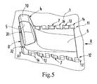
- Each locking element 13 of the air guide element 4 is in mounting position D with two spaced-apart holding portions 14 of the Covering parts 1 in operative connection (Fig. 5).
- the receiving opening 6 is gem.
- Fig. 1 laterally offset to a longitudinal center plane E-E of the motor vehicle arranged on the cowling 1 and has in plan view seen an approximately quadrangular basic form.
- the two mutually parallel sides 15, 16 are in Vehicle transverse direction aligned and form the front end and the rear end the receiving opening 6.
- the oblique sides 17, 18 of the receiving opening. 6 extend in the longitudinal direction of the motor vehicle.
- Figure 1 tapers conical receiving opening 6 towards the rear of the vehicle.
- the receiving opening 6 could also be rectangular or the like. Be formed.
- the Adjacent retaining tabs 20, 21 have a height offset to each other.
- the Retaining tabs 20 extend flush with the fairing part 1, whereas the Retaining tabs 21 are turned off the cowling 1 upwards.
- Adjacent to that front edge 22 of the receiving opening 6 is on both longitudinal sides 17, 18 each one in the plane of the trim part 1 extending retaining tab 20 and adjacent to the rear edge 23 of the receiving opening 6 each one higher lying arranged Retaining tab 21 formed (Fig. 2).
- each four arranged one behind the other locking elements 13 is provided (Fig. 3). It can also more or less locking elements 13 per longitudinal side on Air guide element 4 may be arranged.
- Each locking element 13 has seen in the direction of insertion R obliquely upwards protruding insertion portion 27, an adjoining first support portion 28th and a subsequent second support portion 29.
- the second support section 29 runs approximately flush with the contour of the trim part 1, whereas the first Abstützabites 28 is turned off at the top.
- the locking elements 13 each have a longitudinal extent L1 and a width B1 (FIG. 3).
- the assembly of the air guide element 4 is carried out as follows: First, the Air guide element 4 from below into the receiving opening 6 of the trim part. 1 used. The insertion position C is reached when all the insertion tongues 27 of Air guide element 4 protrude into the region of the recesses 19. At the support subsequent displacement of the air guide element 4 in the insertion direction R. First, the insertion tongues 27 at the top of the holding sections from. By further longitudinal displacement of the air guide element 4 in the direction of insertion R be formed the locking connections 7 and the air guide element 4 takes its Assembly position D on.
Landscapes
- Engineering & Computer Science (AREA)
- Chemical & Material Sciences (AREA)
- Combustion & Propulsion (AREA)
- Transportation (AREA)
- Mechanical Engineering (AREA)
- Cooling, Air Intake And Gas Exhaust, And Fuel Tank Arrangements In Propulsion Units (AREA)
- Road Paving Structures (AREA)
Abstract
Description
Es zeigt
- Fig. 1
- eine perspektivische Ansicht von schräg hinten auf einen Teilbereich eines Verkleidungsteiles für die Unterseite eines Kraftfahrzeuges mit dem Luftführungselement,
- Fig. 2
- eine perspektivische Ansicht auf das Verkleidungsteil mit der Aufnahmeöffnung,
- Fig. 3
- eine perspektivische Ansicht auf das Luftführungselement,
- Fig. 4
- eine perspektivische Ansicht auf das Luftführungselement mit der Aufnahmeöffnung und dem eingesetzten Luftführungselement in einer Einführstellung,
- Fig. 5
- eine perspektivische Ansicht ähnlich Fig. 4, jedoch in Montagestellung des Luftführungselementes,
- Fig. 6
- einen Schnitt nach der Linie VI-VI der Fig. 5,
- Fig. 7
- einen vertikalen Längsschnitt durch das Verkleidungsteil und das eingesetzte Luftführungselement in Montagestellung D.
Das Verkleidungsteil 1 weist an seiner Unterseite örtlich zumindest eine Eintrittsöffnung 3 sowie ein Luftführungselement 4 auf, wobei im Fahrbetrieb des Kraftfahrzeuges ein Teilluftstrom A der zwischen dem Verkleidungsteil 1 und der Fahrbahn hindurchströmenden Kühlluft durch die Eintrittsöffnung 3 des Luftführungselementes 4 über eine am Luftführungselement 4 vorgesehene Austrittsöffnung 5 zu einem darüber liegenden Aggregat und/oder Fahrwerksteil geleitet wird und dieses kühlt. Im Ausführungsbeispiel wird Kühlluft zu einem nicht näher gezeigten Hinterachsgetriebe geführt.
Claims (16)
- Aerodynamisch ausgebildetes Verkleidungsteil für die Unterseite eines Kraftfahrzeuges, insbesondere Personenwagens mit einem benachbart einer Eintrittsöffnung angeordneten Luftführungselement, wobei im Fahrbetrieb ein Teilluftstrom der zwischen dem Verkleidungsteil und der Fahrbahn hindurchströmenden Kühlluft durch die Eintrittsöffnung und das zumindest bereichsweise oberhalb des Verkleidungsteiles liegende Luftführungselement zu einem darüber liegenden Aggregat und/oder Fahrwerksteil geleitet wird, dadurch gekennzeichnet, dass das Luftführungselement (4) in eine Aufnahmeöffnung (6) des Verkleidungsteiles (1) eingesetzt und über Schiebe-Rastverbindungen (7) mit dem Verkleidungsteil (1) verbunden ist.
- Verkleidungsteil nach Anspruch 1, dadurch gekennzeichnet, dass die Eintrittsöffnung (3) am Luftführungselement (4) ausgebildet ist.
- Verkleidungsteil nach den Ansprüchen 1 und 2 dadurch gekennzeichnet, dass das Luftführungselement (4) einen plattenförmigen Grundkörper (8) mit einem der Eintrittsöffnung (3) vorgelagerten Anströmkanal (9) aufweist, an den sich ein nach oben ragender Luftführungskanal (10) anschließt, der mit einer Austrittsöffnung (5) versehen ist.
- Verkleidungsteil nach Anspruch nach Anspruch 1, dadurch gekennzeichnet, dass die Schiebe-Rastverbindungen (7) an gegenüberliegenden Seiten (11, 12) des Luftführungselementes (4) ausgebildete Rastelemente (13) umfassen, die mit randseitig an der Aufnahmeöffnung (6) des Verkleidungsteiles (1) vorgesehenen Halteabschnitten (14) verrastend zusammenwirken.
- Verkleidungsteil nach Anspruch 4, dadurch gekennzeichnet, dass jedes Rastelement (13) des Luftführungselementes (4) mit zwei beabstandet angeordneten Halteabschnitten (14) des Verkleidungsteiles (1) in Wirkverbindung steht.
- Verkleidungsteil nach Anspruch 1, dadurch gekennzeichnet, dass das Luftführungselement (4) von der der Fahrbahn zugekehrten Seite (B) des Verkleidungsteiles (1) her in die Aufnahmeöffnung (6) eingesetzt ist.
- Verkleidungsteil nach Anspruch 1, dadurch gekennzeichnet, dass die Aufnahmeöffnung (6) in der Draufsicht gesehen eine viereckige, vorzugsweise rechteckige oder trapezförmige Grundform aufweist.
- Verkleidungsteil nach einem der vorangegangenen Ansprüche, dadurch gekennzeichnet, dass sich die beiden längeren gegenüberliegenden Seiten (17, 18) der Aufnahmeöffnung (6) in Fahrzeuglängsrichtung des Kraftfahrzeuges erstrecken.
- Verkleidungsteil nach einem der vorangegangenen Ansprüche, dadurch gekennzeichnet, dass sich die Aufnahmeöffnung (6) konisch verjüngt.
- Verkleidungsteil nach einem der vorangegangenen Ansprüche, dadurch gekennzeichnet, dass an gegenüberliegenden Seiten (17, 18) der Aufnahmeöffnung (6) jeweils mehrere mit Abstand zueinander angeordnete Halteabschnitte (14) ausgebildet sind, wobei zwischen zwei angrenzenden Halteabschnitten (14) jeweils eine - in der Draufsicht gesehen - etwa U-förmige Ausnehmung (19) ausgebildet ist.
- Verkleidungsteil nach Anspruch 10, dadurch gekennzeichnet, dass die entfernt vom vorderen und hinteren Rand der Aufnahmeöffnung (6) vorgesehenen Halteabschnitte (14) jeweils durch stufenförmig angeordnete hintereinanderliegende Haltelaschen (20, 21) gebildet werden, wobei die Haltelaschen (20) außenhautbündig mit dem Verkleidungsteil (1) verlaufen, wogegen die Haltelaschen (21) vom Verkleidungsteil (1) nach oben hin abgestellt sind.
- Verkleidungsteil nach einem der vorangegangenen Ansprüche, dadurch gekennzeichnet, dass an beiden gegenüberliegenden Längsseiten (11, 12) des Luftführungselementes (4) jeweils mehrere mit Abstand zueinander angeordnete nach außen ragende Halteelemente (13) angeformt sind, wobei zwischen zwei angrenzenden Halteelementen (13) jeweils eine in der Draufsicht gesehen etwa U-förmige Aussparung (26) vorgesehen ist.
- Verkleidungsteil nach einem der vorangegangenen Ansprüche, dadurch gekennzeichnet, dass jedes Rastelement (13) einen schräg nach oben ragenden vorderen Einführabschnitt (27), einen daran anschließenden ersten Abstützabschnitt (28) und einen nachfolgenden zweiten Stützabschnitt (29) aufweist, wobei der zweite Abstützabschnitt (29) bündig mit dem Verkleidungsteil (1) verläuft.
- Verkleidungsteil nach einem der vorangegangenen Ansprüche, dadurch gekennzeichnet, dass bei eingesetztem Luftführungselement (4) die Unterseite des ersten Abstützabschnitts (28) an der Oberseite der tieferliegenden Haltelasche (20) abstützt, wogegen die Oberseite des zweiten Abstützabschnitts (29) an der Unterseite der höherliegenden Haltelasche (21) aufliegt.
- Verkleidungsteil nach einem der vorangegangenen Ansprüche, dadurch gekennzeichnet, dass am vorderen Rand der Unterseite des ersten Abstützbereichs (28) und am hinteren Rand der Oberseite des zweiten Abstützbereichs (29) der Rastelemente (13) jeweils eine querverlaufende vorstehende noppenartige Abstützrippe ausgebildet ist.
- Verkleidungsteil nach einem der vorangegangenen Ansprüche, dadurch gekennzeichnet, dass benachbart dem Rand der Aufnahmeöffnung (6) an der Innenseite des Verkleidungsteiles (1) zumindest eine sich in Längsrichtung erstreckende Führungsrippe (31) erstreckt, die mit einer Schlitzöffnung (32) des Luftführungselementes (4) in Wirkverbindung steht.
Applications Claiming Priority (2)
| Application Number | Priority Date | Filing Date | Title |
|---|---|---|---|
| DE10345328 | 2003-09-30 | ||
| DE10345328A DE10345328A1 (de) | 2003-09-30 | 2003-09-30 | Aerodynamisch ausgebildetes Verkleidungsteil für die Unterseite eines Kraftfahrzeuges, insbesondere Personenwagens |
Publications (2)
| Publication Number | Publication Date |
|---|---|
| EP1520771A1 true EP1520771A1 (de) | 2005-04-06 |
| EP1520771B1 EP1520771B1 (de) | 2007-10-10 |
Family
ID=34306160
Family Applications (1)
| Application Number | Title | Priority Date | Filing Date |
|---|---|---|---|
| EP04014300A Expired - Lifetime EP1520771B1 (de) | 2003-09-30 | 2004-06-18 | Aerodynamisch ausgebildetes Verkleidungsteil für die Unterseite eines Kraftfahrzeuges, insbesondere Personenwagens |
Country Status (4)
| Country | Link |
|---|---|
| US (1) | US7275611B2 (de) |
| EP (1) | EP1520771B1 (de) |
| DE (2) | DE10345328A1 (de) |
| ES (1) | ES2291778T3 (de) |
Cited By (2)
| Publication number | Priority date | Publication date | Assignee | Title |
|---|---|---|---|---|
| EP2193984A1 (de) * | 2008-12-03 | 2010-06-09 | Dr. Ing. h.c. F. Porsche AG | Vorrichtung zur konvektiven Kühlung einer Antriebsstrang-Komponente eines Kraftfahrzeuges |
| WO2015025091A1 (fr) * | 2013-08-20 | 2015-02-26 | Peugeot Citroen Automobiles Sa | Écrans destinés à être fixés sous la caisse d'un véhicule automobile pour assurer une fonction aérodynamique et/ou acoustique |
Families Citing this family (17)
| Publication number | Priority date | Publication date | Assignee | Title |
|---|---|---|---|---|
| MX387424B (es) | 2009-04-16 | 2025-03-18 | Wabash National Lp | Faldón lateral y sistema de cable lateral antiempotramiento para un remolque. |
| EP2623401B1 (de) * | 2010-09-30 | 2015-03-25 | Honda Motor Co., Ltd. | Vorderteilstruktur für eine fahrzeugkarosserie |
| FR2997912B1 (fr) * | 2012-11-12 | 2016-04-01 | Renault Sas | Ecran aerodynamique inferieur de bouclier avant d'un vehicule automobile |
| US20140159419A1 (en) * | 2012-12-11 | 2014-06-12 | Leonard W. Baker | Flexible panel member for a trailer side skirt system |
| US9919750B2 (en) | 2013-08-15 | 2018-03-20 | Wabash National, L.P. | Side skirt system for reducing drag |
| CA2884510C (en) | 2014-03-11 | 2022-01-04 | Wabash National, L.P. | Side skirt system for a trailer |
| WO2015199631A2 (en) * | 2014-06-24 | 2015-12-30 | Tofaş Türk Otomobi̇l Fabri̇kasi Anonim Şirketi | An undervehicle aerodynamic panel |
| US9688320B2 (en) | 2014-10-29 | 2017-06-27 | Wabash National, L.P. | Side skirt system for a trailer |
| US10343731B2 (en) | 2016-09-30 | 2019-07-09 | Wabash National, L.P. | Skirt system mount bracket assembly |
| US9926022B1 (en) * | 2016-11-28 | 2018-03-27 | GM Global Technology Operations LLC | Airflow management cover |
| US10549797B2 (en) | 2017-04-20 | 2020-02-04 | Wabash National, L.P. | Side underride guard |
| CA3017256C (en) | 2017-09-13 | 2024-06-04 | Wabash National, L.P. | Side underride guard |
| US10940817B2 (en) | 2018-02-21 | 2021-03-09 | Wabash National, L.P. | Side underride guard |
| JP7140537B2 (ja) * | 2018-04-25 | 2022-09-21 | 日本車輌製造株式会社 | 搬送車 |
| FR3084872B1 (fr) * | 2018-08-07 | 2022-06-24 | Psa Automobiles Sa | Assemblage simplifie d’un panneau de protection sous-moteur sur vehicule automobile |
| JP7848036B2 (ja) * | 2022-04-05 | 2026-04-20 | 株式会社Howa | 車両用アンダーカバーとその製造方法 |
| IT202400000468A1 (it) * | 2024-01-12 | 2025-07-12 | Stellantis Europe Spa | Sistema di chiusura di un vano tecnico, in particolare un vano bombole di alimentazione di celle a combustibile di veicolo |
Citations (5)
| Publication number | Priority date | Publication date | Assignee | Title |
|---|---|---|---|---|
| DE3716701A1 (de) | 1987-05-19 | 1988-12-01 | Porsche Ag | Aerodynamisch ausgebildetes verkleidungsteil fuer die unterseite eines kraftfahrzeuges |
| US4805747A (en) * | 1986-09-05 | 1989-02-21 | Dr. Ing. H.C.F. Porsche Aktiengesellschaft | Arrangement for supplying cooling air to a brake disk |
| DE8915710U1 (de) * | 1988-02-15 | 1991-02-28 | Volkswagen AG, 3180 Wolfsburg | Kraftfahrzeugfrontend mit einem Frontspoiler und Bremsenkühlung |
| DE29720872U1 (de) * | 1997-11-25 | 1998-01-15 | Audi Ag, 85057 Ingolstadt | Rastverbindung zwischen einem Unterbodenteil und einem Karosserieteil eines Kraftfahrzeugs |
| EP1013540A2 (de) * | 1998-12-22 | 2000-06-28 | Nissan Motor Co., Ltd. | Ausbildung des hinteren Unterbodens eines Kraftfahrzeugs |
Family Cites Families (9)
| Publication number | Priority date | Publication date | Assignee | Title |
|---|---|---|---|---|
| DE8427918U1 (de) * | 1984-09-22 | 1984-12-13 | Dr.Ing.H.C. F. Porsche Ag, 7000 Stuttgart | Zuluftkanal fuer einen ladeluftkuehler |
| US4681178A (en) * | 1985-11-04 | 1987-07-21 | Colt Industries Inc | Vehicular air intake scoop |
| US5513893A (en) * | 1993-08-23 | 1996-05-07 | Nissan Motor Co., Ltd. | Underfloor structure for automobile |
| DE9411368U1 (de) * | 1994-07-04 | 1994-09-15 | WH Münzprüfer Dietmar Trenner GmbH, 14167 Berlin | Schnappvorrichtung zum Befestigen eines plattenförmigen Teils in einer Öffnung einer Gehäusewand |
| JP3503243B2 (ja) * | 1995-03-07 | 2004-03-02 | 日産自動車株式会社 | 車体下部構造 |
| US5950753A (en) * | 1997-07-14 | 1999-09-14 | Chrysler Corporation | Vehicle hood louvers water management system |
| JP3692784B2 (ja) * | 1998-07-13 | 2005-09-07 | スズキ株式会社 | 自動二輪車用アッパーカウル |
| PT1420971E (pt) * | 2001-08-30 | 2008-04-22 | Automobili Lamborghini Spa | Tomada de ar para veículos automóveis |
| DE10341642B3 (de) * | 2003-09-10 | 2005-04-28 | Porsche Ag | Aerodynamisch ausgebildetes Verkleidungsteil für die Unterseite eines Kraftfahrzeuges |
-
2003
- 2003-09-30 DE DE10345328A patent/DE10345328A1/de not_active Withdrawn
-
2004
- 2004-06-18 DE DE502004005189T patent/DE502004005189D1/de not_active Expired - Lifetime
- 2004-06-18 ES ES04014300T patent/ES2291778T3/es not_active Expired - Lifetime
- 2004-06-18 EP EP04014300A patent/EP1520771B1/de not_active Expired - Lifetime
- 2004-09-28 US US10/950,643 patent/US7275611B2/en not_active Expired - Lifetime
Patent Citations (5)
| Publication number | Priority date | Publication date | Assignee | Title |
|---|---|---|---|---|
| US4805747A (en) * | 1986-09-05 | 1989-02-21 | Dr. Ing. H.C.F. Porsche Aktiengesellschaft | Arrangement for supplying cooling air to a brake disk |
| DE3716701A1 (de) | 1987-05-19 | 1988-12-01 | Porsche Ag | Aerodynamisch ausgebildetes verkleidungsteil fuer die unterseite eines kraftfahrzeuges |
| DE8915710U1 (de) * | 1988-02-15 | 1991-02-28 | Volkswagen AG, 3180 Wolfsburg | Kraftfahrzeugfrontend mit einem Frontspoiler und Bremsenkühlung |
| DE29720872U1 (de) * | 1997-11-25 | 1998-01-15 | Audi Ag, 85057 Ingolstadt | Rastverbindung zwischen einem Unterbodenteil und einem Karosserieteil eines Kraftfahrzeugs |
| EP1013540A2 (de) * | 1998-12-22 | 2000-06-28 | Nissan Motor Co., Ltd. | Ausbildung des hinteren Unterbodens eines Kraftfahrzeugs |
Cited By (3)
| Publication number | Priority date | Publication date | Assignee | Title |
|---|---|---|---|---|
| EP2193984A1 (de) * | 2008-12-03 | 2010-06-09 | Dr. Ing. h.c. F. Porsche AG | Vorrichtung zur konvektiven Kühlung einer Antriebsstrang-Komponente eines Kraftfahrzeuges |
| WO2015025091A1 (fr) * | 2013-08-20 | 2015-02-26 | Peugeot Citroen Automobiles Sa | Écrans destinés à être fixés sous la caisse d'un véhicule automobile pour assurer une fonction aérodynamique et/ou acoustique |
| FR3009822A1 (fr) * | 2013-08-20 | 2015-02-27 | Peugeot Citroen Automobiles Sa | Ecrans destines a etre fixes sous la caisse d'un vehicule automobile pour assurer une fonction aerodynamique et/ou acoustique |
Also Published As
| Publication number | Publication date |
|---|---|
| EP1520771B1 (de) | 2007-10-10 |
| US20050067204A1 (en) | 2005-03-31 |
| DE10345328A1 (de) | 2005-05-19 |
| ES2291778T3 (es) | 2008-03-01 |
| US7275611B2 (en) | 2007-10-02 |
| DE502004005189D1 (de) | 2007-11-22 |
Similar Documents
| Publication | Publication Date | Title |
|---|---|---|
| EP1520771B1 (de) | Aerodynamisch ausgebildetes Verkleidungsteil für die Unterseite eines Kraftfahrzeuges, insbesondere Personenwagens | |
| DE112016003817B4 (de) | Deflektorstruktur eines Personenkraftwagens | |
| EP0224654B1 (de) | Kraftfahrzeug mit einem benachbart einer Fahrbahn verlaufenden bugendteil | |
| EP1514772A1 (de) | Aerodynamisch ausgebildetes Verkleidungsteil für die Unterseite eines Kraftfahrzeuges | |
| EP2014501A1 (de) | Frontendmodul für Fahrzeuge | |
| DE19606506A1 (de) | Fahrzeugaufbau | |
| DE3840214A1 (de) | Lufteinlassgehaeuse fuer ein kraftfahrzeug | |
| DE69816379T2 (de) | Öffnungsfähige Dachkonstruktion für Fahrzeug | |
| EP0312709A2 (de) | Kraftfahrzeug, insbesondere Personenwagen | |
| EP1612127A2 (de) | Kraftfahrzeug mit einem Kofferraum | |
| EP0291650B1 (de) | Aerodynamisch ausgebildetes Verkleidungsteil für die Unterseite eines Kraftfahrzeuges | |
| DE10242788B4 (de) | Kühleranordnung mit Luftführungskanälen | |
| EP3672818A1 (de) | Abdeckteil für ein fahrwerkselement eines kraftfahrzeugs | |
| EP2013073A1 (de) | Kraftwagenheck sowie zugehörige heckleuchte | |
| DE19716048C1 (de) | Befestigungsvorrichtung für Dachlastträger an Kraftfahrzeugen, insbesondere Personenkraftwagen | |
| DE3024312A1 (de) | Frontkonstruktion eines fahrzeuges | |
| DE10213188A1 (de) | Kraftfahrzeug, insbesondere Personenkraftwagen | |
| DE10150061A1 (de) | Metall/Kunststoff-Hybridträger für ein Fahrzeug-Frontmodul | |
| DE3808284C2 (de) | ||
| DE60009465T2 (de) | Vorrichtung zur befestigung einer an einer stossstange integrierten kotflügelverbreiterung | |
| DE102004043544B4 (de) | Spoiler | |
| DE4232192C2 (de) | Seitenverkleidung für Kraftfahrzeuge | |
| EP0050745B1 (de) | Kraftfahrzeug, insbesondere Personenkraftwagen, mit einer Bugverkleidung unter der Stossstange | |
| DE102009024783A1 (de) | Befestigungsanordnung einer Leuchteinheit an einem Verkleidungsteil | |
| DE10207821A1 (de) | Frontmodulträger für Kraftfahrzeuge |
Legal Events
| Date | Code | Title | Description |
|---|---|---|---|
| PUAI | Public reference made under article 153(3) epc to a published international application that has entered the european phase |
Free format text: ORIGINAL CODE: 0009012 |
|
| AK | Designated contracting states |
Kind code of ref document: A1 Designated state(s): AT BE BG CH CY CZ DE DK EE ES FI FR GB GR HU IE IT LI LU MC NL PL PT RO SE SI SK TR |
|
| AX | Request for extension of the european patent |
Extension state: AL HR LT LV MK |
|
| 17P | Request for examination filed |
Effective date: 20051006 |
|
| AKX | Designation fees paid |
Designated state(s): DE ES FR GB IT |
|
| GRAP | Despatch of communication of intention to grant a patent |
Free format text: ORIGINAL CODE: EPIDOSNIGR1 |
|
| GRAS | Grant fee paid |
Free format text: ORIGINAL CODE: EPIDOSNIGR3 |
|
| GRAA | (expected) grant |
Free format text: ORIGINAL CODE: 0009210 |
|
| AK | Designated contracting states |
Kind code of ref document: B1 Designated state(s): DE ES FR GB IT |
|
| REG | Reference to a national code |
Ref country code: GB Ref legal event code: FG4D Free format text: NOT ENGLISH |
|
| REF | Corresponds to: |
Ref document number: 502004005189 Country of ref document: DE Date of ref document: 20071122 Kind code of ref document: P |
|
| GBT | Gb: translation of ep patent filed (gb section 77(6)(a)/1977) |
Effective date: 20080115 |
|
| REG | Reference to a national code |
Ref country code: ES Ref legal event code: FG2A Ref document number: 2291778 Country of ref document: ES Kind code of ref document: T3 |
|
| ET | Fr: translation filed | ||
| RAP2 | Party data changed (patent owner data changed or rights of a patent transferred) |
Owner name: DR. ING. H.C. F. PORSCHE AKTIENGESELLSCHAFT |
|
| RAP2 | Party data changed (patent owner data changed or rights of a patent transferred) |
Owner name: DR. ING. H.C. F. PORSCHE AKTIENGESELLSCHAFT |
|
| PLBE | No opposition filed within time limit |
Free format text: ORIGINAL CODE: 0009261 |
|
| STAA | Information on the status of an ep patent application or granted ep patent |
Free format text: STATUS: NO OPPOSITION FILED WITHIN TIME LIMIT |
|
| 26N | No opposition filed |
Effective date: 20080711 |
|
| REG | Reference to a national code |
Ref country code: FR Ref legal event code: TP |
|
| PGFP | Annual fee paid to national office [announced via postgrant information from national office to epo] |
Ref country code: ES Payment date: 20090623 Year of fee payment: 6 |
|
| REG | Reference to a national code |
Ref country code: FR Ref legal event code: CD |
|
| REG | Reference to a national code |
Ref country code: FR Ref legal event code: TP |
|
| REG | Reference to a national code |
Ref country code: GB Ref legal event code: 732E Free format text: REGISTERED BETWEEN 20110310 AND 20110316 |
|
| REG | Reference to a national code |
Ref country code: GB Ref legal event code: 732E Free format text: REGISTERED BETWEEN 20110331 AND 20110406 |
|
| REG | Reference to a national code |
Ref country code: ES Ref legal event code: FD2A Effective date: 20110715 |
|
| PG25 | Lapsed in a contracting state [announced via postgrant information from national office to epo] |
Ref country code: ES Free format text: LAPSE BECAUSE OF NON-PAYMENT OF DUE FEES Effective date: 20110705 |
|
| PG25 | Lapsed in a contracting state [announced via postgrant information from national office to epo] |
Ref country code: ES Free format text: LAPSE BECAUSE OF NON-PAYMENT OF DUE FEES Effective date: 20100619 |
|
| REG | Reference to a national code |
Ref country code: FR Ref legal event code: PLFP Year of fee payment: 13 |
|
| REG | Reference to a national code |
Ref country code: FR Ref legal event code: PLFP Year of fee payment: 14 |
|
| REG | Reference to a national code |
Ref country code: FR Ref legal event code: PLFP Year of fee payment: 15 |
|
| PGFP | Annual fee paid to national office [announced via postgrant information from national office to epo] |
Ref country code: DE Payment date: 20190520 Year of fee payment: 16 Ref country code: IT Payment date: 20190624 Year of fee payment: 16 |
|
| PGFP | Annual fee paid to national office [announced via postgrant information from national office to epo] |
Ref country code: FR Payment date: 20190619 Year of fee payment: 16 |
|
| PGFP | Annual fee paid to national office [announced via postgrant information from national office to epo] |
Ref country code: GB Payment date: 20190619 Year of fee payment: 16 |
|
| REG | Reference to a national code |
Ref country code: DE Ref legal event code: R119 Ref document number: 502004005189 Country of ref document: DE |
|
| GBPC | Gb: european patent ceased through non-payment of renewal fee |
Effective date: 20200618 |
|
| PG25 | Lapsed in a contracting state [announced via postgrant information from national office to epo] |
Ref country code: GB Free format text: LAPSE BECAUSE OF NON-PAYMENT OF DUE FEES Effective date: 20200618 Ref country code: FR Free format text: LAPSE BECAUSE OF NON-PAYMENT OF DUE FEES Effective date: 20200630 |
|
| PG25 | Lapsed in a contracting state [announced via postgrant information from national office to epo] |
Ref country code: DE Free format text: LAPSE BECAUSE OF NON-PAYMENT OF DUE FEES Effective date: 20210101 |
|
| PG25 | Lapsed in a contracting state [announced via postgrant information from national office to epo] |
Ref country code: IT Free format text: LAPSE BECAUSE OF NON-PAYMENT OF DUE FEES Effective date: 20200618 |