EP1520809B1 - Convoyeur et méthode d'ajustement à des conteneurs de tailles différentes - Google Patents
Convoyeur et méthode d'ajustement à des conteneurs de tailles différentes Download PDFInfo
- Publication number
- EP1520809B1 EP1520809B1 EP04020542A EP04020542A EP1520809B1 EP 1520809 B1 EP1520809 B1 EP 1520809B1 EP 04020542 A EP04020542 A EP 04020542A EP 04020542 A EP04020542 A EP 04020542A EP 1520809 B1 EP1520809 B1 EP 1520809B1
- Authority
- EP
- European Patent Office
- Prior art keywords
- container
- fixing devices
- same
- conveying
- link
- Prior art date
- Legal status (The legal status is an assumption and is not a legal conclusion. Google has not performed a legal analysis and makes no representation as to the accuracy of the status listed.)
- Expired - Lifetime
Links
- 238000000034 method Methods 0.000 title claims abstract description 29
- 230000008878 coupling Effects 0.000 claims description 44
- 238000010168 coupling process Methods 0.000 claims description 44
- 238000005859 coupling reaction Methods 0.000 claims description 44
- 238000007789 sealing Methods 0.000 description 7
- 230000006978 adaptation Effects 0.000 description 4
- 235000013305 food Nutrition 0.000 description 2
- 230000001419 dependent effect Effects 0.000 description 1
- 238000006073 displacement reaction Methods 0.000 description 1
- 230000013011 mating Effects 0.000 description 1
- 238000004806 packaging method and process Methods 0.000 description 1
- 235000015504 ready meals Nutrition 0.000 description 1
Images





Classifications
-
- B—PERFORMING OPERATIONS; TRANSPORTING
- B65—CONVEYING; PACKING; STORING; HANDLING THIN OR FILAMENTARY MATERIAL
- B65B—MACHINES, APPARATUS OR DEVICES FOR, OR METHODS OF, PACKAGING ARTICLES OR MATERIALS; UNPACKING
- B65B43/00—Forming, feeding, opening or setting-up containers or receptacles in association with packaging
- B65B43/42—Feeding or positioning bags, boxes, or cartons in the distended, opened, or set-up state; Feeding preformed rigid containers, e.g. tins, capsules, glass tubes, glasses, to the packaging position; Locating containers or receptacles at the filling position; Supporting containers or receptacles during the filling operation
- B65B43/52—Feeding or positioning bags, boxes, or cartons in the distended, opened, or set-up state; Feeding preformed rigid containers, e.g. tins, capsules, glass tubes, glasses, to the packaging position; Locating containers or receptacles at the filling position; Supporting containers or receptacles during the filling operation using roller-ways or endless conveyors
-
- B—PERFORMING OPERATIONS; TRANSPORTING
- B65—CONVEYING; PACKING; STORING; HANDLING THIN OR FILAMENTARY MATERIAL
- B65B—MACHINES, APPARATUS OR DEVICES FOR, OR METHODS OF, PACKAGING ARTICLES OR MATERIALS; UNPACKING
- B65B59/00—Arrangements to enable machines to handle articles of different sizes, to produce packages of different sizes, to vary the contents of packages, to handle different types of packaging material, or to give access for cleaning or maintenance purposes
- B65B59/003—Arrangements to enable adjustments related to the packaging material
-
- B—PERFORMING OPERATIONS; TRANSPORTING
- B65—CONVEYING; PACKING; STORING; HANDLING THIN OR FILAMENTARY MATERIAL
- B65B—MACHINES, APPARATUS OR DEVICES FOR, OR METHODS OF, PACKAGING ARTICLES OR MATERIALS; UNPACKING
- B65B59/00—Arrangements to enable machines to handle articles of different sizes, to produce packages of different sizes, to vary the contents of packages, to handle different types of packaging material, or to give access for cleaning or maintenance purposes
- B65B59/005—Adjustable conveying means
-
- B—PERFORMING OPERATIONS; TRANSPORTING
- B65—CONVEYING; PACKING; STORING; HANDLING THIN OR FILAMENTARY MATERIAL
- B65B—MACHINES, APPARATUS OR DEVICES FOR, OR METHODS OF, PACKAGING ARTICLES OR MATERIALS; UNPACKING
- B65B7/00—Closing containers or receptacles after filling
- B65B7/16—Closing semi-rigid or rigid containers or receptacles not deformed by, or not taking-up shape of, contents, e.g. boxes or cartons
- B65B7/28—Closing semi-rigid or rigid containers or receptacles not deformed by, or not taking-up shape of, contents, e.g. boxes or cartons by applying separate preformed closures, e.g. lids, covers
-
- B—PERFORMING OPERATIONS; TRANSPORTING
- B65—CONVEYING; PACKING; STORING; HANDLING THIN OR FILAMENTARY MATERIAL
- B65G—TRANSPORT OR STORAGE DEVICES, e.g. CONVEYORS FOR LOADING OR TIPPING, SHOP CONVEYOR SYSTEMS OR PNEUMATIC TUBE CONVEYORS
- B65G17/00—Conveyors having an endless traction element, e.g. a chain, transmitting movement to a continuous or substantially-continuous load-carrying surface or to a series of individual load-carriers; Endless-chain conveyors in which the chains form the load-carrying surface
- B65G17/26—Conveyors having an endless traction element, e.g. a chain, transmitting movement to a continuous or substantially-continuous load-carrying surface or to a series of individual load-carriers; Endless-chain conveyors in which the chains form the load-carrying surface comprising a series of co-operating units, e.g. interconnected by pivots
-
- B—PERFORMING OPERATIONS; TRANSPORTING
- B65—CONVEYING; PACKING; STORING; HANDLING THIN OR FILAMENTARY MATERIAL
- B65G—TRANSPORT OR STORAGE DEVICES, e.g. CONVEYORS FOR LOADING OR TIPPING, SHOP CONVEYOR SYSTEMS OR PNEUMATIC TUBE CONVEYORS
- B65G2201/00—Indexing codes relating to handling devices, e.g. conveyors, characterised by the type of product or load being conveyed or handled
- B65G2201/02—Articles
- B65G2201/0235—Containers
Definitions
- the invention relates to a method for adapting a conveying device provided for conveying containers to different container formats, in which each container is assigned at least two positions adapted to one another in a container position against each other holders, each of which is guided by at least one link chain.
- the invention relates to a device for adjusting a provided for conveying containers conveyor to different container formats with at least two independently movable holders, which are positioned in position to a container to be transported according to at least one affiliated with each holder link chain to each other.
- Containers of very different dimensions are used for packaging of all kinds of goods, especially ready meals and other foods. Such containers are placed in the empty state on a conveyor, which move the empty containers to a filling machine with which the empty containers are filled with the goods to be packaged. After filling the containers, the filled containers are closed in the region of their filling opening.
- different closure types can be selected, for example, auflegbare on the container and firmly connected to this resistant films.
- closure clamping lid are customary in particular on the container, which are firmly pressed onto a the filling opening of the container enclosing edge, which is particularly suitable for this purpose. Such pressure lid close the filling opening form fit.
- the object of the present invention is therefore to be able to adapt the conveying device to a respectively desired container format in the fastest possible and cheapest way possible.
- brackets are connected to the link chains by pivotally mounted coupling members and coupled, which is pivoted about a projecting beyond an outer boundary of the link chains link bolt and the associated with the coupling members each holder from the respective Container is pivoted away or to him.
- a coupling element is used in the form of link chains conveying means, which is pivoted about a projecting over an outer boundary of the link chain link bolt.
- Such a coupling member may be pivotally mounted on a standard provided with a link pin link chain.
- each holder is connected via at least one pivotally mounted coupling member with its associated link chain, protruding from the outer boundary of a link pin on which the coupling member of a coupling the holder to the container position in a Abkoppelnde.Stellung and from this again in the coupling position is pivotally mounted.
- the container is separated from two walls delimiting it Supports supported.
- the walls get the expected high rigidity, so that they are able to absorb the pressure required during closing.
- the holders are moved against each other to adapt to dimensions of a respective container to be transported in a direction of delivery maintained by the container within the conveying device.
- no special constructive means are used but used for the transport of the container necessary means for adaptation to the desired container format.
- one of the two holders assigned to a container is moved in one direction and the other in the opposite direction until a specific container can be placed and supported between the two holders. With this distance then each of a container associated holders of the conveyor are then removed from each other, so that each container to be filled can be placed on the mounts associated with each other.
- each of the associated mounts is guided by at least one conveying means, of which the container through the Conveying device to be transported. In this way, a separate design of the conveyor is saved for the purpose of adaptation to different container formats.
- the container is supported by a movable in the direction of its bottom plate on which the bottom is stored.
- the container receives a storage that is dimensioned sufficiently large to pivot the brackets away from the container and to protect them in this way from deformation by the action of Versch Kunststoffe.
- the container is supported by pivoting away the brackets in a rigid support surrounding it, whose upper end is lifted up to the surrounding the filling opening of the container collar.
- this rigid support the walls of the container are also protected from the expected closing pressure which has to be applied in order to properly close the container.
- each holder is connected via a respective pivotally mounted coupling member with its associated link chain, protruding from the outer boundaries of a link pin on which the coupling member of a holder is coupled to the container coupling position in a decoupling position and from this again in the coupling position is pivotally mounted.
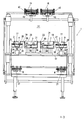
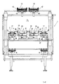
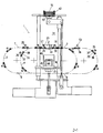
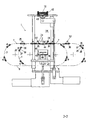
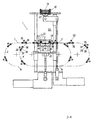
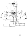
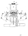
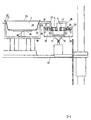
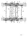
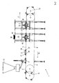
- a conveyor device 1 for container 2 consists essentially of 4 parallel extending link chains 3, 4, 5, 6, each with an upper run 7 and a lower run 8.
- the link chains 3, 4, 5, 6 are deflected in the range of deflection plates 9, 10, so that the respective upper run 7 runs in the conveying direction 11, while the lower run 8 runs in the opposite direction 12.
- the containers 2 are conveyed to various stations, for example in a filling station 13, in which they are filled with a product, such as a food and in a Verdeckelstation 14, in which the filled container 2 is closed, for example with a lid 16 is provided. Similarly, a sealing film 15 is sealed onto the filled container 2 optionally in a sealing station.
- the container 2 is held in holders 17, 18. These may be formed as rods which extend between mutually associated link chains, for example, between the two outboard link chains 3, 6 and between the two in-running chains 4, 5.
- the distance between the two brackets 17, 18 so selected in that between them the containers 2 can hang independently of their external shape, for example in the region of their outer walls 19, 20 or in the region of a collar 21, 22 which respectively surrounds their filling openings 23, 24.
- the brackets 17, 18 are connected via coupling members 25, 26, 27, 28 with the link chains 3, 4, 5, 6.
- the link chains 3, 4, 5, 6 have link pins 29, 30, each of an outer boundary 31, 32 in opposite directions from each of the adjacent link chain sticking out pointing away.
- the coupling member 25, 26, 27, 28 is pivotally mounted.
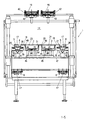
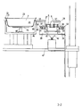
- the coupling member 25, 26, 27, 28 is formed in the shape of an isosceles triangle 35, in the base 36 in each case two rollers 37, 38 are rotatably mounted, which during transport of the link chains 3, 4, 5, 6 on a plane 53rd , which is stored on a foundation 39, unroll.
- This foundation 39 is arranged with the aid of a pneumatic punch 40 against a guide 41 of the link chains 3, 4, 5, 6 adjustable in height.
- the brackets 17, 18 are pivoted.
- the distance between two mutually adjacent brackets 17, 18 are changed by the one pair of chains 3, 6 with respect to the other pair of chains 4, 5 is moved.
- the distance between the brackets 17, 18 is greater, when moving in the same direction chain pairs 3, 6 and 4, 5, the following chain pair 4, 5 is moved slower than the preceding pair of chains 3, 6.
- the distance is smaller, if when moving in the same direction chain pairs 3, 6 and 4, 5, the subsequent chain pair 4, 5 is moved faster than the leading pair of chains 3, 6.
- the distance is also greater when the one pair of chains 3, 6 in one direction and the other pair of chains 4, 5 moves in the other direction.
- a displaceable in the direction of a bottom 44 of the container 2 plate 45 is provided which is displaceably mounted within a support 46 in the vertical direction.
- This plate 45 is raised together with the support 46 by lifting a crossbar 47 in the direction of the hanging in the brackets 17, 18 container 2.
- the plate 45 is movably supported by its own drive 48 within the support 46 in the vertical direction.
- the support 46 is formed as a rigid box, on the upper limit 49 of the container 2 with its collar 21, 22 can be placed.
- the container 2 must be lifted from the brackets 17, 18, so that below the collar 21, 22 enough space for receiving the upper boundary 49 of the support 46 is. For this purpose, two steps are necessary. On the one hand, the container 2 must be slightly raised with respect to the support 17, 18 supporting it and then be pivoted away from the container 2. By pivoting the coupling members 25, 26, 27, 28, the holder 17, 18 from the collar 21, 22 of the container 2 swung.
- the container 2 is slightly lifted by the plate 45 driven under the bottom 44, so that it comes free of the holders 17, 18 and these can be pivoted.
- the plate 45 is raised within the support 46 to the bottom 44 of the container 2, so that the plate 45 can support the bottom 44 and lift a little.
- the bottom 44 of the container 2 is first supported by lifting the plate 45 again. Then, by lifting the foundation 39 and the guide groove is raised and the coupling member 25, 26, 27, 28 pivoted to its original position in which the brackets 17, 18 extend below the collar 21, 22 and carry this. Subsequently, the plate 45 is moved down into the support 46 and the traverse 47 completely lowered and retracted the plate 45 in the support, so that the container 2 only in the brackets 17, 18 depends and together with these to a discharge station, not shown the conveyor device 1 is transported.
- the function of the conveyor device 1 is as follows: by appropriate method of the link chains 3, 6 and 4, 5 relative to each other, the brackets 25, 26, 27, 28 set to a required container size. After this adjustment, the containers 2 are deposited on the holders 17, 18, so that they can be transported and filled with their respective filling opening in the region of the filling station 13.
- the filled container 2 is conveyed into the capping station 14. There, together with the support 46, the plate 45 is raised until the bottom 44 of the container 2 rests on it. Subsequently, the foundation 39 is lowered by means of the pneumatic punch 40, so that the holders 17, 18 are pivoted and no longer support the collar 21, 22 of the container 2. Then the plate 45 becomes opposite the ground 44 lowered.
- the container 2 is rigidly mounted on the support 46, so that it can be loaded with a considerable pressure for placing a pressure cover or for sealing, without undesirable deformations of the container 2 occur.
- the plate 45 is raised again and the holders 17, 18 are pivoted by lifting the foundation 39 in the direction of the container 2.
- the plate 45 can be sunk by its own drive 48 in the support 46, so that it can be driven together with the support 46 of the cross member 47 in its initial position. Supported on the brackets 17, 18 of the filled and sealed container 2 is conveyed to a dispensing position of the conveying position 1, not shown, and this removed.
Landscapes
- Engineering & Computer Science (AREA)
- Mechanical Engineering (AREA)
- Microelectronics & Electronic Packaging (AREA)
- Supplying Of Containers To The Packaging Station (AREA)
- Auxiliary Devices For And Details Of Packaging Control (AREA)
- Prostheses (AREA)
Claims (23)
- Procédé pour adapter un dispositif de transport (1) destiné au transport de récipients (2) à différents formats de récipients, dans lequel sont associées à chaque récipient (2) au moins deux fixations (17, 18) déplaçables l'une vers l'autre dans une position adaptée au récipient (2), dont chacune est guidée par au moins une chaîne à maillons (3, 4, 5, 6), caractérisé en ce que les fixations (17, 18) sont couplées et découplées sur les chaînes à maillons (3, 4, 5, 6) par des éléments de couplage (25, 28 ; 26, 27) supportés de façon basculante, qui basculent autour d'un boulon de maillon (29, 30) dépassant au-delà d'une délimitation extérieure (31, 32) de la chaînes à maillons (3, 4, 5, 6) et la fixation (17, 18) reliée aux éléments de couplage (25, 28 ; 26, 27) bascule ainsi pour s'écarter ou se rapprocher du récipient en question (2).
- Procédé selon la revendication 1, caractérisé en ce que le récipient (2) est soutenu le long de deux parois latérales (19, 20) qui le délimitent par les fixations (17, 18).
- Procédé selon la revendication 1 ou 2, caractérisé en ce que le récipient (2) est soutenu sur les fixations (17, 18) par un collet (21, 22) qui entoure son ouverture de remplissage (23,24).
- Procédé selon l'une des revendications 1 à 3, caractérisé en ce que les fixations (17, 18) sont déplacées l'une vers l'autre pour s'adapter aux dimensions d'un récipient (2) à transporter dans un sens de transport (11) suivi par le récipient (2) dans le dispositif de transport (1).
- Procédé selon l'une des revendications 1 à 4, caractérisé en ce qu'une distance prévue entre deux fixations (17, 18) associées l'une à l'autre est adaptée à la dimension d'un récipient (2) à mettre en place.
- Procédé selon l'une des revendications 1 à 5, caractérisé en ce que chacune des fixations (17, 18) associées l'une à l'autre est guidée par au moins un moyen de transport par lequel les récipients (2) sont transportés à travers le dispositif de transport (1).
- Procédé selon la revendication 6, caractérisé en ce que la distance prévue entre les fixations (17, 18) est modifiée par le déplacement des moyens de transport l'un vers l'autre.
- Procédé selon la revendication 7, caractérisé en ce que les deux fixations (17, 18) associées à un récipient (2) sont transportées l'une sur une certaine distance dans le sens de transport (11) et l'autre de la même distance dans un sens (12) opposé au sens de transport (11) à partir d'un certains point de départ, de telle sorte que celui-ci est conservé pour tous les formats de récipients réglables et que la distance entre les fixations (17, 18) est inchangée pour le transport d'un certain type de récipient.
- Procédé selon l'une des revendications 6 à 8, caractérisé en ce que le récipient (2) est découplé des fixations (17, 18) qui lui sont associées par le basculement des fixations (17, 18).
- Procédé selon la revendication 9, caractérisé en ce que le récipient (2) est posé sur un support avant d'être découplé des fixations (17, 18).
- Procédé selon la revendication 10, caractérisé en ce que le récipient (2) est soutenu avant que la fixation (17, 18) s'en écarte.
- Procédé selon la revendication 11, caractérisé en ce que le récipient (2) est soutenu par une plaque (45) mobile en direction de son fond (44), sur laquelle le fond (44) est supporté.
- Procédé selon l'une des revendications 10 à 12, caractérisé en ce que le récipient (2) est soutenu après que la fixation (17, 18) s'en est écartée dans un appui (46) rigide en flexion qui l'entoure et dont la délimitation supérieure (49) est levée jusqu'au collet (21, 22) entourant l'ouverture de remplissage (23, 24) du récipient (2).
- Procédé selon la revendication 12 ou 13, caractérisé en ce que la plaque (45) est déplacée à l'intérieur de l'appui (46) en direction du fond (44) du récipient (2).
- Procédé selon l'une des revendications 9 à 14, caractérisé en ce que le récipient (2) est soulevé par la plaque (45) avant que les fixations (17, 18) s'en écartent.
- Procédé selon la revendication 15, caractérisé en ce que les fixations (17, 18) guidées dans les éléments de couplage (25, 26, 27, 28) sont abaissées par le basculement des éléments de couplage (25, 26, 27, 28).
- Procédé selon la revendication 16, caractérisé en ce que les éléments de couplage (25, 26, 27, 28) sont basculés lors du passage d'une tige de guidage (50) qui les contrôle dans un plan de guidage abaissé.
- Dispositif pour adapter un dispositif de transport (1) destiné au transport de récipients (2) à différents formats de récipients, avec au moins deux fixations (17, 18) mobiles indépendamment l'une de l'autre, qui peuvent être positionnées l'une par rapport à l'autre en fonction d'un récipient (2) à transporter par au moins une chaîne à maillons (3, 4, 5, 6) reliée à une fixation (17, 18) à la fois, caractérisé en ce que chaque fixation (17, 18) possède un élément de couplage (25, 28 ; 26, 27) supporté de manière basculante auquel est reliée une chaîne à maillons (3, 6 ; 4, 5), dont la délimitation extérieure (31, 32) porte en saillie un boulon de maillon (29, 30) sur lequel l'élément de couplage (25, 26, 27, 28) est supporté de façon à pouvoir basculer d'une position couplant la fixation (17, 18) au récipient (2) à une position de découplage et revenir de celle-ci à la position de couplage.
- Dispositif selon la revendication 18, caractérisé en ce que les fixations (17, 18) sont approximativement parallèles l'une à l'autre le long de deux parois extérieures (19, 20) délimitant le récipient (2).
- Dispositif selon la revendication 18 ou 19, caractérisé en ce que les fixations (17, 18) passent en dessous d'un collet (21, 22) qui borde les parois extérieures (19, 20) du récipient au niveau de son ouverture de remplissage (23, 24).
- Dispositif selon l'une des revendications 18 à 20, caractérisé en ce qu'il est prévu entre les fixations (17, 18) associées l'une à l'autre une distance modifiable en fonction des dimensions de chaque récipient (2) à transporter.
- Dispositif selon la revendication 21, caractérisé en ce que le récipient (2) peut être découplé des fixations (17, 18) dans une position soulevée par celles-ci.
- Dispositif selon la revendication 18 à 22, caractérisé en ce que l'élément de couplage (25, 26, 27, 28) est supporté avec possibilité de basculement sur un boulon de maillon (29, 30) qui dépasse d'un côté d'une délimitation extérieure (31, 32) de la chaîne à maillons 3,4,5,6 et est guidé sur deux galets (33) supportés avec possibilité de rotation des deux côtés du boulon de maillon (29, 30), qui sont guidés au niveau d'une position découplant la fixation (17, 18) du récipient (2), en passant dans un plan (53) qui présente une descente faisant basculer l'élément de couplage (25, 26, 27, 28), dans laquelle les fixations (17, 18) sont écartées du récipient (2) par basculement.
Applications Claiming Priority (2)
| Application Number | Priority Date | Filing Date | Title |
|---|---|---|---|
| DE10340270 | 2003-08-29 | ||
| DE10340270A DE10340270A1 (de) | 2003-08-29 | 2003-08-29 | Fördervorrichtung und Verfahren zum Anpassen |
Publications (2)
| Publication Number | Publication Date |
|---|---|
| EP1520809A1 EP1520809A1 (fr) | 2005-04-06 |
| EP1520809B1 true EP1520809B1 (fr) | 2009-08-12 |
Family
ID=34305577
Family Applications (1)
| Application Number | Title | Priority Date | Filing Date |
|---|---|---|---|
| EP04020542A Expired - Lifetime EP1520809B1 (fr) | 2003-08-29 | 2004-08-30 | Convoyeur et méthode d'ajustement à des conteneurs de tailles différentes |
Country Status (3)
| Country | Link |
|---|---|
| EP (1) | EP1520809B1 (fr) |
| AT (1) | ATE439319T1 (fr) |
| DE (2) | DE10340270A1 (fr) |
Cited By (1)
| Publication number | Priority date | Publication date | Assignee | Title |
|---|---|---|---|---|
| DE102017109406A1 (de) * | 2017-05-03 | 2018-11-08 | Tpv Gmbh | Transportvorrichtung zum Transportieren von Behältern sowie Verfahren zu dessen Betrieb |
Families Citing this family (10)
| Publication number | Priority date | Publication date | Assignee | Title |
|---|---|---|---|---|
| EP1743840A1 (fr) * | 2005-07-11 | 2007-01-17 | Aseptis, S.L. | Convoyeur d'ajustement à des conteneurs de tailles différentes |
| DE102005034806A1 (de) * | 2005-07-21 | 2007-01-25 | Herbert Grunwald Gmbh | Abfüll- und/oder Verpackungsmaschine mit einer Transporteinrichtung |
| DE102006004926A1 (de) * | 2006-02-01 | 2007-08-02 | CFS Bühl GmbH | Mit dem Rand einer Verpackungsmulde zusammenwirkende Transportbänder |
| FR2922193A1 (fr) * | 2007-10-10 | 2009-04-17 | Mecaplastic Soc Par Actions Si | Unite d'operculage a plateaux pour recipients de dimensions variables et son utilisation |
| DE102012006699A1 (de) * | 2012-03-30 | 2013-10-02 | Multivac Sepp Haggenmüller Gmbh & Co. Kg | Mehrreihige Siegelstation |
| CN108657727B (zh) * | 2018-05-22 | 2024-06-11 | 无锡职业技术学院 | 一种柔性卧式钢桶输送装置 |
| CN110422358B (zh) * | 2019-08-14 | 2024-07-30 | 昆山八一九包装机械有限公司 | 应用于盒装食品的灌注封装装置 |
| DE102021104302A1 (de) * | 2021-02-23 | 2022-08-25 | Syntegon Technology Gmbh | Vorrichtung und Verfahren zum kraftgesteuerten Verschließen von pharmazeutischen Behältnissen |
| CN114516449A (zh) * | 2022-02-28 | 2022-05-20 | 浙江希望机械有限公司 | 一种同步变距输送装置及应用该装置的泡罩装盒一体机 |
| CN114524133A (zh) * | 2022-02-28 | 2022-05-24 | 浙江希望机械有限公司 | 一种高速泡罩装盒一体机 |
Family Cites Families (4)
| Publication number | Priority date | Publication date | Assignee | Title |
|---|---|---|---|---|
| US3857474A (en) * | 1973-09-25 | 1974-12-31 | Hercules Inc | Adjustable container conveyor for filling machine |
| FR2613703B1 (fr) * | 1987-04-07 | 1992-05-22 | Diffusion Ind | Convoyeur a plaques permettant notamment le transport de recipients |
| JP2541918Y2 (ja) * | 1991-05-07 | 1997-07-23 | 四国化工機株式会社 | 容器搬送コンベヤ |
| DE19740988A1 (de) * | 1997-09-18 | 1999-03-25 | Lieder Maschinenbau Gmbh & Co | Vorrichtung und Verfahren zum Versiegeln von Verpackungsbehältern |
-
2003
- 2003-08-29 DE DE10340270A patent/DE10340270A1/de not_active Ceased
-
2004
- 2004-08-30 EP EP04020542A patent/EP1520809B1/fr not_active Expired - Lifetime
- 2004-08-30 AT AT04020542T patent/ATE439319T1/de not_active IP Right Cessation
- 2004-08-30 DE DE502004009878T patent/DE502004009878D1/de not_active Expired - Lifetime
Cited By (1)
| Publication number | Priority date | Publication date | Assignee | Title |
|---|---|---|---|---|
| DE102017109406A1 (de) * | 2017-05-03 | 2018-11-08 | Tpv Gmbh | Transportvorrichtung zum Transportieren von Behältern sowie Verfahren zu dessen Betrieb |
Also Published As
| Publication number | Publication date |
|---|---|
| DE10340270A1 (de) | 2005-06-23 |
| DE502004009878D1 (de) | 2009-09-24 |
| ATE439319T1 (de) | 2009-08-15 |
| EP1520809A1 (fr) | 2005-04-06 |
Similar Documents
| Publication | Publication Date | Title |
|---|---|---|
| DE69008458T2 (de) | Verfahren und Apparat für die Puffersteuerung in Fördersystemen. | |
| DE3223848C3 (de) | Vorrichtung zum ansetzen von abstandhalterrahmen | |
| EP1598273B1 (fr) | Machine d'emballage et procédé pour fermer des récipients | |
| EP2439142B1 (fr) | Dispositif de transport et d'introduction de produits d'emballage | |
| DE69702266T2 (de) | Vorrichtung zum ausgeben von paletten | |
| EP3666696B1 (fr) | Dispositif et procede pour manipuler des couches de marchandises unitaires superposees | |
| DE3219267A1 (de) | Automatische verpackungsvorrichtung | |
| EP0421148A2 (fr) | Dispositif et procédé pour transporter et empiler des pièces découpées pour la production des paquets de cigarettes | |
| EP2883684B1 (fr) | Procédé et machine d'emballage dotée d'un porte-objet mobile | |
| DE102020134792A1 (de) | Schließvorrichtung zum Verschließen pharmazeutischer Behälter und System zum Verarbeiten pharmazeutischer Behälter | |
| DE2714352B2 (de) | Vorrichtung zum selbsttätigen Ausziehen von Stapeln von fertigen, aus einer Kunststoffolie warmgeformten Hohlgegenständen aus einer Stapelstation | |
| EP2275351B1 (fr) | Machine de fermeture de barquettes | |
| EP1520809A1 (fr) | Convoyeur et méthode d'ajustement à des conteneurs de tailles différentes | |
| DE3424233A1 (de) | Verfahren und vorrichtung zum befuellen von kartons | |
| EP0290747B1 (fr) | Station de remplissage pour une machine de remplissage et de fermeture de cartouches | |
| DE3114190A1 (de) | Vorrichtung zum automatischen fuellen und verschliessen von kartonbehaeltern | |
| DE19509057C2 (de) | Vorrichtung zum Überführen und Stapeln von aus einer thermoplastischen Kunststoffolie tiefgezogenen und ausgestanzten Behältern | |
| DE68911850T2 (de) | Versiegelungsvorrichtung für Behälter. | |
| DE3141075A1 (de) | Zufuehreinrichtung fuer blechstreifenstapel zur zufuhr zu einem stanzautomaten | |
| DE2636320A1 (de) | Verfahren und maschine zum automatischen palettisieren von gegenstaenden | |
| EP1314536B1 (fr) | Dispositif pour le formage de récipients en matière plastique à partir d'une bande, et de stockage de ces récipients dans un receptacle | |
| DE19740988A1 (de) | Vorrichtung und Verfahren zum Versiegeln von Verpackungsbehältern | |
| DE2508357A1 (de) | Vorrichtung zum ueberfuehren empfindlicher gegenstaende von einem foerderer mit kontinuierlicher bewegung auf einen foerderer mit intermittierender bewegung | |
| DE2731900A1 (de) | Vorrichtung und verfahren zum verpacken von einheiten in behaeltern | |
| EP3449079B1 (fr) | Procédé et dispositif de scellement d'ébauches de vitrage isolant |
Legal Events
| Date | Code | Title | Description |
|---|---|---|---|
| PUAI | Public reference made under article 153(3) epc to a published international application that has entered the european phase |
Free format text: ORIGINAL CODE: 0009012 |
|
| AK | Designated contracting states |
Kind code of ref document: A1 Designated state(s): AT BE BG CH CY CZ DE DK EE ES FI FR GB GR HU IE IT LI LU MC NL PL PT RO SE SI SK TR |
|
| AX | Request for extension of the european patent |
Extension state: AL HR LT LV MK |
|
| 17P | Request for examination filed |
Effective date: 20051005 |
|
| AKX | Designation fees paid |
Designated state(s): AT BE BG CH CY CZ DE DK EE ES FI FR GB GR HU IE IT LI LU MC NL PL PT RO SE SI SK TR |
|
| RAP1 | Party data changed (applicant data changed or rights of an application transferred) |
Owner name: ROBOT FOOD TECH LIMITED |
|
| 17Q | First examination report despatched |
Effective date: 20051104 |
|
| 17Q | First examination report despatched |
Effective date: 20051104 |
|
| RAP1 | Party data changed (applicant data changed or rights of an application transferred) |
Owner name: ROBOT FOOD TECHNOLOGIES GERMANY GMBH |
|
| GRAP | Despatch of communication of intention to grant a patent |
Free format text: ORIGINAL CODE: EPIDOSNIGR1 |
|
| GRAS | Grant fee paid |
Free format text: ORIGINAL CODE: EPIDOSNIGR3 |
|
| GRAA | (expected) grant |
Free format text: ORIGINAL CODE: 0009210 |
|
| AK | Designated contracting states |
Kind code of ref document: B1 Designated state(s): AT BE BG CH CY CZ DE DK EE ES FI FR GB GR HU IE IT LI LU MC NL PL PT RO SE SI SK TR |
|
| REG | Reference to a national code |
Ref country code: GB Ref legal event code: FG4D Free format text: NOT ENGLISH |
|
| REG | Reference to a national code |
Ref country code: CH Ref legal event code: EP |
|
| REG | Reference to a national code |
Ref country code: IE Ref legal event code: FG4D |
|
| REF | Corresponds to: |
Ref document number: 502004009878 Country of ref document: DE Date of ref document: 20090924 Kind code of ref document: P |
|
| PG25 | Lapsed in a contracting state [announced via postgrant information from national office to epo] |
Ref country code: ES Free format text: LAPSE BECAUSE OF FAILURE TO SUBMIT A TRANSLATION OF THE DESCRIPTION OR TO PAY THE FEE WITHIN THE PRESCRIBED TIME-LIMIT Effective date: 20091123 Ref country code: FI Free format text: LAPSE BECAUSE OF FAILURE TO SUBMIT A TRANSLATION OF THE DESCRIPTION OR TO PAY THE FEE WITHIN THE PRESCRIBED TIME-LIMIT Effective date: 20090812 Ref country code: SE Free format text: LAPSE BECAUSE OF FAILURE TO SUBMIT A TRANSLATION OF THE DESCRIPTION OR TO PAY THE FEE WITHIN THE PRESCRIBED TIME-LIMIT Effective date: 20090812 |
|
| PGFP | Annual fee paid to national office [announced via postgrant information from national office to epo] |
Ref country code: IE Payment date: 20091028 Year of fee payment: 6 |
|
| NLV1 | Nl: lapsed or annulled due to failure to fulfill the requirements of art. 29p and 29m of the patents act | ||
| PG25 | Lapsed in a contracting state [announced via postgrant information from national office to epo] |
Ref country code: PL Free format text: LAPSE BECAUSE OF FAILURE TO SUBMIT A TRANSLATION OF THE DESCRIPTION OR TO PAY THE FEE WITHIN THE PRESCRIBED TIME-LIMIT Effective date: 20090812 Ref country code: SI Free format text: LAPSE BECAUSE OF FAILURE TO SUBMIT A TRANSLATION OF THE DESCRIPTION OR TO PAY THE FEE WITHIN THE PRESCRIBED TIME-LIMIT Effective date: 20090812 Ref country code: NL Free format text: LAPSE BECAUSE OF FAILURE TO SUBMIT A TRANSLATION OF THE DESCRIPTION OR TO PAY THE FEE WITHIN THE PRESCRIBED TIME-LIMIT Effective date: 20090812 |
|
| BERE | Be: lapsed |
Owner name: ROBOT FOOD TECHNOLOGIES GERMANY G.M.B.H. Effective date: 20090831 |
|
| REG | Reference to a national code |
Ref country code: IE Ref legal event code: FD4D |
|
| PG25 | Lapsed in a contracting state [announced via postgrant information from national office to epo] |
Ref country code: PT Free format text: LAPSE BECAUSE OF FAILURE TO SUBMIT A TRANSLATION OF THE DESCRIPTION OR TO PAY THE FEE WITHIN THE PRESCRIBED TIME-LIMIT Effective date: 20091212 Ref country code: MC Free format text: LAPSE BECAUSE OF NON-PAYMENT OF DUE FEES Effective date: 20090831 Ref country code: BG Free format text: LAPSE BECAUSE OF FAILURE TO SUBMIT A TRANSLATION OF THE DESCRIPTION OR TO PAY THE FEE WITHIN THE PRESCRIBED TIME-LIMIT Effective date: 20091112 |
|
| REG | Reference to a national code |
Ref country code: CH Ref legal event code: PL |
|
| PG25 | Lapsed in a contracting state [announced via postgrant information from national office to epo] |
Ref country code: CH Free format text: LAPSE BECAUSE OF NON-PAYMENT OF DUE FEES Effective date: 20090831 Ref country code: LI Free format text: LAPSE BECAUSE OF NON-PAYMENT OF DUE FEES Effective date: 20090831 Ref country code: DK Free format text: LAPSE BECAUSE OF FAILURE TO SUBMIT A TRANSLATION OF THE DESCRIPTION OR TO PAY THE FEE WITHIN THE PRESCRIBED TIME-LIMIT Effective date: 20090812 Ref country code: EE Free format text: LAPSE BECAUSE OF FAILURE TO SUBMIT A TRANSLATION OF THE DESCRIPTION OR TO PAY THE FEE WITHIN THE PRESCRIBED TIME-LIMIT Effective date: 20090812 Ref country code: CZ Free format text: LAPSE BECAUSE OF FAILURE TO SUBMIT A TRANSLATION OF THE DESCRIPTION OR TO PAY THE FEE WITHIN THE PRESCRIBED TIME-LIMIT Effective date: 20090812 Ref country code: IE Free format text: LAPSE BECAUSE OF FAILURE TO SUBMIT A TRANSLATION OF THE DESCRIPTION OR TO PAY THE FEE WITHIN THE PRESCRIBED TIME-LIMIT Effective date: 20090812 Ref country code: RO Free format text: LAPSE BECAUSE OF FAILURE TO SUBMIT A TRANSLATION OF THE DESCRIPTION OR TO PAY THE FEE WITHIN THE PRESCRIBED TIME-LIMIT Effective date: 20090812 |
|
| PG25 | Lapsed in a contracting state [announced via postgrant information from national office to epo] |
Ref country code: SK Free format text: LAPSE BECAUSE OF FAILURE TO SUBMIT A TRANSLATION OF THE DESCRIPTION OR TO PAY THE FEE WITHIN THE PRESCRIBED TIME-LIMIT Effective date: 20090812 |
|
| PLBE | No opposition filed within time limit |
Free format text: ORIGINAL CODE: 0009261 |
|
| STAA | Information on the status of an ep patent application or granted ep patent |
Free format text: STATUS: NO OPPOSITION FILED WITHIN TIME LIMIT |
|
| PG25 | Lapsed in a contracting state [announced via postgrant information from national office to epo] |
Ref country code: BE Free format text: LAPSE BECAUSE OF NON-PAYMENT OF DUE FEES Effective date: 20090831 |
|
| 26N | No opposition filed |
Effective date: 20100517 |
|
| GBPC | Gb: european patent ceased through non-payment of renewal fee |
Effective date: 20091112 |
|
| PG25 | Lapsed in a contracting state [announced via postgrant information from national office to epo] |
Ref country code: GR Free format text: LAPSE BECAUSE OF FAILURE TO SUBMIT A TRANSLATION OF THE DESCRIPTION OR TO PAY THE FEE WITHIN THE PRESCRIBED TIME-LIMIT Effective date: 20091113 |
|
| PG25 | Lapsed in a contracting state [announced via postgrant information from national office to epo] |
Ref country code: AT Free format text: LAPSE BECAUSE OF NON-PAYMENT OF DUE FEES Effective date: 20090830 |
|
| PG25 | Lapsed in a contracting state [announced via postgrant information from national office to epo] |
Ref country code: GB Free format text: LAPSE BECAUSE OF NON-PAYMENT OF DUE FEES Effective date: 20091112 |
|
| PG25 | Lapsed in a contracting state [announced via postgrant information from national office to epo] |
Ref country code: IT Free format text: LAPSE BECAUSE OF FAILURE TO SUBMIT A TRANSLATION OF THE DESCRIPTION OR TO PAY THE FEE WITHIN THE PRESCRIBED TIME-LIMIT Effective date: 20090812 |
|
| PG25 | Lapsed in a contracting state [announced via postgrant information from national office to epo] |
Ref country code: LU Free format text: LAPSE BECAUSE OF NON-PAYMENT OF DUE FEES Effective date: 20090830 |
|
| REG | Reference to a national code |
Ref country code: FR Ref legal event code: ST Effective date: 20110502 |
|
| PG25 | Lapsed in a contracting state [announced via postgrant information from national office to epo] |
Ref country code: HU Free format text: LAPSE BECAUSE OF FAILURE TO SUBMIT A TRANSLATION OF THE DESCRIPTION OR TO PAY THE FEE WITHIN THE PRESCRIBED TIME-LIMIT Effective date: 20100213 |
|
| REG | Reference to a national code |
Ref country code: GB Ref legal event code: S28 Free format text: APPLICATION FILED |
|
| PG25 | Lapsed in a contracting state [announced via postgrant information from national office to epo] |
Ref country code: FR Free format text: LAPSE BECAUSE OF NON-PAYMENT OF DUE FEES Effective date: 20091012 |
|
| PG25 | Lapsed in a contracting state [announced via postgrant information from national office to epo] |
Ref country code: TR Free format text: LAPSE BECAUSE OF FAILURE TO SUBMIT A TRANSLATION OF THE DESCRIPTION OR TO PAY THE FEE WITHIN THE PRESCRIBED TIME-LIMIT Effective date: 20090812 |
|
| PG25 | Lapsed in a contracting state [announced via postgrant information from national office to epo] |
Ref country code: CY Free format text: LAPSE BECAUSE OF FAILURE TO SUBMIT A TRANSLATION OF THE DESCRIPTION OR TO PAY THE FEE WITHIN THE PRESCRIBED TIME-LIMIT Effective date: 20090812 |
|
| REG | Reference to a national code |
Ref country code: GB Ref legal event code: S28 Free format text: RESTORATION ALLOWED Effective date: 20120123 |
|
| PGFP | Annual fee paid to national office [announced via postgrant information from national office to epo] |
Ref country code: GB Payment date: 20161027 Year of fee payment: 13 |
|
| PGFP | Annual fee paid to national office [announced via postgrant information from national office to epo] |
Ref country code: DE Payment date: 20170831 Year of fee payment: 14 |
|
| GBPC | Gb: european patent ceased through non-payment of renewal fee |
Effective date: 20170830 |
|
| PG25 | Lapsed in a contracting state [announced via postgrant information from national office to epo] |
Ref country code: GB Free format text: LAPSE BECAUSE OF NON-PAYMENT OF DUE FEES Effective date: 20170830 |
|
| REG | Reference to a national code |
Ref country code: DE Ref legal event code: R119 Ref document number: 502004009878 Country of ref document: DE |
|
| PG25 | Lapsed in a contracting state [announced via postgrant information from national office to epo] |
Ref country code: DE Free format text: LAPSE BECAUSE OF NON-PAYMENT OF DUE FEES Effective date: 20190301 |