EP1520823A1 - Ventilsystem für die Zählrolle einer Ineinanderfaltmaschine - Google Patents
Ventilsystem für die Zählrolle einer Ineinanderfaltmaschine Download PDFInfo
- Publication number
- EP1520823A1 EP1520823A1 EP04256133A EP04256133A EP1520823A1 EP 1520823 A1 EP1520823 A1 EP 1520823A1 EP 04256133 A EP04256133 A EP 04256133A EP 04256133 A EP04256133 A EP 04256133A EP 1520823 A1 EP1520823 A1 EP 1520823A1
- Authority
- EP
- European Patent Office
- Prior art keywords
- vacuum
- spool
- roll
- count
- chambers
- Prior art date
- Legal status (The legal status is an assumption and is not a legal conclusion. Google has not performed a legal analysis and makes no representation as to the accuracy of the status listed.)
- Granted
Links
Images


Classifications
-
- B—PERFORMING OPERATIONS; TRANSPORTING
- B65—CONVEYING; PACKING; STORING; HANDLING THIN OR FILAMENTARY MATERIAL
- B65H—HANDLING THIN OR FILAMENTARY MATERIAL, e.g. SHEETS, WEBS, CABLES
- B65H29/00—Delivering or advancing articles from machines; Advancing articles to or into piles
- B65H29/66—Advancing articles in overlapping streams
-
- B—PERFORMING OPERATIONS; TRANSPORTING
- B65—CONVEYING; PACKING; STORING; HANDLING THIN OR FILAMENTARY MATERIAL
- B65H—HANDLING THIN OR FILAMENTARY MATERIAL, e.g. SHEETS, WEBS, CABLES
- B65H33/00—Forming counted batches in delivery pile or stream of articles
- B65H33/12—Forming counted batches in delivery pile or stream of articles by creating gaps in the stream
-
- B—PERFORMING OPERATIONS; TRANSPORTING
- B65—CONVEYING; PACKING; STORING; HANDLING THIN OR FILAMENTARY MATERIAL
- B65H—HANDLING THIN OR FILAMENTARY MATERIAL, e.g. SHEETS, WEBS, CABLES
- B65H45/00—Folding thin material
- B65H45/12—Folding articles or webs with application of pressure to define or form crease lines
- B65H45/16—Rotary folders
- B65H45/162—Rotary folders with folding jaw cylinders
-
- B—PERFORMING OPERATIONS; TRANSPORTING
- B65—CONVEYING; PACKING; STORING; HANDLING THIN OR FILAMENTARY MATERIAL
- B65H—HANDLING THIN OR FILAMENTARY MATERIAL, e.g. SHEETS, WEBS, CABLES
- B65H45/00—Folding thin material
- B65H45/12—Folding articles or webs with application of pressure to define or form crease lines
- B65H45/24—Interfolding sheets, e.g. cigarette or toilet papers
-
- B—PERFORMING OPERATIONS; TRANSPORTING
- B65—CONVEYING; PACKING; STORING; HANDLING THIN OR FILAMENTARY MATERIAL
- B65H—HANDLING THIN OR FILAMENTARY MATERIAL, e.g. SHEETS, WEBS, CABLES
- B65H2406/00—Means using fluid
- B65H2406/30—Suction means
- B65H2406/33—Rotary suction means, e.g. roller, cylinder or drum
-
- B—PERFORMING OPERATIONS; TRANSPORTING
- B65—CONVEYING; PACKING; STORING; HANDLING THIN OR FILAMENTARY MATERIAL
- B65H—HANDLING THIN OR FILAMENTARY MATERIAL, e.g. SHEETS, WEBS, CABLES
- B65H2701/00—Handled material; Storage means
- B65H2701/10—Handled articles or webs
- B65H2701/19—Specific article or web
- B65H2701/1924—Napkins or tissues, e.g. dressings, toweling, serviettes, kitchen paper and compresses
Definitions
- This invention generally relates to an interfolding machine for folding sheets of material, and more specifically, to an interfolding machine that includes a count roll to form a separation in a stack of interfolded sheets at a predetermined sheet.
- Interfolding of a web or sheet material is frequently performed using folding rolls of a folding machine.
- the folding rolls are operable to fold a series of successive sheets that are cut from one or more webs and supplied to the folding rolls in an overlapping relationship.
- the sheets are cut against a bed roll by a knife roll, and the sheets are then supplied to a retard roll that functions to provide the desired overlapping relationship of the sheets.
- the retard roll the sheets are advanced by a lap roll and are then supplied to the folding rolls for interfolding, to create a stack of interfolded sheets at the discharge of the folding rolls.
- a count roll is located adjacent the lap roll, and rotates in a timed relationship with the lap roll.
- the count roll is selectively operable to eliminate the sheet overlap at a desired sheet count, in order to create a separation in the supply of overlapped sheets to the folding rolls.
- the separation in the supply of sheets to the folding rolls functions to separate the stack of sheets discharged from the folding rolls into adjacent stacks or logs of sheets, each of which has a desired sheet count.
- the sheet overlap is interrupted by means of a vacuum system in the count roll that folds the leading edge of one of the sheets onto itself at the desired count.
- the vacuum system is selectively actuated to engage the leading edge of the sheet as the sheets is transported on the lap roll, and carries and/or retains the leading edge of the sheet while the remainder of the sheet is advanced by the lap roll.
- the count roll then releases the leading edge of the sheet, and the retention of the remainder of the sheet on the count roll creates the sheet fold that eliminates the overlap between the leading edge of the sheet and the trailing edge of the downstream sheet.
- known count roll systems for interfolding machines have drawbacks and limitations.
- the operational speed of the interfolding machine is limited by a relatively short switching time that is available for actuating the vacuum system to turn the count roll valves on and off.
- known count rolls use two vacuum ports on the count roll that are 180° apart, which can only provide an even count of sheets.
- a count assembly that provides the ability to form a separation of successive sheets of material through an interfolding machine at a desired sheet count.
- the count assembly includes a count roll that is selectively supplied with vacuum from a vacuum assembly, which includes a manifold having a plurality of manifold ports coupled to a valve body having a plurality of interior chambers.
- a spool is located within a cavity defined by the valve body.
- the spool includes a plurality of spool ports to provide a plurality of respective vacuum paths to a rotating count roll.
- the spool also includes a plurality of machined openings along a perimeter or outer surface, and each machined opening in the spool communicates a respective manifold port with a respective interior chamber disposed in the valve body.
- the invention also provides an interfolding machine for interfolding sheets of material, which are separated at a predetermined count of sheets.
- the interfolding machine includes a roll configured to count successive sheets of the material through the interfolding machine.
- the roll generally includes a series of holes or ports configured to communicate vacuum to the surface of the roll at a predetermined sheet count and at a desired point in rotation of the roll.
- the interfolding machine further includes a vacuum assembly that selectively communicates vacuum pressure to the holes or ports of the roll.
- the vacuum assembly includes a manifold having a series of manifold ports, and a valve body having a series of chambers, each of which is in communication with one of the series of manifold ports.
- the vacuum assembly further includes a spool inserted in the valve body.
- the spool is connected to the roll so as to rotate with the roll, and includes a plurality of spool ports along a circumference thereof to provide respective paths to communicate the vacuum pressure to the holes or ports of the folding roll.
- Each opening in the spool communicates one of the manifold openings with one of the chambers of the valve body.
- the vacuum assembly further includes a control valve for selectively exposing at least one of the valve chambers to atmosphere such that the roll selectively releases the web material at a predetermined point in rotation of the roll.
- the invention also provides a method of separating successive sheets of overlapped sheets of material at a desired sheet count.
- the method generally includes the acts of providing a control valve, a spool, and a count roll, the count roll configured to create a fold separating the successive sheets of web material at a desired sheet count.
- the spool includes a plurality of chambers, each of which is configured to communicate a vacuum pressure at a plurality of ports along a perimeter of the spool with a plurality of holes in an outer surface of the count roll.
- the method further includes the acts of rotating the spool with respect to the control valve; aligning one or more of the chambers in the spool with an opening in the control valve; communicating one or more of the aligned chambers with atmosphere via the opening in the control valve; and releasing the vacuum pressure in one or more of the aligned chambers to atmosphere.
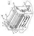
- an interfolding machine 25 is operable to convert a web of material 30 into a stack of interfolded sheets of material shown at 32.
- Interfolding machine 25 incorporates a count roll valve system in accordance with the present invention, and generally includes a first pull roll 35 and a second pull roll 40 that receive the web of material 30 along a path (illustrated by an arrow 42 in FIG. 2) from a supply roll (not shown) into the interfolding machine 20.
- the first and second pull rolls 35 and 40 define a nip through which the web of material 30 passes, and function to unwind the web of material 30 and feed the web of material 30 in a path (illustrated by an arrow 44 in FIG.
- the knife roll 50 cuts the web of material 30 into sheets, each of which has a predetermined length, and the bed roll 45 carries the sheets of material along a path (illustrated by arrow 52 in FIG. 2) toward and through a nip defined between bed roll 45 and a retard roll 55, which rotates at a slower speed of rotation than the bed roll 45.
- the retard roll 55 cooperates with a nip roller assembly 60 (FIG. 2) to form an overlap between the consecutive sheets of material.
- the retard roll 55 carries the overlapped sheets of material along a path (illustrated by arrow 68 in FIG. 2) to a lap roll 65.
- the lap roll 65 works in combination with the count roll 20 to eliminate the overlap between adjacent sheets of material at a predetermined sheet count, so as to create a separation in the stack 32 of interfolded sheets discharged from the interfolding machine 25.
- the lap roll 65 carries the overlapped sheets 30 along a path (illustrated by arrow 78 in FIG. 2) toward a nip defined between a first assist roll 80 and an adjacent second assist roll 85.
- the first and second assist rolls 80 and 85 feed the sheets of the material to a nip defined between a first folding roll 90 and a second folding roll 95.
- the first and second folding rolls 90 and 95 generally rotate in opposite directions (illustrated by arrows 96 and 98, respectively, in FIG. 2) to receive the overlapped sheets of material 30 therebetween.
- the periphery of the first folding roll 90 generally includes a series of the tucker assemblies 105 and gripper assemblies 100 uniformly and alternately spaced to interact with a series of tucker assemblies 105 and gripper assemblies 100 of the adjacent second folding roll 95.
- the series of alternately spaced tucker assemblies 105 and gripper assemblies 100 of the first and second folding rolls 90 and 95 interact to grip, carry, and release the sheets of material in a desired manner so as to form stack 32 of interfolded sheets.
- the folding rolls 90 and 95 may be driven by a drive system 110 having a drive belt assembly 115 (FIG. 1).
- the stack 32 of interfolded sheets is discharged from between the first and second folding rolls 90 and 95 in a generally vertically-aligned fashion.
- the stack 32 of interfolded sheets may be supplied to a discharge and transfer system (not shown), which guides and conveys the stack 32 from the generally vertically-aligned orientation at the discharge of the interfolding machine 25 to a generally horizontally-aligned movement.
- a discharge and transfer system is described in U.S. Patent No. 6,712,746 entitled “Discharge and Transfer System for Interfolded Sheets," filed May 5, 2000, the disclosure of which is hereby incorporated herein by reference in its entirety.
- Another representative discharge and transfer system is illustrated in copending application serial no. ______ filed ______ (atty docket no. 368.005), the disclosure of which is also hereby incorporated herein by reference in its entirety.
- FIGS. 3-7 show a count roll valve assembly 130 of the present invention, which is mounted to each end of count roll 20.
- Count roll 20 is rotatably mounted to the frame of interfolding machine 25 by a pair of bearing box assemblies 132.
- Each count roll valve assembly 130 generally includes a pair of ball bearings 135, a rotating spool 140, a valve body 145, a pair of wear plates 150, an OFF valve 155, and a manifold cover 160.
- Each roll journal 170 includes a flange 176 that is directly connected one of the ends of count roll 20, in a manner as is known.
- Flange 176 defines port paths 185 that are aligned and communicate with port paths 185 that open onto the ends of count roll 20.
- Port paths 185 of flange 176 communicate with separate interior chambers or passages 200a-d formed in the body of spool 140.
- the rotating spool 140 also includes radially and axially spaced machined openings or ports 210a-d that open onto the outer surface 212 of the body of spool 140.
- Each opening 210a-d communicates with one of the separate interior chamber 200a - d disposed in the spool 140, establishing communication with the outer surface of spool 140.
- Each chamber 200a- 200d connects one of the distinct openings 210a-d to one of the respective port paths 185a-d and to the respective holes 218a-d along the outer surface of the count roll 20.
- valve body 145 does not rotate, and is supported on spool 140 by bearings 135, which are affixed to the ends of spool 140 and within inwardly facing recesses formed in the ends of valve body 145. Wear plates 150 straddle the outer one of bearings 135 at the bearing box 132/ frame side 222 (See FIG. 1) of the assembly 20.
- Valve body 145 is a generally cylindrical member, and includes a series of circumferential recesses 148a, 148b, 148c and 148d that extend inwardly from its outer surface.
- Valve body 145 defines an interior 149 within which spool 140 is received, and recesses 148a-148d communicate with valve body interior 149 through respective passages 151a-151d (FIGS. 4,5).
- Manifold 160 generally includes a series of four C-shaped cover components 160a-d interconnected with a series of four C-shaped vacuum inlet components 165a-d.
- the width of each of the cover components 160a-d and respective vacuum inlet components 165a-d can vary.
- the preferred cover components 160a-d each extends a first portion of the circumference of the manifold 160, and each of the vacuum inlet components 165a-d extends the remaining circumference of the manifold 160.
- the manifold 160 further includes a series of gaskets 230 disposed between adjacent cover components 160a-d and vacuum inlet components 165a-d.
- Respective cover components 160a-160d and respective vacuum inlet components 165a-165d are secured together to enclose respective valve body recesses 148a-148d.
- manifold 160 defines a series of annular vacuum supply cavities, each of which is supplied with vacuum from a vacuum source connected to vacuum inlet components 165a-165d, and which communicate with valve body interior through passages 151a-151d.
- the specific construction of manifold 160 may vary form that which is shown and described, which is not limiting on the invention.
- the OFF valve 155 is generally a port cover plate structure that overlies the end of the spool 140 opposite plate portion 144. OFF valve 155 is spring-loaded, stationary and presses against the outer wear plate 150.
- OFF valve 155 generally includes a U-shaped opening 225 through which roll journal 170 extends. Opening 225 in OFF valve 155 selectively communicates chambers or passages 200a-d with atmosphere during rotation of count valve 20 and spool 140.
- the energized or activated port passes the U-shaped cutout in valve 155, the respective port is exposed to the atmosphere, which functions to cut off the supply of vacuum pressure to the holes 218a-d of the count roll 20. This release of vacuum pressure functions to release engagement of the sheet 30 with the outer surface of count roll 20.
- the vacuum source is actuated to supply vacuum pressure to a selected one of vacuum inlet components 165a - 165d, such as 165a.
- Vacuum pressure is transferred through one of the recesses in valve body 145, such as recess 148a, and through the recess opening such as 151 a to the chamber or passage, such as 200a, in spool 140. In this manner, vacuum is supplied to the appropriate port path 185 and the associated set of vacuum ports, such as 218a, that open onto the surface of count roll 20.
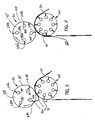
- the supply of vacuum to the vacuum ports such as 218a functions to engage the leading edge of a sheet 30 out of overlapping relationship with the trailing edge of the downstream sheet, as shown in FIG. 8.
- the supply of vacuum to the vacuum ports such as 218a functions to engage the leading edge of a sheet 30 out of overlapping relationship with the trailing edge of the downstream sheet, as shown in FIG. 8.
- spool 140 is positioned so that the activated chamber or passage, such as 200a, enters opening 225 in OFF valve 155.
- this release of vacuum pressure releases engagement of the sheet 30 with the outer surface of count roll 20, so that the folded sheet 30 is release and continues in the path toward folding rolls 90, 95, as shown in FIG. 9.
- the location at which activation or ON vacuum is supplied can be adjusted as desired by rotating the stationary valve body 145. Similarly, the location at which vacuum is cut off can be adjusted by rotation of OFF valve 155. Passages 151a-151d are in axial alignment with each other, which ensures that vacuum actuation occurs at a consistent point in the rotation of spool 140, regardless of which of vacuum inlets 165a-165 is actuated.
- each chamber 200a-d has an available dead time in excess of two hundred-seventy degrees of rotation, during which the chamber can be energized or activated with vacuum pressure.
- count assembly 20 in accordance with the invention will be generally described with reference to an interfolding machine for counting overlapped sheets of material 30 to be interfolded into a stack 32, the application of the count assembly 20 is not so limited.
- the count assembly 20 of the invention could be employed to count a variety of web-materials being fed for a wide variety of uses and is not limiting on the invention.
Landscapes
- Engineering & Computer Science (AREA)
- Mechanical Engineering (AREA)
- Folding Of Thin Sheet-Like Materials, Special Discharging Devices, And Others (AREA)
Applications Claiming Priority (4)
| Application Number | Priority Date | Filing Date | Title |
|---|---|---|---|
| US50858003P | 2003-10-03 | 2003-10-03 | |
| US508580P | 2003-10-03 | ||
| US10/957,006 US7219890B2 (en) | 2003-10-03 | 2004-10-01 | Valve system for the count roll of an interfolding machine |
| US957006 | 2004-10-01 |
Publications (2)
| Publication Number | Publication Date |
|---|---|
| EP1520823A1 true EP1520823A1 (de) | 2005-04-06 |
| EP1520823B1 EP1520823B1 (de) | 2007-02-14 |
Family
ID=34316841
Family Applications (1)
| Application Number | Title | Priority Date | Filing Date |
|---|---|---|---|
| EP04256133A Expired - Lifetime EP1520823B1 (de) | 2003-10-03 | 2004-10-04 | Ventilsystem für die Zählrolle einer Ineinanderfaltmaschine |
Country Status (5)
| Country | Link |
|---|---|
| US (1) | US7219890B2 (de) |
| EP (1) | EP1520823B1 (de) |
| AT (1) | ATE353845T1 (de) |
| DE (1) | DE602004004715T2 (de) |
| ES (1) | ES2281762T3 (de) |
Cited By (1)
| Publication number | Priority date | Publication date | Assignee | Title |
|---|---|---|---|---|
| CN109407486A (zh) * | 2018-12-02 | 2019-03-01 | 中山市迪迈打印科技有限公司 | 计数组件和显影盒 |
Families Citing this family (4)
| Publication number | Priority date | Publication date | Assignee | Title |
|---|---|---|---|---|
| US20120157279A1 (en) * | 2010-12-20 | 2012-06-21 | Uwe Schneider | Process and Apparatus for Joining Flexible Components |
| US9371209B2 (en) | 2012-05-01 | 2016-06-21 | C.G. Bretting Manufacturing Co., Inc. | Single path single web single-fold interfolder and methods |
| US8939445B2 (en) * | 2013-05-30 | 2015-01-27 | Kimberly-Clark Worldwide, Inc. | Vacuum roll with internal rotary valve |
| US10449746B2 (en) | 2016-06-27 | 2019-10-22 | C. G. Bretting Manufacturing Co., Inc. | Web processing system with multiple folding arrangements fed by a single web handling arrangement |
Citations (2)
| Publication number | Priority date | Publication date | Assignee | Title |
|---|---|---|---|---|
| EP1026114A2 (de) * | 1999-01-12 | 2000-08-09 | Green Bay Engineering Corporation | Verfahren und Vorrichtung zur Erzeugung einer Unterbrechung in einem Stapel von ineinandergefalteten Blättern |
| EP1371593A2 (de) * | 2002-06-10 | 2003-12-17 | FPNA Acquisition Corporation | Verfahren und Vorrichtung zur Unterbrechung von ineinandergefalteten Blättern |
Family Cites Families (4)
| Publication number | Priority date | Publication date | Assignee | Title |
|---|---|---|---|---|
| US4838982A (en) * | 1987-06-26 | 1989-06-13 | H.G. Weber & Co., Inc. | Patch applicator vacuum cylinder for web material |
| DE4315549C2 (de) * | 1993-05-10 | 2003-11-20 | Heidelberger Druckmasch Ag | Einrichtung zur Saugluftsteuerung für eine Bogenübergabetrommel |
| DE19958134C2 (de) * | 1999-12-02 | 2003-05-15 | Koenig & Bauer Ag | Saugwalze |
| CA2392429C (en) * | 2001-07-23 | 2006-10-10 | Mitsubishi Heavy Industries, Ltd. | Sheet-fed press and intermediate cylinder for sheet-fed press |
-
2004
- 2004-10-01 US US10/957,006 patent/US7219890B2/en not_active Expired - Fee Related
- 2004-10-04 AT AT04256133T patent/ATE353845T1/de not_active IP Right Cessation
- 2004-10-04 ES ES04256133T patent/ES2281762T3/es not_active Expired - Lifetime
- 2004-10-04 EP EP04256133A patent/EP1520823B1/de not_active Expired - Lifetime
- 2004-10-04 DE DE602004004715T patent/DE602004004715T2/de not_active Expired - Lifetime
Patent Citations (2)
| Publication number | Priority date | Publication date | Assignee | Title |
|---|---|---|---|---|
| EP1026114A2 (de) * | 1999-01-12 | 2000-08-09 | Green Bay Engineering Corporation | Verfahren und Vorrichtung zur Erzeugung einer Unterbrechung in einem Stapel von ineinandergefalteten Blättern |
| EP1371593A2 (de) * | 2002-06-10 | 2003-12-17 | FPNA Acquisition Corporation | Verfahren und Vorrichtung zur Unterbrechung von ineinandergefalteten Blättern |
Cited By (1)
| Publication number | Priority date | Publication date | Assignee | Title |
|---|---|---|---|---|
| CN109407486A (zh) * | 2018-12-02 | 2019-03-01 | 中山市迪迈打印科技有限公司 | 计数组件和显影盒 |
Also Published As
| Publication number | Publication date |
|---|---|
| US20050073089A1 (en) | 2005-04-07 |
| EP1520823B1 (de) | 2007-02-14 |
| US7219890B2 (en) | 2007-05-22 |
| DE602004004715T2 (de) | 2007-10-25 |
| ATE353845T1 (de) | 2007-03-15 |
| ES2281762T3 (es) | 2007-10-01 |
| DE602004004715D1 (de) | 2007-03-29 |
Similar Documents
| Publication | Publication Date | Title |
|---|---|---|
| US4070014A (en) | Web folding apparatus | |
| US5241907A (en) | Sheet transport drum with sheet suction holding surface | |
| EP2955140B1 (de) | Bandhandhabungszylinder, und verfahren zum übergeben eines bogens einer bahn von einem ersten bandhandhabungszylinder zu einem zweiten bandhandhabungszylinder | |
| US5494270A (en) | Cross folder and method of cross folding | |
| EP1520822B1 (de) | Verfahren und Vorrichtung für das Überlappung von Bogen | |
| EP1457444B2 (de) | Maschine zum Ineinanderfalten einer Bahn oder von Blättern mit einer Vakuumtransportwalze | |
| EP1943092B1 (de) | Hochgeschwindigkeitsinterfalzmaschine | |
| EP3475204B1 (de) | Bahnmaterialverarbeitungssystem mit mehreren faltanordnungen und zuführung durch eine einzelne bahnmaterialhandhabungsanordnung | |
| EP1520823B1 (de) | Ventilsystem für die Zählrolle einer Ineinanderfaltmaschine | |
| EP2394942B1 (de) | Einzelfaltineinanderfaltmaschine mit der Möglichkeit von ausgefalteten Handtücher- oder Gewebeprodukten | |
| CA2484888C (en) | High volume adjustable vacuum assembly for a roll in an interfolding machine | |
| JPH0326620A (ja) | 給紙機構 | |
| WO2001016009A1 (en) | System and method for producing folded articles | |
| CA2624701A1 (en) | Interfolder with pre-forming transfer roll | |
| CA2483955C (en) | Valve system for the count roll of an interfolding machine | |
| EP1520820B1 (de) | Vorrichtung und Verfahren für das Ergreifen von Bogen in einer Faltmaschine | |
| EP0322186A2 (de) | Apparat und Verfahren zum Falzen | |
| EP1520821A1 (de) | Vorrichtung und Verfahren zur Schmutzvermeidung um ein Schwert einer Falzmaschine | |
| EP1520819A1 (de) | Selbstzentrierendes Falzschwert eines Falzzylinders | |
| JPH0631898A (ja) | 輪転印刷機の折りたたみ装置中の、刷り本案内胴の間で刷り本を案内する装置 | |
| CA2483175C (en) | Method of and assembly for lapping consecutive sheets of web material | |
| US6440053B1 (en) | Apparatus for folding pluralities of product webs advancing along parallel paths | |
| JPH0718683Y2 (ja) | 輪転印刷機の折機 | |
| JPH0967055A (ja) | 枚葉印刷機の排紙部真空吸引車 | |
| JP2514826Y2 (ja) | 輪転印刷機の折丁分配装置 |
Legal Events
| Date | Code | Title | Description |
|---|---|---|---|
| PUAI | Public reference made under article 153(3) epc to a published international application that has entered the european phase |
Free format text: ORIGINAL CODE: 0009012 |
|
| AK | Designated contracting states |
Kind code of ref document: A1 Designated state(s): AT BE BG CH CY CZ DE DK EE ES FI FR GB GR HU IE IT LI LU MC NL PL PT RO SE SI SK TR |
|
| AX | Request for extension of the european patent |
Extension state: AL HR LT LV MK |
|
| 17P | Request for examination filed |
Effective date: 20051003 |
|
| AKX | Designation fees paid |
Designated state(s): AT BE BG CH CY CZ DE DK EE ES FI FR GB GR HU IE IT LI LU MC NL PL PT RO SE SI SK TR |
|
| GRAP | Despatch of communication of intention to grant a patent |
Free format text: ORIGINAL CODE: EPIDOSNIGR1 |
|
| RTI1 | Title (correction) |
Free format text: VALVE SYSTEM FOR THE COUNT ROLL OF AN INTERFOLDING MACHINE |
|
| GRAS | Grant fee paid |
Free format text: ORIGINAL CODE: EPIDOSNIGR3 |
|
| GRAA | (expected) grant |
Free format text: ORIGINAL CODE: 0009210 |
|
| AK | Designated contracting states |
Kind code of ref document: B1 Designated state(s): AT BE BG CH CY CZ DE DK EE ES FI FR GB GR HU IE IT LI LU MC NL PL PT RO SE SI SK TR |
|
| PG25 | Lapsed in a contracting state [announced via postgrant information from national office to epo] |
Ref country code: LI Free format text: LAPSE BECAUSE OF FAILURE TO SUBMIT A TRANSLATION OF THE DESCRIPTION OR TO PAY THE FEE WITHIN THE PRESCRIBED TIME-LIMIT Effective date: 20070214 Ref country code: PL Free format text: LAPSE BECAUSE OF FAILURE TO SUBMIT A TRANSLATION OF THE DESCRIPTION OR TO PAY THE FEE WITHIN THE PRESCRIBED TIME-LIMIT Effective date: 20070214 Ref country code: AT Free format text: LAPSE BECAUSE OF FAILURE TO SUBMIT A TRANSLATION OF THE DESCRIPTION OR TO PAY THE FEE WITHIN THE PRESCRIBED TIME-LIMIT Effective date: 20070214 Ref country code: CH Free format text: LAPSE BECAUSE OF FAILURE TO SUBMIT A TRANSLATION OF THE DESCRIPTION OR TO PAY THE FEE WITHIN THE PRESCRIBED TIME-LIMIT Effective date: 20070214 Ref country code: DK Free format text: LAPSE BECAUSE OF FAILURE TO SUBMIT A TRANSLATION OF THE DESCRIPTION OR TO PAY THE FEE WITHIN THE PRESCRIBED TIME-LIMIT Effective date: 20070214 Ref country code: FI Free format text: LAPSE BECAUSE OF FAILURE TO SUBMIT A TRANSLATION OF THE DESCRIPTION OR TO PAY THE FEE WITHIN THE PRESCRIBED TIME-LIMIT Effective date: 20070214 Ref country code: NL Free format text: LAPSE BECAUSE OF FAILURE TO SUBMIT A TRANSLATION OF THE DESCRIPTION OR TO PAY THE FEE WITHIN THE PRESCRIBED TIME-LIMIT Effective date: 20070214 Ref country code: BE Free format text: LAPSE BECAUSE OF FAILURE TO SUBMIT A TRANSLATION OF THE DESCRIPTION OR TO PAY THE FEE WITHIN THE PRESCRIBED TIME-LIMIT Effective date: 20070214 Ref country code: SI Free format text: LAPSE BECAUSE OF FAILURE TO SUBMIT A TRANSLATION OF THE DESCRIPTION OR TO PAY THE FEE WITHIN THE PRESCRIBED TIME-LIMIT Effective date: 20070214 |
|
| REG | Reference to a national code |
Ref country code: GB Ref legal event code: FG4D |
|
| REG | Reference to a national code |
Ref country code: CH Ref legal event code: EP |
|
| REF | Corresponds to: |
Ref document number: 602004004715 Country of ref document: DE Date of ref document: 20070329 Kind code of ref document: P |
|
| RAP2 | Party data changed (patent owner data changed or rights of a patent transferred) |
Owner name: FPNA ACQUISITION CORPORATION |
|
| REG | Reference to a national code |
Ref country code: IE Ref legal event code: FG4D |
|
| PG25 | Lapsed in a contracting state [announced via postgrant information from national office to epo] |
Ref country code: SE Free format text: LAPSE BECAUSE OF FAILURE TO SUBMIT A TRANSLATION OF THE DESCRIPTION OR TO PAY THE FEE WITHIN THE PRESCRIBED TIME-LIMIT Effective date: 20070514 |
|
| PG25 | Lapsed in a contracting state [announced via postgrant information from national office to epo] |
Ref country code: BG Free format text: LAPSE BECAUSE OF FAILURE TO SUBMIT A TRANSLATION OF THE DESCRIPTION OR TO PAY THE FEE WITHIN THE PRESCRIBED TIME-LIMIT Effective date: 20070515 |
|
| NLT2 | Nl: modifications (of names), taken from the european patent patent bulletin |
Owner name: FPNA ACQUISITION CORPORATION Effective date: 20070404 |
|
| PG25 | Lapsed in a contracting state [announced via postgrant information from national office to epo] |
Ref country code: PT Free format text: LAPSE BECAUSE OF FAILURE TO SUBMIT A TRANSLATION OF THE DESCRIPTION OR TO PAY THE FEE WITHIN THE PRESCRIBED TIME-LIMIT Effective date: 20070716 |
|
| NLV1 | Nl: lapsed or annulled due to failure to fulfill the requirements of art. 29p and 29m of the patents act | ||
| ET | Fr: translation filed | ||
| REG | Reference to a national code |
Ref country code: CH Ref legal event code: PL |
|
| REG | Reference to a national code |
Ref country code: ES Ref legal event code: FG2A Ref document number: 2281762 Country of ref document: ES Kind code of ref document: T3 |
|
| PG25 | Lapsed in a contracting state [announced via postgrant information from national office to epo] |
Ref country code: SK Free format text: LAPSE BECAUSE OF FAILURE TO SUBMIT A TRANSLATION OF THE DESCRIPTION OR TO PAY THE FEE WITHIN THE PRESCRIBED TIME-LIMIT Effective date: 20070214 |
|
| PLBE | No opposition filed within time limit |
Free format text: ORIGINAL CODE: 0009261 |
|
| STAA | Information on the status of an ep patent application or granted ep patent |
Free format text: STATUS: NO OPPOSITION FILED WITHIN TIME LIMIT |
|
| PG25 | Lapsed in a contracting state [announced via postgrant information from national office to epo] |
Ref country code: CZ Free format text: LAPSE BECAUSE OF FAILURE TO SUBMIT A TRANSLATION OF THE DESCRIPTION OR TO PAY THE FEE WITHIN THE PRESCRIBED TIME-LIMIT Effective date: 20070214 Ref country code: RO Free format text: LAPSE BECAUSE OF FAILURE TO SUBMIT A TRANSLATION OF THE DESCRIPTION OR TO PAY THE FEE WITHIN THE PRESCRIBED TIME-LIMIT Effective date: 20070214 |
|
| 26N | No opposition filed |
Effective date: 20071115 |
|
| PG25 | Lapsed in a contracting state [announced via postgrant information from national office to epo] |
Ref country code: GR Free format text: LAPSE BECAUSE OF FAILURE TO SUBMIT A TRANSLATION OF THE DESCRIPTION OR TO PAY THE FEE WITHIN THE PRESCRIBED TIME-LIMIT Effective date: 20070515 |
|
| PG25 | Lapsed in a contracting state [announced via postgrant information from national office to epo] |
Ref country code: MC Free format text: LAPSE BECAUSE OF NON-PAYMENT OF DUE FEES Effective date: 20071031 |
|
| PG25 | Lapsed in a contracting state [announced via postgrant information from national office to epo] |
Ref country code: IE Free format text: LAPSE BECAUSE OF NON-PAYMENT OF DUE FEES Effective date: 20071004 |
|
| REG | Reference to a national code |
Ref country code: GB Ref legal event code: 732E |
|
| PG25 | Lapsed in a contracting state [announced via postgrant information from national office to epo] |
Ref country code: EE Free format text: LAPSE BECAUSE OF FAILURE TO SUBMIT A TRANSLATION OF THE DESCRIPTION OR TO PAY THE FEE WITHIN THE PRESCRIBED TIME-LIMIT Effective date: 20070214 |
|
| PG25 | Lapsed in a contracting state [announced via postgrant information from national office to epo] |
Ref country code: CY Free format text: LAPSE BECAUSE OF FAILURE TO SUBMIT A TRANSLATION OF THE DESCRIPTION OR TO PAY THE FEE WITHIN THE PRESCRIBED TIME-LIMIT Effective date: 20070214 |
|
| PG25 | Lapsed in a contracting state [announced via postgrant information from national office to epo] |
Ref country code: LU Free format text: LAPSE BECAUSE OF NON-PAYMENT OF DUE FEES Effective date: 20071004 |
|
| REG | Reference to a national code |
Ref country code: FR Ref legal event code: TP |
|
| PG25 | Lapsed in a contracting state [announced via postgrant information from national office to epo] |
Ref country code: HU Free format text: LAPSE BECAUSE OF FAILURE TO SUBMIT A TRANSLATION OF THE DESCRIPTION OR TO PAY THE FEE WITHIN THE PRESCRIBED TIME-LIMIT Effective date: 20070815 Ref country code: TR Free format text: LAPSE BECAUSE OF FAILURE TO SUBMIT A TRANSLATION OF THE DESCRIPTION OR TO PAY THE FEE WITHIN THE PRESCRIBED TIME-LIMIT Effective date: 20070214 |
|
| REG | Reference to a national code |
Ref country code: FR Ref legal event code: PLFP Year of fee payment: 12 |
|
| REG | Reference to a national code |
Ref country code: FR Ref legal event code: PLFP Year of fee payment: 13 |
|
| REG | Reference to a national code |
Ref country code: FR Ref legal event code: PLFP Year of fee payment: 14 |
|
| REG | Reference to a national code |
Ref country code: FR Ref legal event code: PLFP Year of fee payment: 15 |
|
| PGFP | Annual fee paid to national office [announced via postgrant information from national office to epo] |
Ref country code: ES Payment date: 20181127 Year of fee payment: 15 Ref country code: GB Payment date: 20181031 Year of fee payment: 15 |
|
| PGFP | Annual fee paid to national office [announced via postgrant information from national office to epo] |
Ref country code: DE Payment date: 20181228 Year of fee payment: 15 |
|
| REG | Reference to a national code |
Ref country code: DE Ref legal event code: R119 Ref document number: 602004004715 Country of ref document: DE |
|
| PG25 | Lapsed in a contracting state [announced via postgrant information from national office to epo] |
Ref country code: DE Free format text: LAPSE BECAUSE OF NON-PAYMENT OF DUE FEES Effective date: 20200501 |
|
| GBPC | Gb: european patent ceased through non-payment of renewal fee |
Effective date: 20191004 |
|
| PG25 | Lapsed in a contracting state [announced via postgrant information from national office to epo] |
Ref country code: GB Free format text: LAPSE BECAUSE OF NON-PAYMENT OF DUE FEES Effective date: 20191004 Ref country code: FR Free format text: LAPSE BECAUSE OF NON-PAYMENT OF DUE FEES Effective date: 20191031 |
|
| PGFP | Annual fee paid to national office [announced via postgrant information from national office to epo] |
Ref country code: IT Payment date: 20201022 Year of fee payment: 17 |
|
| REG | Reference to a national code |
Ref country code: ES Ref legal event code: FD2A Effective date: 20210226 |
|
| PG25 | Lapsed in a contracting state [announced via postgrant information from national office to epo] |
Ref country code: ES Free format text: LAPSE BECAUSE OF NON-PAYMENT OF DUE FEES Effective date: 20191005 |
|
| PG25 | Lapsed in a contracting state [announced via postgrant information from national office to epo] |
Ref country code: IT Free format text: LAPSE BECAUSE OF NON-PAYMENT OF DUE FEES Effective date: 20211004 |