EP1520954B1 - Türflügel - Google Patents
Türflügel Download PDFInfo
- Publication number
- EP1520954B1 EP1520954B1 EP04019109A EP04019109A EP1520954B1 EP 1520954 B1 EP1520954 B1 EP 1520954B1 EP 04019109 A EP04019109 A EP 04019109A EP 04019109 A EP04019109 A EP 04019109A EP 1520954 B1 EP1520954 B1 EP 1520954B1
- Authority
- EP
- European Patent Office
- Prior art keywords
- door
- rabbet
- shell
- blocks
- shoulder
- Prior art date
- Legal status (The legal status is an assumption and is not a legal conclusion. Google has not performed a legal analysis and makes no representation as to the accuracy of the status listed.)
- Expired - Lifetime
Links
- 229910000831 Steel Inorganic materials 0.000 claims abstract description 6
- 239000010959 steel Substances 0.000 claims abstract description 6
- 239000000853 adhesive Substances 0.000 claims abstract description 3
- 230000001070 adhesive effect Effects 0.000 claims abstract description 3
- 230000003014 reinforcing effect Effects 0.000 claims description 17
- 239000000463 material Substances 0.000 claims description 12
- 238000005452 bending Methods 0.000 claims 2
- 238000005266 casting Methods 0.000 claims 1
- 230000002787 reinforcement Effects 0.000 abstract 3
- 229910052751 metal Inorganic materials 0.000 description 14
- 239000002184 metal Substances 0.000 description 14
- 238000004382 potting Methods 0.000 description 9
- 230000000694 effects Effects 0.000 description 3
- 229910052782 aluminium Inorganic materials 0.000 description 2
- XAGFODPZIPBFFR-UHFFFAOYSA-N aluminium Chemical compound [Al] XAGFODPZIPBFFR-UHFFFAOYSA-N 0.000 description 2
- 239000006260 foam Substances 0.000 description 2
- 239000011368 organic material Substances 0.000 description 2
- 239000004033 plastic Substances 0.000 description 2
- 239000002023 wood Substances 0.000 description 2
- 238000004873 anchoring Methods 0.000 description 1
- 229910010272 inorganic material Inorganic materials 0.000 description 1
- 239000011147 inorganic material Substances 0.000 description 1
- 238000003466 welding Methods 0.000 description 1
Images


Classifications
-
- E—FIXED CONSTRUCTIONS
- E05—LOCKS; KEYS; WINDOW OR DOOR FITTINGS; SAFES
- E05D—HINGES OR SUSPENSION DEVICES FOR DOORS, WINDOWS OR WINGS
- E05D5/00—Construction of single parts, e.g. the parts for attachment
- E05D5/02—Parts for attachment, e.g. flaps
- E05D5/06—Bent flaps
-
- E—FIXED CONSTRUCTIONS
- E05—LOCKS; KEYS; WINDOW OR DOOR FITTINGS; SAFES
- E05D—HINGES OR SUSPENSION DEVICES FOR DOORS, WINDOWS OR WINGS
- E05D5/00—Construction of single parts, e.g. the parts for attachment
- E05D5/02—Parts for attachment, e.g. flaps
- E05D5/0215—Parts for attachment, e.g. flaps for attachment to profile members or the like
- E05D5/0223—Parts for attachment, e.g. flaps for attachment to profile members or the like with parts, e.g. screws, extending through the profile wall or engaging profile grooves
- E05D5/023—Parts for attachment, e.g. flaps for attachment to profile members or the like with parts, e.g. screws, extending through the profile wall or engaging profile grooves with parts extending through the profile wall
-
- E—FIXED CONSTRUCTIONS
- E06—DOORS, WINDOWS, SHUTTERS, OR ROLLER BLINDS IN GENERAL; LADDERS
- E06B—FIXED OR MOVABLE CLOSURES FOR OPENINGS IN BUILDINGS, VEHICLES, FENCES OR LIKE ENCLOSURES IN GENERAL, e.g. DOORS, WINDOWS, BLINDS, GATES
- E06B3/00—Window sashes, door leaves, or like elements for closing wall or like openings; Layout of fixed or moving closures, e.g. windows in wall or like openings; Features of rigidly-mounted outer frames relating to the mounting of wing frames
- E06B3/70—Door leaves
- E06B3/82—Flush doors, i.e. with completely flat surface
- E06B3/827—Flush doors, i.e. with completely flat surface of metal without an internal frame, e.g. with exterior panels substantially of metal
-
- E—FIXED CONSTRUCTIONS
- E05—LOCKS; KEYS; WINDOW OR DOOR FITTINGS; SAFES
- E05Y—INDEXING SCHEME ASSOCIATED WITH SUBCLASSES E05D AND E05F, RELATING TO CONSTRUCTION ELEMENTS, ELECTRIC CONTROL, POWER SUPPLY, POWER SIGNAL OR TRANSMISSION, USER INTERFACES, MOUNTING OR COUPLING, DETAILS, ACCESSORIES, AUXILIARY OPERATIONS NOT OTHERWISE PROVIDED FOR, APPLICATION THEREOF
- E05Y2600/00—Mounting or coupling arrangements for elements provided for in this subclass
- E05Y2600/50—Mounting methods; Positioning
- E05Y2600/502—Clamping
-
- E—FIXED CONSTRUCTIONS
- E05—LOCKS; KEYS; WINDOW OR DOOR FITTINGS; SAFES
- E05Y—INDEXING SCHEME ASSOCIATED WITH SUBCLASSES E05D AND E05F, RELATING TO CONSTRUCTION ELEMENTS, ELECTRIC CONTROL, POWER SUPPLY, POWER SIGNAL OR TRANSMISSION, USER INTERFACES, MOUNTING OR COUPLING, DETAILS, ACCESSORIES, AUXILIARY OPERATIONS NOT OTHERWISE PROVIDED FOR, APPLICATION THEREOF
- E05Y2900/00—Application of doors, windows, wings or fittings thereof
- E05Y2900/10—Application of doors, windows, wings or fittings thereof for buildings or parts thereof
- E05Y2900/13—Type of wing
- E05Y2900/132—Doors
-
- E—FIXED CONSTRUCTIONS
- E06—DOORS, WINDOWS, SHUTTERS, OR ROLLER BLINDS IN GENERAL; LADDERS
- E06B—FIXED OR MOVABLE CLOSURES FOR OPENINGS IN BUILDINGS, VEHICLES, FENCES OR LIKE ENCLOSURES IN GENERAL, e.g. DOORS, WINDOWS, BLINDS, GATES
- E06B3/00—Window sashes, door leaves, or like elements for closing wall or like openings; Layout of fixed or moving closures, e.g. windows in wall or like openings; Features of rigidly-mounted outer frames relating to the mounting of wing frames
- E06B3/70—Door leaves
- E06B2003/7046—Door leaves with provisions for locks, hinges or other fittings
Definitions
- the invention relates to a door leaf with a door leaf and connected to the door leaf hinge parts of door hinges, wherein the door leaf consists of a box-shaped half-shell made of sheet steel and a sheet metal lid and circumferentially on at least two side surfaces designed as a cavity, by sheet metal forming the half-shell and / or the lid having produced door rebate.
- a reinforcing plate is arranged, which is fastened to a side surface of the half-shell assigned to the door hinges and has a width which extends into the region of the door rebate.
- the hinge parts have angularly shaped hinge tabs which are inserted into notches on the inner side of the Falzinnenseite and secured to the reinforcing plate.
- a door leaf with the features described is made DE 44 08 346 A1 known.
- the door rebate is exposed to considerable forces on the provided with the hinge parts side surface.
- heavy door leaves for example, contain glazing, or door leaves, which are made of thin sheets, deformation or wear of the claimed Mosfalzes especially in the connection area of the door hinges are possible.
- the publication DE 195 25 207 A1 shows a consisting of two half-shells door leaf, on the inside of a fastener for a door hinge is welded. Also with this door leaf there is a risk of deformation in the region of the door rebate. From the DE 1 659 633 A is a door with Door rebate known, wherein in the Mitfalz a metal hollow profile is used, which can be used for attaching door hinges.
- the invention has for its object to effectively stiffen the particularly heavily used door rebate on the provided with hinge parts side surface of the door leaf with simple means.
- the door rebate along the side parts provided with hinge parts at least in the region of notches includes a support core which fills the cross section of the door rebate to the reinforcing sheet and a support surface for in forms the notch used hinge tabs.
- the shape-stabilizing effect of the support core contributes significantly to the fact that the support core is supported on the reinforcing plate serving for fastening the door hinges and / or any insert material inside the door leaf.
- the reinforcing plate / insert material and the adjoining support core, which fills the cross section of the door rebate, together form a dimensionally stable abutment for the door leaf-side hinge flap of a door hinge. In this way results in an effective stiffening of the particularly stressed when handling the door leaf Mosfalzes.
- the support core consists of a strip which has been introduced before the deformation of the door rebate as an insert.
- the strip may for example be made of wood, plastic, aluminum or steel and extend over the entire length of the hinged side surface of the door leaf. Instead of a continuous bar but shorter strips can be used, the effect is limited to the connection area of the door hinges.
- blocks are used as a support core, which are insertable through the notches in the door rabbet and are fixed in the door rebate by a press fit or by an adhesive connection.
- the fixation of the blocks by clamping fit has assembly advantages. Be held by a clamping fit blocks furthermore preferred for door leaves which have to withstand high temperatures as fire doors. Conveniently, the blocks contain a bottom groove which gives the block sufficient elasticity for use as a clamping element.
- the door rebate is formed by a U-shaped reshaped edge portion of the sheet metal lid, which rests end on a molded onto the side surface of the half-shell shoulder.
- the shoulder contains in the region of the notches of the Mosfalzes recesses for receiving the support core forming blocks.
- These may, according to a further advantageous embodiment, comprise a lower-side groove which engages over a lower edge of the recesses introduced into the shoulder. If the half-shell has to improve the dimensional stability of the door rebate to the outside angled edge strips on which the sheet metal cover is attached, a step-shaped design is recommended on the underside of the blocks.
- the underside is designed by a small step so that the blocks in the area in front of the shoulder surface flat against the sheet metal lid and in the area behind the shoulder rest flat on the angled edge strips and support the hinge tab without tilting moment.
- the support core consists of a hardening potting material.
- potting material both organic and inorganic materials come into consideration.
- the use of a hard foam is possible.
- the door leaf comprises a door leaf 1 and hinge parts 2 of door hinges 3 connected to the door leaf, which are arranged on a door frame 4 in a manner known per se.
- the door leaf 1 is made of a box-shaped half-shell 5 made of sheet steel and a metal cover 6 and has circumferentially on at least three side surfaces as a cavity formed by sheet metal deformation of the half-shell 5 and / or the lid 6 door rebate 7.
- only the door rebate 7 along the provided with hinge parts 2 side surface of the door panel 1 is shown. At the terminal portions of the hinge parts 2 of the door rebate 7 is exposed to high stresses during handling of the door.
- a reinforcing plate 8 is arranged, which is attached to the side bands of the half-shell 5 associated with the door hinges 3 and whose width is dimensioned so that the reinforcing plate 8 extends into the region of the door rebate 7.
- the hinged parts 2 connected to the door leaf each have an angularly shaped hinge flap 9 which is inserted into an associated notch on the inside of the folded door 7 and fastened to the reinforcing plate 8.
- a support core 10 is arranged in the door rebate 7 at least in the region of the notch, which fills the cross section of the door rebate 7 to the reinforcing plate 8 and a bearing surface for in the Notched hinge used 9 forms. In the embodiments, different embodiments of the support core 10 are shown.
- blocks 11 are used as a support core, which can be used by the notches in the door rebate 7 and are fixed in the door rebate 7.
- the fixation is effected by a clamping seat.
- the representation in Fig. 1 If one assumes that the blocks 11 for clamping fixation include a lower-side groove 12, which gives the block 11 sufficient elasticity for use as a clamping element.
- Fig. 1 has the box-shaped half-shell 5 of the door leaf outwardly angled edge strips 13, where the metal cover 6 z. B. is fixed by welding points.
- the door rebate 7 is formed by a U-shaped reshaped edge portion of the sheet metal lid 6, the end rests on a formed on the side surface of the half-shell 5 shoulder 14.
- the shoulder 14 contains in the region of the notches of the Mosfalzes 7 each have a recess for receiving the support core forming block 11.
- the lower side groove 12 of the pad 11 engages over a lower edge 15 of the introduced into the shoulder 14 recess.
- the block 11 fills the cross section of the door rebate 7 and is clamped with a clamping fit between the reinforcing plate 8 and the U-shaped edge portion of the sheet metal lid 6.
- the block 11 is fixed in position by the recess in the shoulder 14.
- the side surfaces of the box-shaped half-shell 5 are formed as flat surfaces without support shoulder for the door rebate 7.
- the support core 10 consists of a bar 16 which has been introduced before the forming of the door fold 7 as an insert. It may extend over the entire length of the mitfalzes 7 and be designed as wood, plastic, steel or aluminum strip.
- Fig. 3 If the door has to withstand high temperatures as a fire door, an inorganic mass is used as potting material. If no high demands are placed on the temperature resistance, organic materials, in particular hard foams, can also be used as potting material.
- the representation in Fig. 3 takes it that the sheet metal lid 6 adjacent longitudinal edge of the reinforcing plate 8 is embedded in the cured potting material 17. In functional terms, it is sufficient if only the notches associated with the areas of the door rebate 7 is filled with potting material 17. However, it is also within the scope of the invention to completely fill the door rebate 7 on the lateral surface provided with hinge parts 2 with potting material.
Landscapes
- Engineering & Computer Science (AREA)
- Mechanical Engineering (AREA)
- Civil Engineering (AREA)
- Structural Engineering (AREA)
- Securing Of Glass Panes Or The Like (AREA)
- Wing Frames And Configurations (AREA)
- Special Wing (AREA)
- Hinges (AREA)
- Lock And Its Accessories (AREA)
- Seal Device For Vehicle (AREA)
- Closing And Opening Devices For Wings, And Checks For Wings (AREA)
Description
- Die Erfindung betrifft einen Türflügel mit einem Türblatt und an das Türblatt angeschlossenen Scharnierteilen von Türbändern, wobei das Türblatt aus einer kastenförmigen Halbschale aus Stahlblech und einem Blechdeckel besteht sowie umfangseitig an mindestens zwei Seitenflächen einen als Hohlraum ausgebildeten, durch Blechumformung der Halbschale und/oder des Deckels hergestellten Türfalz aufweist. An der Innenseite der Halbschale ist ein Verstärkungsblech angeordnet, welches an einer den Türbändern zugeordneten Seitenfläche der Halbschale befestigt ist und eine sich bis in den Bereich des Türfalzes erstreckende Breite hat. Die Scharnierteile weisen winkelförmig geformte Bandlappen auf, die in Ausklinkungen an der Falzinnenseite des Türfalzes eingesetzt und an dem Verstärkungsblech befestigt sind.
- Ein Türflügel mit den beschriebenen Merkmalen ist aus
DE 44 08 346 A1 bekannt. Bei der Handhabung der Tür, insbesondere beim Zuschlagen des Türflügels oder beim Schließen des Türflügel gegen einen auf der Scharnierseite wirkenden Widerstand, ist der Türfalz an der mit den Scharnierteilen versehenen Seitenfläche erheblichen Kräften ausgesetzt. Bei schweren Türblättern, die beispielsweise Verglasungen enthalten, oder Türblättern, die aus dünnen Blechen gefertigt werden, sind Deformationen oder Verschleißerscheinungen des beanspruchten Türfalzes vor allem im Anschlussbereich der Türbänder möglich. - Die Druckschrift
DE 195 25 207 A1 zeigt ein aus zwei Halbschalen bestehendes Türblatt, an dem innenseitig ein Befestigungselement für ein Türband angeschweißt ist. Auch bei diesem Türblatt besteht die Gefahr von Deformationen im Bereich des Türfalzes. Aus derDE 1 659 633 A ist ein Türflügel mit Türfalz bekannt, wobei in den Türfalz ein Metallhohlprofil eingesetzt ist, der zur Anbringung von Türbändern genutzt werden kann. - Der Erfindung liegt die Aufgabe zugrunde, den besonders stark beanspruchten Türfalz an der mit Scharnierteilen versehenen Seitenfläche des Türblattes mit einfachen Mitteln wirksam zu versteifen.
- Ausgehend von einem Türflügel mit den eingangs beschriebenen Merkmalen wird die Aufgabe erfindungsgemäß dadurch gelöst, dass der Türfalz entlang der mit Scharnierteilen versehenen Seitenfläche zumindest im Bereich der Ausklinkungen einen Stützkern enthält, der den Querschnitt des Türfalzes bis zu dem Verstärkungsblech ausfüllt und eine Auflagefläche für den in die Ausklinkung eingesetzten Bandlappen bildet. Zur formstabilisierenden Wirkung des Stützkerns trägt wesentlich bei, dass der Stützkern an dem der Befestigung der Türbänder dienenden Verstärkungsblech und/oder etwaigen Einlagematerial innerhalb des Türblatts abgestützt ist. Das Verstärkungsblech/Einlagematerial und der daran anliegende Stützkern, welcher den Querschnitt des Türfalzes ausfüllt, bilden zusammen ein formstabiles Widerlager für den türflügelseitigen Bandlappen eines Türbandes. Auf diese Weise resultiert eine wirkungsvolle Versteifung des bei der Handhabung des Türflügels besonders beanspruchten Türfalzes.
- Für die weitere Ausgestaltung der erfindungsgemäßen Lehre ergeben sich eine Vielzahl von Möglichkeiten. Gemäß einer ersten Ausführungsform der Erfindung besteht der Stützkern aus einer Leiste, die vor der Umformung des Türfalzes als Einlegeteil eingebracht worden ist. Die Leiste kann beispielsweise aus Holz, Kunststoff, Aluminium oder Stahl bestehen und sich über die gesamte Länge der mit Scharnierteilen versehenen Seitenfläche des Türblatts erstrecken. Anstelle einer durchgehenden Leiste können allerdings auch kürzere Leisten eingesetzt werden, deren Wirkung auf den Anschlussbereich der Türbänder beschränkt ist.
- Gemäß einer zweiten, bevorzugten Ausführung der erfindungsgemäßen Lehre werden als Stützkern Klötze verwendet, die durch die Ausklinkungen in den Türfalz einsetzbar sind und in dem Türfalz durch einen Klemmsitz oder durch eine Klebeverbindung fixiert sind. Die Fixierung der Klötze durch Klemmsitz hat montagetechnische Vorteile. Durch einen Klemmsitz gehaltene Klötze werden ferner bevorzugt für Türflügel, die als Feuerschutztüren hohen Temperaturen standhalten müssen. Zweckmäßig enthalten die Klötze eine unterseitige Nut, die dem Klotz eine ausreichende Elastizität zur Verwendung als Klemmelement verleiht.
- Gemäß einer bevorzugten Ausführung der Erfindung wird der Türfalz von einem U-förmig umgeformten Randabschnitt des Blechdeckels gebildet, der endseitig auf einer an der Seitenfläche der Halbschale angeformten Schulter aufliegt. Die Schulter enthält im Bereich der Ausklinkungen des Türfalzes Aussparungen zur Aufnahme der den Stützkern bildenden Klötze. Diese können gemäß einer weiteren vorteilhaften Ausgestaltung eine unterseitige Nut enthalten, welche eine Unterkante der in die Schulter eingebrachten Aussparungen übergreift. Wenn die Halbschale zur Verbesserung der Formstabilität des Türfalzes nach Außen abgewinkelte Randstreifen aufweist, auf denen der Blechdeckel befestigt ist, empfiehlt sich eine stufenförmige Ausbildung an der Unterseite der Klötze. Die Unterseite wird dabei durch eine kleine Stufe so gestaltet, dass die Klötze im Bereich vor der Schulter flächig an den Blechdeckel und im Bereich hinter der Schulter flächig auf dem abgewinkelten Randstreifen aufliegen und den Bandlappen kippmomentfrei stützen.
- Eine weitere alternative Ausgestaltung der erfindungsgemäßen Lehre sieht vor, dass der Stützkern aus einem aushärtenden Vergussmaterial besteht. Als Vergussmaterial kommen sowohl organische als auch anorganische Materialien in Betracht. Auch die Verwendung eines Hartschaumes ist möglich. Zwischen dem Verstärkungsblech und dem Blechdeckel des Türblattes verbleibt zweckmäßig ein Spalt. Dieser kann so bemessen werden, dass ein Teil des Vergussmaterials durch den Spalt hindurchtritt und die Längskante des Verstärkungsbleches in dem aushärtenden Vergussmaterial eingebettet wird. Hierdurch wird ein zusätzlicher Verankerungseffekt erreicht.
- Im Folgenden wird die Erfindung anhand einer lediglich ein Ausführungsbeispiel darstellenden Zeichnung erläutert. Es zeigen schematisch:
- Fig.1
- einen Querschnitt durch einen erfindungsgemäßen Türflügel,
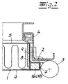
- Fig. 2 u. 3
- weitere Ausgestaltungen des erfindungsgemäßen Türflügels, ebenfalls im Querschnitt.
- Der Türflügel umfasst ein Türblatt 1 und an das Türblatt angeschlossene Scharnierteile 2 von Türbändern 3, die in an sich in bekannter Weise an einer Türzarge 4 angeordnet sind. Das Türblatt 1 ist aus einer kastenförmigen Halbschale 5 aus Stahlblech und einem Blechdeckel 6 gefertigt und weist umfangseitig an mindestens drei Seitenflächen einen als Hohlraum ausgebildeten, durch Blechumformung der Halbschale 5 und/oder des Deckels 6 hergestellten Türfalz 7 auf. In den Ausführungsbeispielen ist lediglich der Türfalz 7 entlang der mit Scharnierteilen 2 versehenen Seitenfläche des Türblatts 1 dargestellt. An den Anschlussbereichen der Scharnierteile 2 ist der Türfalz 7 bei der Handhabung der Tür hohen Beanspruchungen ausgesetzt.
- An der Innenseite der Halbschale 5 ist ein Verstärkungsblech 8 angeordnet, welches an der den Türbändern 3 zugeordneten Seitenfläche der Halbschale 5 befestigt ist und dessen Breite so bemessen ist, dass sich das Verstärkungsblech 8 bis in den Bereich des Türfalzes 7 erstreckt. Die an den Türflügel angeschlossenen Scharnierteile 2 weisen jeweils einen winkelförmig geformten Bandlappen 9 auf, der in eine zugeordnete Ausklinkung an der Falzinnenseite des Türfalzes 7 eingesetzt und an dem Verstärkungsblech 8 befestigt wird. Erfindungsgemäß ist im Türfalz 7 zumindest im Bereich der Ausklinkung ein Stützkern 10 angeordnet, der den Querschnitt des Türfalzes 7 bis zu dem Verstärkungsblech 8 ausfüllt und eine Auflagefläche für den in die Ausklinkung eingesetzten Bandlappen 9 bildet. In den Ausführungsbeispielen sind unterschiedliche Ausgestaltungen des Stützkerns 10 dargestellt.
- Bei der in
Fig. 1 dargestellten, besonders bevorzugten Ausführung werden als Stützkern 10 Klötze 11 verwendet, die durch die Ausklinkungen in den Türfalz 7 einsetzbar sind und in dem Türfalz 7 fixiert sind. Im Ausführungsbeispiel erfolgt die Fixierung durch einen Klemmsitz. Der Darstellung inFig. 1 entnimmt man, dass die Klötze 11 zur Klemmfixierung eine unterseitige Nut 12 enthalten, die dem Klotz 11 eine ausreichende Elastizität zur Verwendung als Klemmelement verleiht. - Im Ausführungsbeispiel der
Fig. 1 weist die kastenförmige Halbschale 5 des Türblattes nach außen abgewinkelte Randstreifen 13 auf, an denen der Blechdeckel 6 z. B. durch Schweißpunkte befestigt ist. Der Türfalz 7 wird von einem U-förmig umgeformten Randabschnitt des Blechdeckels 6 gebildet, der endseitig auf einer an der Seitenfläche der Halbschale 5 angeformten Schulter 14 aufliegt. Die Schulter 14 enthält im Bereich der Ausklinkungen des Türfalzes 7 jeweils eine Aussparung zur Aufnahme des den Stützkern bildenden Klotzes 11. Die unterseitige Nut 12 des Klotzes 11 übergreift dabei eine Unterkante 15 der in die Schulter 14 eingebrachten Aussparung. Der Klotz 11 füllt den Querschnitt des Türfalzes 7 aus und ist mit einem Klemmsitz zwischen dem Verstärkungsblech 8 und dem U-förmig umgeformten Randabschnitt des Blechdeckels 6 eingespannt. In Längsrichtung des Türblattes ist der Klotz 11 durch die Aussparung in der Schulter 14 lagefixiert. Der Darstellung inFig. 1 entnimmt man auch, das die Unterseite des Klotzes 11 stufenförmig so ausgebildet ist, dass der Klotz - von Innen nach Außen betrachtet - im Bereich vor der Schulter flächig an dem Blechdeckel 6 und im Bereich hinter der Schulter 14 flächig auf dem abgewinkelten Randstreifen 13 aufliegt und der Bandlappen 9 kippmomentfrei gestützt wird. - Im Ausführungsbeispiel der
Fig. 2 sind die Seitenflächen der kastenförmigen Halbschale 5 als ebene Flächen ohne Auflageschulter für den Türfalz 7 ausgebildet. Der Stützkern 10 besteht aus einer Leiste 16, die vor der Umformung des Türfalzes 7 als Einlegeteil eingebracht worden ist. Sie kann sich über die gesamte Länge des Türfalzes 7 erstrecken und als Holz-, Kunststoff, Stahl- oder Aluminiumleiste ausgebildet sein. - Im Ausführungsbeispiel der
Fig. 3 besteht der Stützkern 10 aus einem aushärtendem Vergussmaterial 17. Sofern die Tür als Feuerschutztür hohen Temperaturen standhalten muss, wird als Vergussmaterial eine anorganische Masse verwendet. Werden keine hohen Anforderungen an die Temperaturbestänigkeit gestellt, können organische Materialien, insbes. auch Hartschaumstoffe als Vergussmaterial eingesetzt werden. Der Darstellung inFig. 3 entnimmt man, dass die dem Blechdeckel 6 benachbarte Längskante des Verstärkungsbleches 8 in das ausgehärtete Vergussmaterial 17 eingebettet ist. In funktionsmäßiger Hinsicht ist es ausreichend, wenn lediglich die den Ausklinkungen zugeordneten Bereiche des Türfalzes 7 mit Vergussmaterial 17 verfüllt wird. Im Rahmen der Erfindung liegt es aber auch, den Türfalz 7 an der mit Scharnierteilen 2 versehenen Seitenfläche vollständig mit Vergussmaterial zu verfüllen.
Claims (8)
- Türflügel mit einem Türblatt (1) und an das Türblatt angeschlossenen Scharnierteilen (2) von Türbändern (3),
wobei das Türblatt (1) aus einer kastenförmigen Halbschale (5) aus Stahlblech und einem Blechdeckel (6) besteht sowie umfangseitig an mindestens zwei Seitenflächen einen als Hohlraum ausgebildeten, durch Blechumformung der Halbschale und/oder des Deckels hergestellten Türfalz (7) aufweist,
wobei an der Innenseite der Halbschale (5) ein Verstärkungsblech (8) angeordnet ist, welches an einer den Türbändern (3) zugeordneten Seitenfläche der Halbschale (5) befestigt ist und eine sich bis in den Bereich des Türfalzes (7) erstreckende Breite hat, und
wobei die Scharnierteile (2) winkelförmig geformte Bandlappen (9) aufweisen, die in Ausklinkungen an der Falzinnenseite des Türfalzes (7) einsetzt und an dem Verstärkungsblech (8) befestigt sind,
dadurch gekennzeichnet, dass der Türfalz (7) entlang der mit Scharnierteilen (2) versehenen Seitenfläche zumindest im Bereich der Ausklinkungen einen Stützkern (10) enthält, der den Querschnitt des Türfalzes (7) bis zu dem Verstärkungsblech (8) ausfüllt und eine Auflagefläche für den in die Ausklinkung eingesetzten Bandlappen (9) bildet. - Türflügel nach Anspruch 1, dadurch gekennzeichnet, dass der Stützkern (10) aus einer Leiste (16) besteht, die vor der Umformung des Türfalzes (7) als Einlegeteil eingebracht worden ist.
- Türflügel nach Anspruch 1, dadurch gekennzeichnet, dass als Stützkern (10) Klötze (11) verwendet werden, die durch die Ausklinkungen in den Türfalz (7) einsetzbar sind und in dem Türfalz (7) durch einen Klemmsitz oder durch eine Klebeverbindung fixiert sind.
- Türflügel nach Anspruch 3, dadurch gekennzeichnet, dass die Klötze (11) eine unterseitige Nut (12) enthalten, die dem Klotz eine ausreichende Elastizität zur Verwendung als Klemmelement verleiht.
- Türflügel nach Anspruch 3 oder 4, dadurch gekennzeichnet, dass der Türfalz (7) von einem U-förmig umgeformten Randabschnitt des Blechdeckels (6) gebildet wird, der endseitig auf einer an der Seitenfläche der Halbschale (5) angeformten Schulter (14) aufliegt, und dass die Schulter (14) im Bereich der Ausklinkungen des Türfalzes (7) Aussparungen zur Aufnahme der den Stützkern bildenden Klötze (11) enthält.
- Türflügel nach Anspruch 5, dadurch gekennzeichnet, dass die Klötze (11) eine unterseitige Nut (12) enthalten, welche eine Unterkante (15) der in die Schulter (14) eingebrachten Aussparung übergreift.
- Türflügel nach Anspruch 5 oder 6, dadurch gekennzeichnet, dass die kastenförmige Halbschale (5) nach außen abgewinkelte Randstreifen (13) aufweist, an denen der Blechdeckel (6) befestigt ist, und das die Unterseite der Klötze (11) stufenförmig so ausgebildet ist, dass die Klötze (11) im Bereich vor der Schulter (14) flächig an dem Blechdeckel (6) und im Bereich hinter der Schulter (14) flächig auf dem abgewinkelten Randstreifen (13) aufliegen und den Bandlappen (9) kippmoment frei stützen.
- Türflügel nach Anspruch 1, dadurch gekennzeichnet, dass der Stützkern (10) aus einem aushärtendem Vergussmaterial (7) besteht.
Applications Claiming Priority (2)
| Application Number | Priority Date | Filing Date | Title |
|---|---|---|---|
| DE10345870 | 2003-10-01 | ||
| DE10345870A DE10345870B4 (de) | 2003-10-01 | 2003-10-01 | Türflügel |
Publications (2)
| Publication Number | Publication Date |
|---|---|
| EP1520954A1 EP1520954A1 (de) | 2005-04-06 |
| EP1520954B1 true EP1520954B1 (de) | 2008-04-16 |
Family
ID=34306225
Family Applications (1)
| Application Number | Title | Priority Date | Filing Date |
|---|---|---|---|
| EP04019109A Expired - Lifetime EP1520954B1 (de) | 2003-10-01 | 2004-08-12 | Türflügel |
Country Status (3)
| Country | Link |
|---|---|
| EP (1) | EP1520954B1 (de) |
| AT (1) | ATE392528T1 (de) |
| DE (2) | DE10345870B4 (de) |
Families Citing this family (4)
| Publication number | Priority date | Publication date | Assignee | Title |
|---|---|---|---|---|
| US9206700B2 (en) | 2013-10-25 | 2015-12-08 | Siemens Aktiengesellschaft | Outer vane support ring including a strong back plate in a compressor section of a gas turbine engine |
| JP6433741B2 (ja) * | 2014-10-02 | 2018-12-05 | Ykk Ap株式会社 | 部品の取付構造及び建具 |
| CN106593163B (zh) * | 2016-12-25 | 2018-10-09 | 信宜市高新门业有限公司 | 电解板门的合页安装结构 |
| CN109372364A (zh) * | 2018-12-24 | 2019-02-22 | 河北新正消防设备有限公司 | 门扇合页安装结构 |
Family Cites Families (4)
| Publication number | Priority date | Publication date | Assignee | Title |
|---|---|---|---|---|
| DE6606648U (de) * | 1966-03-19 | 1970-11-12 | Ct Pal Ag | Fluegel, insbesondere fuer tueren |
| DE2412692C3 (de) * | 1974-03-16 | 1979-05-03 | Guenter 4772 Bad Sassendorf Langenhorst | Türblatt mit einem umlaufenden Rahmen aus Profilleisten |
| DE4408346A1 (de) * | 1993-11-26 | 1995-06-01 | Riexinger Tuerenwerk | Türflügel für ein Gebäude o. dgl. und Verfahren zum Herstellen eines Türflügels |
| AT403613B (de) * | 1994-07-20 | 1998-04-27 | Sterrer Manfred | Türflügel |
-
2003
- 2003-10-01 DE DE10345870A patent/DE10345870B4/de not_active Expired - Fee Related
-
2004
- 2004-08-12 DE DE502004006829T patent/DE502004006829D1/de not_active Expired - Lifetime
- 2004-08-12 AT AT04019109T patent/ATE392528T1/de not_active IP Right Cessation
- 2004-08-12 EP EP04019109A patent/EP1520954B1/de not_active Expired - Lifetime
Also Published As
| Publication number | Publication date |
|---|---|
| ATE392528T1 (de) | 2008-05-15 |
| DE10345870B4 (de) | 2006-06-08 |
| DE502004006829D1 (de) | 2008-05-29 |
| DE10345870A1 (de) | 2005-04-28 |
| EP1520954A1 (de) | 2005-04-06 |
Similar Documents
| Publication | Publication Date | Title |
|---|---|---|
| EP0236291B1 (de) | Rammschutzträger, insbesondere zur Verstärkung von Kraftfahrzeugtüren | |
| EP0665724A1 (de) | Metallkoffer, sowie verfahren zur herstellung eines metallkoffers | |
| EP2053191A2 (de) | Haustür-Türblatt, damit versehene Haustür und Herstellverfahren dafür | |
| EP0992383B1 (de) | Türsystem für Nutzfahrzeuge | |
| DE3323498C2 (de) | ||
| EP0814228A2 (de) | Verstärkungsprofil für Kunststoff-Hohlprofile zur Herstellung von Fenster, Türen oder dgl. | |
| EP1346879B1 (de) | Einstiegleiste für einen Kraftfahrzeugschweller | |
| EP0716210A2 (de) | Eckverbinder zum Verbinden von Kunststoffprofilen | |
| EP1520954B1 (de) | Türflügel | |
| DE19839268B4 (de) | Gefälzte Kantenverbindung | |
| DE2328829B2 (de) | Rahmenlose Kraftfahrzeugtür, insbesondere Seitentür für Personenkraftwagen | |
| EP0444405A2 (de) | Beschlag für Fenster und Türen | |
| DE19526207C2 (de) | Stahltürblatt | |
| DE4128141C1 (de) | ||
| DE2603828C2 (de) | Verfahren zur Herstellung eines Flügelrahmenstabes für Schwingtore | |
| AT402836B (de) | Halteeinrichtung für platten, insbesondere glasplatten, in ausschnitten von bauteilen | |
| EP4215709A1 (de) | Dichtleiste für einen aus einzelnen rahmenprofilen zusammengesetzten rahmen eines fensters, einer tür oder einer fassade | |
| DE2924442A1 (de) | Zarge fuer fenster und/oder tueren, insbesondere fuer kellerfenster | |
| DE29903324U1 (de) | Rahmen eines Fensters, einer Klappe oder einer Tür an Wohnwagen, Wohnmobilen oder sonstigen Fahrzeugen | |
| CH672000A5 (de) | ||
| DE29618315U1 (de) | Fenster oder Türen mit Verglasung | |
| EP1811112B1 (de) | Scheibenverklebung | |
| EP3719243A1 (de) | T-verbinder, insbesondere sprossenverbinder, für geklebte verglasungen | |
| DE2530976A1 (de) | Fenster, tuer o.dgl. | |
| EP1333144B1 (de) | Tür mit Profilnut |
Legal Events
| Date | Code | Title | Description |
|---|---|---|---|
| PUAI | Public reference made under article 153(3) epc to a published international application that has entered the european phase |
Free format text: ORIGINAL CODE: 0009012 |
|
| AK | Designated contracting states |
Kind code of ref document: A1 Designated state(s): AT BE BG CH CY CZ DE DK EE ES FI FR GB GR HU IE IT LI LU MC NL PL PT RO SE SI SK TR |
|
| AX | Request for extension of the european patent |
Extension state: AL HR LT LV MK |
|
| 17P | Request for examination filed |
Effective date: 20050315 |
|
| AKX | Designation fees paid |
Designated state(s): AT BE BG CH CY CZ DE DK EE ES FI FR GB GR HU IE IT LI LU MC NL PL PT RO SE SI SK TR |
|
| 17Q | First examination report despatched |
Effective date: 20061024 |
|
| GRAP | Despatch of communication of intention to grant a patent |
Free format text: ORIGINAL CODE: EPIDOSNIGR1 |
|
| GRAS | Grant fee paid |
Free format text: ORIGINAL CODE: EPIDOSNIGR3 |
|
| GRAA | (expected) grant |
Free format text: ORIGINAL CODE: 0009210 |
|
| AK | Designated contracting states |
Kind code of ref document: B1 Designated state(s): AT BE BG CH CY CZ DE DK EE ES FI FR GB GR HU IE IT LI LU MC NL PL PT RO SE SI SK TR |
|
| REG | Reference to a national code |
Ref country code: CH Ref legal event code: EP |
|
| REG | Reference to a national code |
Ref country code: IE Ref legal event code: FG4D Free format text: LANGUAGE OF EP DOCUMENT: GERMAN |
|
| REF | Corresponds to: |
Ref document number: 502004006829 Country of ref document: DE Date of ref document: 20080529 Kind code of ref document: P |
|
| PG25 | Lapsed in a contracting state [announced via postgrant information from national office to epo] |
Ref country code: SI Free format text: LAPSE BECAUSE OF FAILURE TO SUBMIT A TRANSLATION OF THE DESCRIPTION OR TO PAY THE FEE WITHIN THE PRESCRIBED TIME-LIMIT Effective date: 20080416 |
|
| NLV1 | Nl: lapsed or annulled due to failure to fulfill the requirements of art. 29p and 29m of the patents act | ||
| PG25 | Lapsed in a contracting state [announced via postgrant information from national office to epo] |
Ref country code: FI Free format text: LAPSE BECAUSE OF FAILURE TO SUBMIT A TRANSLATION OF THE DESCRIPTION OR TO PAY THE FEE WITHIN THE PRESCRIBED TIME-LIMIT Effective date: 20080416 Ref country code: ES Free format text: LAPSE BECAUSE OF FAILURE TO SUBMIT A TRANSLATION OF THE DESCRIPTION OR TO PAY THE FEE WITHIN THE PRESCRIBED TIME-LIMIT Effective date: 20080727 Ref country code: NL Free format text: LAPSE BECAUSE OF FAILURE TO SUBMIT A TRANSLATION OF THE DESCRIPTION OR TO PAY THE FEE WITHIN THE PRESCRIBED TIME-LIMIT Effective date: 20080416 Ref country code: PT Free format text: LAPSE BECAUSE OF FAILURE TO SUBMIT A TRANSLATION OF THE DESCRIPTION OR TO PAY THE FEE WITHIN THE PRESCRIBED TIME-LIMIT Effective date: 20080916 Ref country code: BG Free format text: LAPSE BECAUSE OF FAILURE TO SUBMIT A TRANSLATION OF THE DESCRIPTION OR TO PAY THE FEE WITHIN THE PRESCRIBED TIME-LIMIT Effective date: 20080716 |
|
| PG25 | Lapsed in a contracting state [announced via postgrant information from national office to epo] |
Ref country code: PL Free format text: LAPSE BECAUSE OF FAILURE TO SUBMIT A TRANSLATION OF THE DESCRIPTION OR TO PAY THE FEE WITHIN THE PRESCRIBED TIME-LIMIT Effective date: 20080416 |
|
| REG | Reference to a national code |
Ref country code: IE Ref legal event code: FD4D |
|
| PG25 | Lapsed in a contracting state [announced via postgrant information from national office to epo] |
Ref country code: SE Free format text: LAPSE BECAUSE OF FAILURE TO SUBMIT A TRANSLATION OF THE DESCRIPTION OR TO PAY THE FEE WITHIN THE PRESCRIBED TIME-LIMIT Effective date: 20080716 Ref country code: IE Free format text: LAPSE BECAUSE OF FAILURE TO SUBMIT A TRANSLATION OF THE DESCRIPTION OR TO PAY THE FEE WITHIN THE PRESCRIBED TIME-LIMIT Effective date: 20080416 Ref country code: DK Free format text: LAPSE BECAUSE OF FAILURE TO SUBMIT A TRANSLATION OF THE DESCRIPTION OR TO PAY THE FEE WITHIN THE PRESCRIBED TIME-LIMIT Effective date: 20080416 Ref country code: CZ Free format text: LAPSE BECAUSE OF FAILURE TO SUBMIT A TRANSLATION OF THE DESCRIPTION OR TO PAY THE FEE WITHIN THE PRESCRIBED TIME-LIMIT Effective date: 20080416 |
|
| ET | Fr: translation filed | ||
| PLBE | No opposition filed within time limit |
Free format text: ORIGINAL CODE: 0009261 |
|
| STAA | Information on the status of an ep patent application or granted ep patent |
Free format text: STATUS: NO OPPOSITION FILED WITHIN TIME LIMIT |
|
| PG25 | Lapsed in a contracting state [announced via postgrant information from national office to epo] |
Ref country code: RO Free format text: LAPSE BECAUSE OF FAILURE TO SUBMIT A TRANSLATION OF THE DESCRIPTION OR TO PAY THE FEE WITHIN THE PRESCRIBED TIME-LIMIT Effective date: 20080416 Ref country code: SK Free format text: LAPSE BECAUSE OF FAILURE TO SUBMIT A TRANSLATION OF THE DESCRIPTION OR TO PAY THE FEE WITHIN THE PRESCRIBED TIME-LIMIT Effective date: 20080416 |
|
| 26N | No opposition filed |
Effective date: 20090119 |
|
| PG25 | Lapsed in a contracting state [announced via postgrant information from national office to epo] |
Ref country code: MC Free format text: LAPSE BECAUSE OF NON-PAYMENT OF DUE FEES Effective date: 20080831 |
|
| REG | Reference to a national code |
Ref country code: CH Ref legal event code: PL |
|
| GBPC | Gb: european patent ceased through non-payment of renewal fee |
Effective date: 20080812 |
|
| PG25 | Lapsed in a contracting state [announced via postgrant information from national office to epo] |
Ref country code: EE Free format text: LAPSE BECAUSE OF FAILURE TO SUBMIT A TRANSLATION OF THE DESCRIPTION OR TO PAY THE FEE WITHIN THE PRESCRIBED TIME-LIMIT Effective date: 20080416 |
|
| PG25 | Lapsed in a contracting state [announced via postgrant information from national office to epo] |
Ref country code: LI Free format text: LAPSE BECAUSE OF NON-PAYMENT OF DUE FEES Effective date: 20080831 Ref country code: CH Free format text: LAPSE BECAUSE OF NON-PAYMENT OF DUE FEES Effective date: 20080831 |
|
| PG25 | Lapsed in a contracting state [announced via postgrant information from national office to epo] |
Ref country code: BE Free format text: LAPSE BECAUSE OF NON-PAYMENT OF DUE FEES Effective date: 20080831 |
|
| PG25 | Lapsed in a contracting state [announced via postgrant information from national office to epo] |
Ref country code: CY Free format text: LAPSE BECAUSE OF FAILURE TO SUBMIT A TRANSLATION OF THE DESCRIPTION OR TO PAY THE FEE WITHIN THE PRESCRIBED TIME-LIMIT Effective date: 20080416 |
|
| PG25 | Lapsed in a contracting state [announced via postgrant information from national office to epo] |
Ref country code: AT Free format text: LAPSE BECAUSE OF NON-PAYMENT OF DUE FEES Effective date: 20080812 |
|
| PG25 | Lapsed in a contracting state [announced via postgrant information from national office to epo] |
Ref country code: GB Free format text: LAPSE BECAUSE OF NON-PAYMENT OF DUE FEES Effective date: 20080812 |
|
| PG25 | Lapsed in a contracting state [announced via postgrant information from national office to epo] |
Ref country code: LU Free format text: LAPSE BECAUSE OF NON-PAYMENT OF DUE FEES Effective date: 20080812 Ref country code: HU Free format text: LAPSE BECAUSE OF FAILURE TO SUBMIT A TRANSLATION OF THE DESCRIPTION OR TO PAY THE FEE WITHIN THE PRESCRIBED TIME-LIMIT Effective date: 20081017 |
|
| PG25 | Lapsed in a contracting state [announced via postgrant information from national office to epo] |
Ref country code: TR Free format text: LAPSE BECAUSE OF FAILURE TO SUBMIT A TRANSLATION OF THE DESCRIPTION OR TO PAY THE FEE WITHIN THE PRESCRIBED TIME-LIMIT Effective date: 20080416 |
|
| PG25 | Lapsed in a contracting state [announced via postgrant information from national office to epo] |
Ref country code: GR Free format text: LAPSE BECAUSE OF NON-PAYMENT OF DUE FEES Effective date: 20080831 |
|
| PGFP | Annual fee paid to national office [announced via postgrant information from national office to epo] |
Ref country code: DE Payment date: 20140806 Year of fee payment: 11 |
|
| PGFP | Annual fee paid to national office [announced via postgrant information from national office to epo] |
Ref country code: FR Payment date: 20140821 Year of fee payment: 11 |
|
| PGFP | Annual fee paid to national office [announced via postgrant information from national office to epo] |
Ref country code: IT Payment date: 20140827 Year of fee payment: 11 |
|
| REG | Reference to a national code |
Ref country code: DE Ref legal event code: R119 Ref document number: 502004006829 Country of ref document: DE |
|
| PG25 | Lapsed in a contracting state [announced via postgrant information from national office to epo] |
Ref country code: IT Free format text: LAPSE BECAUSE OF NON-PAYMENT OF DUE FEES Effective date: 20150812 |
|
| REG | Reference to a national code |
Ref country code: FR Ref legal event code: ST Effective date: 20160429 |
|
| PG25 | Lapsed in a contracting state [announced via postgrant information from national office to epo] |
Ref country code: DE Free format text: LAPSE BECAUSE OF NON-PAYMENT OF DUE FEES Effective date: 20160301 |
|
| PG25 | Lapsed in a contracting state [announced via postgrant information from national office to epo] |
Ref country code: FR Free format text: LAPSE BECAUSE OF NON-PAYMENT OF DUE FEES Effective date: 20150831 |