EP1520966A2 - Verfahren zur Steuerung einer aufgeladenen Brennkraftmaschine und entsprechende Brennkraftmaschine - Google Patents
Verfahren zur Steuerung einer aufgeladenen Brennkraftmaschine und entsprechende Brennkraftmaschine Download PDFInfo
- Publication number
- EP1520966A2 EP1520966A2 EP04292324A EP04292324A EP1520966A2 EP 1520966 A2 EP1520966 A2 EP 1520966A2 EP 04292324 A EP04292324 A EP 04292324A EP 04292324 A EP04292324 A EP 04292324A EP 1520966 A2 EP1520966 A2 EP 1520966A2
- Authority
- EP
- European Patent Office
- Prior art keywords
- exhaust
- opening
- exhaust valve
- instant
- process according
- Prior art date
- Legal status (The legal status is an assumption and is not a legal conclusion. Google has not performed a legal analysis and makes no representation as to the accuracy of the status listed.)
- Withdrawn
Links
- 238000000034 method Methods 0.000 title claims abstract description 61
- 238000002485 combustion reaction Methods 0.000 claims abstract description 13
- 239000007789 gas Substances 0.000 claims description 11
- 230000007935 neutral effect Effects 0.000 claims 1
- 238000010586 diagram Methods 0.000 description 3
- 239000000446 fuel Substances 0.000 description 2
- 230000001133 acceleration Effects 0.000 description 1
- 239000003054 catalyst Substances 0.000 description 1
- 230000006835 compression Effects 0.000 description 1
- 238000007906 compression Methods 0.000 description 1
- 230000000063 preceeding effect Effects 0.000 description 1
- 230000037452 priming Effects 0.000 description 1
- 230000035484 reaction time Effects 0.000 description 1
- 230000004044 response Effects 0.000 description 1
Images


Classifications
-
- F—MECHANICAL ENGINEERING; LIGHTING; HEATING; WEAPONS; BLASTING
- F02—COMBUSTION ENGINES; HOT-GAS OR COMBUSTION-PRODUCT ENGINE PLANTS
- F02D—CONTROLLING COMBUSTION ENGINES
- F02D41/00—Electrical control of supply of combustible mixture or its constituents
- F02D41/0002—Controlling intake air
- F02D41/0007—Controlling intake air for control of turbo-charged or super-charged engines
-
- F—MECHANICAL ENGINEERING; LIGHTING; HEATING; WEAPONS; BLASTING
- F01—MACHINES OR ENGINES IN GENERAL; ENGINE PLANTS IN GENERAL; STEAM ENGINES
- F01L—CYCLICALLY OPERATING VALVES FOR MACHINES OR ENGINES
- F01L1/00—Valve-gear or valve arrangements, e.g. lift-valve gear
- F01L1/26—Valve-gear or valve arrangements, e.g. lift-valve gear characterised by the provision of two or more valves operated simultaneously by same transmitting-gear; peculiar to machines or engines with more than two lift-valves per cylinder
-
- F—MECHANICAL ENGINEERING; LIGHTING; HEATING; WEAPONS; BLASTING
- F01—MACHINES OR ENGINES IN GENERAL; ENGINE PLANTS IN GENERAL; STEAM ENGINES
- F01L—CYCLICALLY OPERATING VALVES FOR MACHINES OR ENGINES
- F01L1/00—Valve-gear or valve arrangements, e.g. lift-valve gear
- F01L1/34—Valve-gear or valve arrangements, e.g. lift-valve gear characterised by the provision of means for changing the timing of the valves without changing the duration of opening and without affecting the magnitude of the valve lift
-
- F—MECHANICAL ENGINEERING; LIGHTING; HEATING; WEAPONS; BLASTING
- F01—MACHINES OR ENGINES IN GENERAL; ENGINE PLANTS IN GENERAL; STEAM ENGINES
- F01L—CYCLICALLY OPERATING VALVES FOR MACHINES OR ENGINES
- F01L9/00—Valve-gear or valve arrangements actuated non-mechanically
- F01L9/20—Valve-gear or valve arrangements actuated non-mechanically by electric means
-
- F—MECHANICAL ENGINEERING; LIGHTING; HEATING; WEAPONS; BLASTING
- F02—COMBUSTION ENGINES; HOT-GAS OR COMBUSTION-PRODUCT ENGINE PLANTS
- F02B—INTERNAL-COMBUSTION PISTON ENGINES; COMBUSTION ENGINES IN GENERAL
- F02B29/00—Engines characterised by provision for charging or scavenging not provided for in groups F02B25/00, F02B27/00 or F02B33/00 - F02B39/00; Details thereof
- F02B29/08—Modifying distribution valve timing for charging purposes
-
- F—MECHANICAL ENGINEERING; LIGHTING; HEATING; WEAPONS; BLASTING
- F02—COMBUSTION ENGINES; HOT-GAS OR COMBUSTION-PRODUCT ENGINE PLANTS
- F02D—CONTROLLING COMBUSTION ENGINES
- F02D41/00—Electrical control of supply of combustible mixture or its constituents
- F02D41/0002—Controlling intake air
- F02D2041/001—Controlling intake air for engines with variable valve actuation
-
- F—MECHANICAL ENGINEERING; LIGHTING; HEATING; WEAPONS; BLASTING
- F02—COMBUSTION ENGINES; HOT-GAS OR COMBUSTION-PRODUCT ENGINE PLANTS
- F02D—CONTROLLING COMBUSTION ENGINES
- F02D41/00—Electrical control of supply of combustible mixture or its constituents
- F02D41/02—Circuit arrangements for generating control signals
- F02D41/04—Introducing corrections for particular operating conditions
- F02D41/10—Introducing corrections for particular operating conditions for acceleration
-
- Y—GENERAL TAGGING OF NEW TECHNOLOGICAL DEVELOPMENTS; GENERAL TAGGING OF CROSS-SECTIONAL TECHNOLOGIES SPANNING OVER SEVERAL SECTIONS OF THE IPC; TECHNICAL SUBJECTS COVERED BY FORMER USPC CROSS-REFERENCE ART COLLECTIONS [XRACs] AND DIGESTS
- Y02—TECHNOLOGIES OR APPLICATIONS FOR MITIGATION OR ADAPTATION AGAINST CLIMATE CHANGE
- Y02T—CLIMATE CHANGE MITIGATION TECHNOLOGIES RELATED TO TRANSPORTATION
- Y02T10/00—Road transport of goods or passengers
- Y02T10/10—Internal combustion engine [ICE] based vehicles
- Y02T10/12—Improving ICE efficiencies
Definitions
- the present invention relates to a method of control of an internal combustion engine having at least one cylinder provided with at least one exhaust valve and a moving piston between a bottom dead center and a top dead center and can be supercharged by at least one turbocharger driven by the exhaust gases of the cylinder, of the type comprising, during an elementary escape cycle, a first step of escape between a first moment opening and a first closing moment of at least an exhaust valve.
- Document FR-A-2,581,424 describes a motor with internal combustion having a turbocharger powered by engine exhaust and adapted to compress the intake air flow from the engine.
- This document further describes a control method the engine to spread over time the peaks of gas pressure arriving at the turbocharger from the different cylinders.
- the turbocharger When the driver asks for a strong acceleration, the turbocharger requires a time of response due to the time required to bring the turbine.
- the invention aims to overcome this disadvantage and to propose a control method that allows a setting in fast action turbocharger.
- the subject of the invention is a method of aforementioned type, characterized in that it comprises at least one second step of escape, during the same cycle elementary exhaust, corresponding to a second opening moment and a second closing time of at minus an exhaust valve.
- the invention furthermore relates to a motor with internal combustion comprising a cylinder provided with at least an exhaust valve and a turbocharger, the engine further comprising valve control means exhaust system, characterized in that the control means are adapted to implement a method as described above.
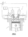
- the motor part M shown in Figure 1 essentially comprises a cylinder 1 and a cylinder head 3 capping said cylinder, in which are formed, a part, an intake duct 5 and, on the other hand, a duct exhaust 7.
- the engine M is an internal combustion engine, so a spark ignition engine or an engine diesel.
- the piston 9 is mobile between a top dead center and a bottom dead center.
- the represented motor part furthermore comprises an intake valve 25 and an exhaust valve 27, associated with the cylinder 1, and controlled by actuators respective ones 29, 31 so as to selectively close off or releasing respectively the inlet 15 and the orifice exhaust 17.
- the motor part represented, associated with the cylinder 1, further comprises a fuel injector 33, arranged to inject fuel in a controlled manner electronically in the intake duct 5.
- the engine M further comprises a turbocharger T connected, on the one hand, to the exhaust duct 7 to be driven by the exhaust gases circulating in the pipe 7 and, on the other hand, to the inlet duct 5 for compress the intake air flowing in line 5.
- the control of the actuators 29, 31 and the injector 33 is provided by an electronic control and order 40.
- FIGs in Figures 2 and 4 to 9 show the opening and closing phases of the valves exhaust.
- the phases of operation of the exhaust valves will be represented by the state ⁇ over time intervals t corresponding to rotation angle ranges ⁇ of the crankshaft.
- the figures also show low dead spots PMB and high PMH of the piston 9.
- Figures 2 and 9 are further illustrated the appearance of the pressure pc in the cylinder 1 and the pressure pe in the exhaust duct as a function of time t .
- a cycle of operation of the cylinder 1 comprises at least one admission step, not shown, during which the inlet valve 25 is open.
- the admission stage is essentially between a top dead center TDC and the bottom dead center according to PMB piston 9.
- the intake valve is in the closed state at least between a bottom dead center PMB and the next top dead center PMH of the piston.
- the method according to the invention comprises a first escape step E1, constituting the initial step exhaust.
- This step E1 is defined by a first opening moment OE1 and by a first moment of closing FE1 of the exhaust valve 27.
- the method includes a second E2 escape step or step terminal, defined by a second opening instant OE2 and a second closing time FE2 of the valve 27.
- second opening moment OE2 is located after the first closing time FE1.
- a closing interval I1 in which the Exhaust valve 27 is closed.
- the method according to the invention therefore creates waves of pressure by a change in the flow of exhaust flowing through the valve.
- the first opening instant OE1 is located before the bottom dead center PMB of the piston 9 and the first moment of closing FE1 is located near the mid-race between PMB and TDC.
- the second closing moment FE2 is located after the dead point high PMH.
- the pressure pc prevailing in the cylinder 1 drops to a pressure pc 0 and a first peak of pressure pe 1 occurs in the exhaust pipe 7 by the decrease in volume induced by the piston 9 moving towards the top dead center TDC.
- the pressure Pc in the cylinder 1 increases due to the rise of the piston 9.
- the pressure Pc in the cylinder 1 and drop occurs a second peak pressure pe 2 in the exhaust pipe 7.
- the pressure pe 2 is lower than the pressure pe 1 of the first peak.
- the method according to the invention therefore creates waves of pressure by a change in the flow of exhaust flowing through the exhaust valve 27.
- the exhaust gas having a pressure high its temperature is also high. Consequently, during a cold start of the engine M, the priming time a catalyst, possibly present in the pipe exhaust 7 is weak.
- the first opening instant OE1 is located after the bottom dead center PMB. So, between the point death low PMB and the opening moment OE1, the piston 9 recompresses the gas enclosed in the cylinder 1, so that the pressure prevailing in cylinder 1 when opening of the valve 27 is important.
- Figure 3 schematically shows a part of a variant of an engine.
- the motor shown in Figure 3 differs from motor of Figure 1 in that two orifices are provided exhaust 17-1, 17-2 communicating with two ducts 7-1, 7-2 respectively, which extend separately to a joint in a common exhaust pipe 7.
- the two exhaust ports 17-1, 17-2 are associated with two respective exhaust valves 27-1, 27-2 to be moved independently.
- the valves 27-1, 27-2 are moved simultaneously, so that the two valves 27-1, 27-2 and the two orifices exhaust 17-1, 17-2 can be considered as a together a single exhaust valve and an orifice single exhaust, as shown in Figure 1.
- Figure 4 shows a mode of implementation of process that can only be used with the engine of the Figure 3 and this only when valves 27-1, 27-2 are operated independently.
- first escape step E1 is defined by first moments of opening OE1 and closure FE1 of the valve 27-1.
- the second escape step E2 is defined by second opening times OE2 and closing FE2 of the second exhaust valve 27-2.
- first closing moment FE1 is located after the second opening time OE2.
- This method therefore comprises a overlap interval C1 of the two steps E1 and E2, during which the two valves 27-1, 27-2 are open.
- the moment of closure FE1 is located near the mid-race piston 9 between low dead spots PMB and high PMH. More precisely, the moments of opening OE1 and closure FE1 can be within a range of more than or 20 months degrees of the crankshaft relative to the point respectively death down and at the half-stroke position of the piston.
- FIGS 5 and 7 show two other modes of implementation of the method according to the invention.
- the mode of implementation of Figure 5 includes three successive exhaust stages E1, E2, E3, of which each is defined by an opening instant OE1, OE2, OE3 and a closing instant FE1, FE2, FE3.
- Step E1 is the initial step, while step E3 is the step terminal.
- Step E2 is an intermediate step. Every time, between two successive stages E1, E2 and E2, E3 exists a closing interval I1, I2 during which the two Exhaust valves 27-1, 27-2 are in the closed state.
- This mode of implementation can be used according to two variants using the motor of Figure 3.
- one of the 27-1 or 27-2 is open, the other valve 27-2 or 27-1 being kept closed, while in step E2 the other valve 27-2 or 27-1 is open, the first valve 27-1 or 27-2 being kept closed.
- the two valves 27-1 and 27-2 are open.
- the piston 9 recompresses the gas in the cylinder 1, which leads in each case to a temporary peak pressure during the opening of the next valve, similarly to the pressure peaks pe 1 and p 2 of the embodiment of the method of Figure 2.
- Step E4 is the stage terminal, while steps E2 and E3 are steps intermediate.
- FIGS 6 and 8 show two other variants of process according to the invention.
- the process of Figure 6 includes three steps exhaust E1 to E3. As difference from process of Figure 5, the opening instant OE2 and OE3 of a given step E2 or E3 is located before the moment of closing FE1 and FE2 of the immediately preceding step E1 or E2. Thus, this process forms two intervals of overlap C1 and C2, analogous to the interval C1 of the mode embodiment of Figure 4.
- the process of Figure 8 differs from the method of Figure 6 in that it has four stages Exhaust E1 to E4.
- the steps form intervals of overlap C1 to C3 similar to those of the process of the Figure 6.
- closing moments FE1 and FE2 are within an interval of plus or minus 30 degrees of crankshaft relative to the mid-race position piston while FE3 and FE4 are in one range of plus or minus 20 degrees from the point dead high.
- FIG. 9 shows another variant of the process according to the invention.
- the method of Figure 9 includes a step partial opening EP1 and a step EP2 that follows immediately EP1.
- step EP1 the valve 27 takes its partial open position, while that during step EP2, the valve is in its position completely open.
- EP1 step leads to a first pressure peak pe 1 in the exhaust pipe 7 while the EP2 step leads to a second pressure peak pe 2 in the exhaust duct 7.
- the pressure pe 2 of the second peak is greater than that of the first pe 1 .
- the reaction time of the Turbocharger T is weak.
- the means of implementation process are economical, since they do not require no additional elements such as drive motors of the turbocharger T.
- the method makes it possible to obtain at least one peak of significant pressure in the exhaust pipe 7.
- at least two pressure peaks can be created in the exhaust pipe.
- Electromechanical control of the valves allows to use the process during a specific start-up time of turbocharger.
- other adjustment methods more appropriate can be implemented.
Landscapes
- Engineering & Computer Science (AREA)
- Mechanical Engineering (AREA)
- General Engineering & Computer Science (AREA)
- Chemical & Material Sciences (AREA)
- Combustion & Propulsion (AREA)
- Supercharger (AREA)
- Output Control And Ontrol Of Special Type Engine (AREA)
- Valve Device For Special Equipments (AREA)
Applications Claiming Priority (2)
| Application Number | Priority Date | Filing Date | Title |
|---|---|---|---|
| FR0311568A FR2860552B1 (fr) | 2003-10-02 | 2003-10-02 | Procede de commande d'un moteur suralimente et moteur a combustion interne correspondant |
| FR0311568 | 2003-10-02 |
Publications (2)
| Publication Number | Publication Date |
|---|---|
| EP1520966A2 true EP1520966A2 (de) | 2005-04-06 |
| EP1520966A3 EP1520966A3 (de) | 2006-02-08 |
Family
ID=34307370
Family Applications (1)
| Application Number | Title | Priority Date | Filing Date |
|---|---|---|---|
| EP04292324A Withdrawn EP1520966A3 (de) | 2003-10-02 | 2004-09-29 | Verfahren zur Steuerung einer aufgeladenen Brennkraftmaschine und entsprechende Brennkraftmaschine |
Country Status (2)
| Country | Link |
|---|---|
| EP (1) | EP1520966A3 (de) |
| FR (1) | FR2860552B1 (de) |
Citations (3)
| Publication number | Priority date | Publication date | Assignee | Title |
|---|---|---|---|---|
| WO2001020136A1 (en) * | 1999-09-15 | 2001-03-22 | Saab Automobile Ab | Internal combustion engine |
| WO2002079624A1 (en) * | 2001-03-30 | 2002-10-10 | Saab Automobile Ab | Method for controlling the charging pressure at a turbocharged combustion engine, and a corresponding combustion engine |
| WO2009040639A1 (en) * | 2007-09-27 | 2009-04-02 | Toyota Jidosha Kabushiki Kaisha | Control system and control method for vehicle |
Family Cites Families (4)
| Publication number | Priority date | Publication date | Assignee | Title |
|---|---|---|---|---|
| FR2448032A1 (fr) * | 1979-02-05 | 1980-08-29 | Semt | Procede pour ameliorer le rendement d'un moteur a combustion interne notamment suralimente |
| DE3875593T2 (de) * | 1987-12-08 | 1993-03-11 | Nissan Motor | Ventilsteuervorrichtung. |
| US6405693B2 (en) * | 2000-02-28 | 2002-06-18 | Toyota Jidosha Kabushiki Kaisha | Internal combustion engine and method for controlling valve of internal combustion engine |
| JP4007073B2 (ja) * | 2002-05-31 | 2007-11-14 | いすゞ自動車株式会社 | ターボ過給式エンジン |
-
2003
- 2003-10-02 FR FR0311568A patent/FR2860552B1/fr not_active Expired - Fee Related
-
2004
- 2004-09-29 EP EP04292324A patent/EP1520966A3/de not_active Withdrawn
Patent Citations (3)
| Publication number | Priority date | Publication date | Assignee | Title |
|---|---|---|---|---|
| WO2001020136A1 (en) * | 1999-09-15 | 2001-03-22 | Saab Automobile Ab | Internal combustion engine |
| WO2002079624A1 (en) * | 2001-03-30 | 2002-10-10 | Saab Automobile Ab | Method for controlling the charging pressure at a turbocharged combustion engine, and a corresponding combustion engine |
| WO2009040639A1 (en) * | 2007-09-27 | 2009-04-02 | Toyota Jidosha Kabushiki Kaisha | Control system and control method for vehicle |
Also Published As
| Publication number | Publication date |
|---|---|
| FR2860552A1 (fr) | 2005-04-08 |
| EP1520966A3 (de) | 2006-02-08 |
| FR2860552B1 (fr) | 2006-08-11 |
Similar Documents
| Publication | Publication Date | Title |
|---|---|---|
| EP1914409B1 (de) | Brennkraftmaschinesteuerverfahren und Brennkraftmaschine zur Durchführung des Verfahrens | |
| EP1726805B1 (de) | Verfahren zur Steuerung der Spülung eines insbesondere aufgeladenen Motors mit Saugroheinspritzung und ein ein solches Verfahren verwendender Motor | |
| EP0484206A1 (de) | Verfahren zur Reduzierung von Schadstoffen in Abgasen und Motor dazu | |
| EP2414652B1 (de) | Aufgeladener verbrennungsmotor | |
| EP1870583B1 (de) | Verfahren zur Anstgeuerung eines Verbrennungsmotors | |
| EP1544434B1 (de) | Verfahren zur Steuerung einer abgasturbogeladenen Brennkraftmaschine | |
| EP1636471A1 (de) | Verfahren zur steuerung des betriebs des zylinders eines verbrennungsmotors, einen gemäss dem verfahren betriebenen zylinder umfassender motor und mit dem motor versehenes kraftfahrzeug | |
| FR2860552A1 (fr) | Procede de commande d'un moteur suralimente et moteur a combustion interne correspondant | |
| FR3044359A1 (fr) | Procede de commande d'un moteur a combustion interne. | |
| FR2885389A1 (fr) | Procede de reduction des emissions d'hydrocarbures d'un moteur froid et dispositif et moteur mettant en oeuvre ce procede | |
| FR2739138A1 (fr) | Moteur a combustion interne turbocompresse muni de moyens perfectionnes de commande des soupapes d'admission | |
| EP2354498A1 (de) | Verfahren zur Spülung der verbrannten Abgase einer mehrzylindrigen aufgeladenen Brennkraftmaschine mit Direkteinspritzung | |
| EP1769148B1 (de) | Verbessertes verfahren zur steuerung eines verbrennungsmotors mit dem ziel der reduzierung der verschmutzenden emissionen, motor der nach diesem verfahren arbeitet, und kraftfahrzeug mit genanntem motor | |
| EP1489280B1 (de) | Aufgeladene Viertakt-Brennkraftmaschine und Verfahren zum Betreiben | |
| WO2012085450A1 (fr) | Procede de commande d'au moins une soupape d'admission d'un moteur thermique fonctionnant selon un cycle a quatre temps | |
| EP0484226A1 (de) | Zweitaktmotor | |
| EP1807617A2 (de) | Verfahren zur steuerung des motors eines fahrzeugs durch ventilhubgesetze | |
| EP0688944B1 (de) | Zweitaktbrennkraftmaschine | |
| EP1207288A1 (de) | Verfahren zur Steuerung einer Brennkraftmaschine zur Durchführung einer homogenen Verbrennung | |
| EP1398482A1 (de) | Aufgeladene Brennkraftmaschine mit einem optimierten Drehmoment bei niedriger Drehzahl | |
| EP2674601A1 (de) | Verfahren zur Spülung der Restabgase durch doppelten Ventilhub für einen Zweitaktmotor, insbesondere vom Dieseltyp | |
| EP1431541A1 (de) | Brennkraftmaschine mit Mitteln zur Variation der Drallintensität | |
| FR2877054A1 (fr) | Moteur a combustion interne diesel ou essence a injection directe a taux de gaz brules augmente | |
| FR2866388A1 (fr) | Systeme de recirculation des gaz d'echappement d'un moteur a combustion interne | |
| FR2921427A1 (fr) | Dispositif et procede de recirculation des gaz d'echappement en entree d'un moteur |
Legal Events
| Date | Code | Title | Description |
|---|---|---|---|
| PUAI | Public reference made under article 153(3) epc to a published international application that has entered the european phase |
Free format text: ORIGINAL CODE: 0009012 |
|
| AK | Designated contracting states |
Kind code of ref document: A2 Designated state(s): AT BE BG CH CY CZ DE DK EE ES FI FR GB GR HU IE IT LI LU MC NL PL PT RO SE SI SK TR |
|
| AX | Request for extension of the european patent |
Extension state: AL HR LT LV MK |
|
| PUAL | Search report despatched |
Free format text: ORIGINAL CODE: 0009013 |
|
| AK | Designated contracting states |
Kind code of ref document: A3 Designated state(s): AT BE BG CH CY CZ DE DK EE ES FI FR GB GR HU IE IT LI LU MC NL PL PT RO SE SI SK TR |
|
| AX | Request for extension of the european patent |
Extension state: AL HR LT LV MK |
|
| 17P | Request for examination filed |
Effective date: 20060719 |
|
| AKX | Designation fees paid |
Designated state(s): AT BE BG CH CY CZ DE DK EE ES FI FR GB GR HU IE IT LI LU MC NL PL PT RO SE SI SK TR |
|
| 17Q | First examination report despatched |
Effective date: 20060920 |
|
| GRAP | Despatch of communication of intention to grant a patent |
Free format text: ORIGINAL CODE: EPIDOSNIGR1 |
|
| INTG | Intention to grant announced |
Effective date: 20130326 |
|
| STAA | Information on the status of an ep patent application or granted ep patent |
Free format text: STATUS: THE APPLICATION IS DEEMED TO BE WITHDRAWN |
|
| 18D | Application deemed to be withdrawn |
Effective date: 20130806 |