EP1520977B1 - Ansaugvorrichtung für eine Vorreinigungseinrichtung in Verbindung mit einer Ventilatorverkleidung - Google Patents
Ansaugvorrichtung für eine Vorreinigungseinrichtung in Verbindung mit einer Ventilatorverkleidung Download PDFInfo
- Publication number
- EP1520977B1 EP1520977B1 EP04104763.0A EP04104763A EP1520977B1 EP 1520977 B1 EP1520977 B1 EP 1520977B1 EP 04104763 A EP04104763 A EP 04104763A EP 1520977 B1 EP1520977 B1 EP 1520977B1
- Authority
- EP
- European Patent Office
- Prior art keywords
- fan cover
- section
- fan
- duct
- cleaning device
- Prior art date
- Legal status (The legal status is an assumption and is not a legal conclusion. Google has not performed a legal analysis and makes no representation as to the accuracy of the status listed.)
- Expired - Lifetime
Links
Images

Classifications
-
- F—MECHANICAL ENGINEERING; LIGHTING; HEATING; WEAPONS; BLASTING
- F02—COMBUSTION ENGINES; HOT-GAS OR COMBUSTION-PRODUCT ENGINE PLANTS
- F02M—SUPPLYING COMBUSTION ENGINES IN GENERAL WITH COMBUSTIBLE MIXTURES OR CONSTITUENTS THEREOF
- F02M35/00—Combustion-air cleaners, air intakes, intake silencers, or induction systems specially adapted for, or arranged on, internal-combustion engines
- F02M35/10—Air intakes; Induction systems
- F02M35/10006—Air intakes; Induction systems characterised by the position of elements of the air intake system in direction of the air intake flow, i.e. between ambient air inlet and supply to the combustion chamber
- F02M35/10013—Means upstream of the air filter; Connection to the ambient air
-
- F—MECHANICAL ENGINEERING; LIGHTING; HEATING; WEAPONS; BLASTING
- F02—COMBUSTION ENGINES; HOT-GAS OR COMBUSTION-PRODUCT ENGINE PLANTS
- F02M—SUPPLYING COMBUSTION ENGINES IN GENERAL WITH COMBUSTIBLE MIXTURES OR CONSTITUENTS THEREOF
- F02M35/00—Combustion-air cleaners, air intakes, intake silencers, or induction systems specially adapted for, or arranged on, internal-combustion engines
- F02M35/02—Air cleaners
- F02M35/04—Air cleaners specially arranged with respect to engine, to intake system or specially adapted to vehicle; Mounting thereon ; Combinations with other devices
- F02M35/06—Air cleaners specially arranged with respect to engine, to intake system or specially adapted to vehicle; Mounting thereon ; Combinations with other devices combined or associated with engine's cooling blower or fan, or with flywheel
-
- F—MECHANICAL ENGINEERING; LIGHTING; HEATING; WEAPONS; BLASTING
- F02—COMBUSTION ENGINES; HOT-GAS OR COMBUSTION-PRODUCT ENGINE PLANTS
- F02M—SUPPLYING COMBUSTION ENGINES IN GENERAL WITH COMBUSTIBLE MIXTURES OR CONSTITUENTS THEREOF
- F02M35/00—Combustion-air cleaners, air intakes, intake silencers, or induction systems specially adapted for, or arranged on, internal-combustion engines
- F02M35/10—Air intakes; Induction systems
- F02M35/10209—Fluid connections to the air intake system; their arrangement of pipes, valves or the like
- F02M35/10229—Fluid connections to the air intake system; their arrangement of pipes, valves or the like the intake system acting as a vacuum or overpressure source for auxiliary devices, e.g. brake systems; Vacuum chambers
-
- F—MECHANICAL ENGINEERING; LIGHTING; HEATING; WEAPONS; BLASTING
- F02—COMBUSTION ENGINES; HOT-GAS OR COMBUSTION-PRODUCT ENGINE PLANTS
- F02M—SUPPLYING COMBUSTION ENGINES IN GENERAL WITH COMBUSTIBLE MIXTURES OR CONSTITUENTS THEREOF
- F02M35/00—Combustion-air cleaners, air intakes, intake silencers, or induction systems specially adapted for, or arranged on, internal-combustion engines
- F02M35/16—Combustion-air cleaners, air intakes, intake silencers, or induction systems specially adapted for, or arranged on, internal-combustion engines characterised by use in vehicles
- F02M35/161—Arrangement of the air intake system in the engine compartment, e.g. with respect to the bonnet or the vehicle front face
-
- F—MECHANICAL ENGINEERING; LIGHTING; HEATING; WEAPONS; BLASTING
- F02—COMBUSTION ENGINES; HOT-GAS OR COMBUSTION-PRODUCT ENGINE PLANTS
- F02M—SUPPLYING COMBUSTION ENGINES IN GENERAL WITH COMBUSTIBLE MIXTURES OR CONSTITUENTS THEREOF
- F02M35/00—Combustion-air cleaners, air intakes, intake silencers, or induction systems specially adapted for, or arranged on, internal-combustion engines
- F02M35/16—Combustion-air cleaners, air intakes, intake silencers, or induction systems specially adapted for, or arranged on, internal-combustion engines characterised by use in vehicles
- F02M35/164—Heavy duty vehicles, e.g. trucks, trains, agricultural or construction machines
-
- F—MECHANICAL ENGINEERING; LIGHTING; HEATING; WEAPONS; BLASTING
- F02—COMBUSTION ENGINES; HOT-GAS OR COMBUSTION-PRODUCT ENGINE PLANTS
- F02M—SUPPLYING COMBUSTION ENGINES IN GENERAL WITH COMBUSTIBLE MIXTURES OR CONSTITUENTS THEREOF
- F02M35/00—Combustion-air cleaners, air intakes, intake silencers, or induction systems specially adapted for, or arranged on, internal-combustion engines
- F02M35/02—Air cleaners
Definitions
- the present invention relates to a suction device for a pre-cleaning device in conjunction with a fan cowling, as they are often used for internal combustion engines in vehicles.
- the present invention relates to a device which is used for a pre-cleaning device for pre-cleaning the combustion air of an internal combustion engine.
- the present invention relates to a suction device, which provides a vacuum or a vacuum to such a pre-cleaning device.
- Air intake systems for internal combustion engines of agricultural or industrial utility vehicles usually have pre-purification devices with which dirt particles are removed from the intake air before the intake air reaches the air filter.
- Many pre-cleaning facilities require a negative pressure or a vacuum in order to extract dirt particles from the fresh air entering the air intake system or to clean the fresh air from dirt particles.
- Exhaust systems were used to provide the required vacuum.
- such an exhaust system entails a restriction in the exhaust gas of the internal combustion engine, increases the noise emission and the cost of an exhaust muffler and / or an exhaust pipe.
- a check valve is required to prevent backflow of high temperature gases into the pre-cleaner.
- hose connectors that are suitable for high temperatures must be used.
- a fan cowl suction device is usually formed by an opening in the fan cowl, which is connected by means of a hose connection with the pre-cleaning device.
- a disadvantage of such a suction device is that this additional hose connections and hose clamps are needed.
- Modern agricultural tractors or other utility vehicles may require an elongated fan shroud to fill the space between a radiator and a fan.
- An example of such a system is in US 5427502 shown.
- the object underlying the invention is seen to provide and further develop a suction device of the type mentioned, by which the above-mentioned problems are overcome.
- a suction device should be specified and further developed, which can be produced more cheaply and which preferably has fewer individual parts.
- Such a suction device should be particularly compatible with known or existing manufacturing and manufacturing techniques.
- the suction device according to the invention is suitable for a pre-cleaning device in conjunction with a fan cowl.
- the pre-cleaning device has a suction port.
- the fan cowl is located between a fan and a radiator.
- the Aspirator has a channel which is provided on a surface of the fan cowl.
- the channel communicates or connects between a - formed in particular in the form of a nozzle - portal and an aperture, which is arranged on the fan cowl in the vicinity of the fan.
- the pre-cleaning device can be attached to the fan cowling in such a way that the suction port is in direct communication with the port via the portal.
- the required negative pressure or the required vacuum for sucking for the pre-cleaning device is provided by a generated by the fan air flow or air flow through the channel.
- a fan cowl which has a suction device integrated therein.
- the fan cowling has an upper and a lower section.
- the upper portion is formed complementary to the lower portion, so that in the assembled state, a channel between the fan and the cooling module or the radiator of the vehicle is formed.
- the upper portion of the fan shroud has a channel formed by an air duct section in the fan shroud and a similar air duct section in a duct cover.
- the channel is formed when the channel cover is fitted to the upper portion of the fan cowl.
- a first end of the channel terminates at an aperture located at the end of the fan cowl near the fan.
- a second end of the channel is formed bent upward and forms a nozzle or a portal on the upper side of the Channel cover.
- a pre-cleaning device has an air inlet and an air outlet and is pressurized via a suction with negative pressure.
- the suction port is located at the portal or nozzle of the channel shroud.
- the suction port is directly connected to the portal or the nozzle of the channel cover, without intervening, for example, a hose connection is required.
- the suction port is thus in communication with the air passage and the aperture located in the fan shroud.
- the vacuum required to operate the aspirator is provided by the air movement generated by the fan, the movement of air between the air inlet of the prepurifier and the aperture located in the fan shroud being via the aspiration port and the air channel. Since the pre-cleaning device is directly adaptable or adaptable to the air duct, no additional vacuum hoses or hose clamps are required. Therefore, space under a hood can be saved in a particularly advantageous manner.
- the fan cover preferably has a first section and a second section.
- the first and second sections when assembled, could form a complete fan cowl.
- An assembly of the two sections together could be made possible in that the first and the second section each have at least one flange, wherein the flange of the first section is formed complementary to the flange of the second section.
- the first section of the fan cowling has an air channel formed therein.
- the channel or the air duct could be formed in two parts.
- the air channel has a first channel section formed in the first section and a second channel section formed in a channel cover.
- each channel portion may have a cross section such that a channel is formed between the channel cover and the first portion when the channel cover is attached to the first portion.
- the overall cross section of the channel could be circular or elliptical.
- the channel cover on each side of the channel portion could have flanges corresponding to complementary surfaces of the first portion of the fan shroud, such that the channel cover can be fastened to the first portion of the fan shroud.
- the channel has a passage with a substantially circular cross-section, and extends between the channel cover and the first portion of the fan cowl.
- the channel connects the suction port with the aperture formed on the fan shroud.
- the channel cover could include a nozzle which forms the portal to the channel when the channel cover is mounted to the first portion of the fan cowl.
- the first section of the fan cowling could have at least one fastening projection such that the suction port of the pre-cleaner is arranged to communicate with the gantry which could be formed by the nozzle of the duct cover when the pre-cleaner is mounted to the mounting bosses.
- the fan shroud could be molded from a thermoplastic or thermosetting material.
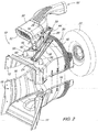
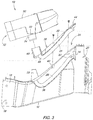
- the Fig. 1 to 3 show a fan cowl 10 having a suction device integrated therein.
- the Fan cover 10 comprises an upper portion 12 and a lower portion 14 and is preferably formed of thermoplastic or duoplastic material with a corresponding manufacturing method, in particular a compression molding process.
- the upper portion 12 and the lower portion 14 are configured to matingly mate with each other on mating flanges 16 to form a channel (or passage or passage) between a fan and a fan To form a cooling module or a radiator of a vehicle.
- a first end 18 of the fan shroud 10 is formed to be disposed in the vicinity of a radiator not shown in the figures, whereas a second end 20 of the fan shroud 10 is formed to be disposed in the vicinity of the fan 22.
- air is drawn from the fan 22 through the radiator.
- the Fig. 2 and 3 it can be seen that the upper portion 12 of the fan cowl 10 has an air channel 24.
- the air channel 24 has a molded in the upper portion 12 of the fan cover 10 molded channel portion 26.
- the air channel 24 further includes a channel portion 28 formed in a channel cover 30.
- the channel cover 30 may be mounted in a complementary manner to the top portion 12 of the fan cowling 10.
- the channel sections 26 and 28 each have a substantially semicircular cross-section, so that the air passage 24 or the air passage in the mounted state of the channel cover 30 at the upper portion 12 of the fan cowl 10 has a substantially circular cross-section.
- a first end 32 of the channel portion 26 terminates at an aperture 34 which is disposed at the second end 20 of the fan cowl 10.
- the aperture 34 is disposed in the vicinity of the fan 22.
- a second end 36 of the channel portion 26 is formed bent upward and terminates substantially in the middle or in the front third between the first end 18 and the second end 20 of the fan cowl 10.
- the channel cover 30 comprises two flanges 38, which on both sides of Channel portion 28 are arranged to fasten the channel cover 30 to the surfaces 40 complementary to the flanges 38, which are formed on both sides of the channel portion 26 to attach.
- Fastening tabs 42 are provided in both the flanges 38 of the channel cover 30 and in the surfaces 40 to secure the channel cover 30 to the fan cowl 10 with appropriate fasteners.
- a first end 44 of the channel portion 28 terminates at one end of the channel cover 30, whereby in the assembled state of the channel cover 30, the circular aperture 34 is completed by the fan cowling 10.
- a mouthpiece or nozzle 46 is provided at the top of the channel cover 30. The nozzle 46 communicates with the second end 48 of the channel portion 28 in a region in which the channel portion 26 of the upper portion 12 of the fan shroud 10 is formed bent upward. Accordingly, the air channel 24 has a channel with a substantially circular cross-section extending from the aperture 34 near the fan 22 and the top-mounted nozzle 46 of the channel cover 30 when the channel cover 30 is secured in place.
- a pre-cleaner 50 for the intake air for the internal combustion engine comprises an air intake 52, a suction port 54 and an air exhaust 56.
- air is drawn through the intake manifold 52 and dirt particles are removed from the intake air and the intake air is cleaned and the purified air exits through the connected to an air inlet, not shown, of an internal combustion engine, also not shown, air outlet 56 from the pre-cleaning device 50.
- the suction for the pre-cleaning device 50 is provided by the vacuum generated by the fan 22 via the suction port 54, which will be described below.
- Two fastening projections 58 are provided on the upper portion 12 of the fan cowl 10.
- the fastening projections 58 correspond to fastening tabs 60, which are arranged on the housing of the pre-cleaning device 50.
- the pre-cleaning device 50 can be attached to the fan cowling 10 by means of appropriate fastening means.
- the negative pressure required for the pre-cleaning device 50 is caused by an air movement caused by the fan 22, wherein the air movement between the intake port 52 of the pre-cleaning device 50 and the aperture 34 of the fan cowl 10 via the suction port 54 and the Air duct 24 extends. Since the pre-cleaning device 50 is mounted or adapted directly to the air duct 24 of the fan cowl 10, no additional, suitable for negative pressure suction hoses or hose clamps are required, which advantageously less space under the hood of the vehicle is needed.
Landscapes
- Engineering & Computer Science (AREA)
- Chemical & Material Sciences (AREA)
- Combustion & Propulsion (AREA)
- Mechanical Engineering (AREA)
- General Engineering & Computer Science (AREA)
- Structures Of Non-Positive Displacement Pumps (AREA)
- Cleaning In General (AREA)
- Nozzles For Electric Vacuum Cleaners (AREA)
- Jet Pumps And Other Pumps (AREA)
- Cleaning Of Streets, Tracks, Or Beaches (AREA)
Applications Claiming Priority (2)
| Application Number | Priority Date | Filing Date | Title |
|---|---|---|---|
| US675619 | 2003-09-30 | ||
| US10/675,619 US6976825B2 (en) | 2003-09-30 | 2003-09-30 | Integrated aspirator and fan shroud |
Publications (3)
| Publication Number | Publication Date |
|---|---|
| EP1520977A2 EP1520977A2 (de) | 2005-04-06 |
| EP1520977A3 EP1520977A3 (de) | 2011-08-17 |
| EP1520977B1 true EP1520977B1 (de) | 2016-06-29 |
Family
ID=34314004
Family Applications (1)
| Application Number | Title | Priority Date | Filing Date |
|---|---|---|---|
| EP04104763.0A Expired - Lifetime EP1520977B1 (de) | 2003-09-30 | 2004-09-29 | Ansaugvorrichtung für eine Vorreinigungseinrichtung in Verbindung mit einer Ventilatorverkleidung |
Country Status (3)
| Country | Link |
|---|---|
| US (1) | US6976825B2 (pt) |
| EP (1) | EP1520977B1 (pt) |
| BR (2) | BRPI0403667A (pt) |
Families Citing this family (9)
| Publication number | Priority date | Publication date | Assignee | Title |
|---|---|---|---|---|
| US20060081353A1 (en) * | 2004-10-19 | 2006-04-20 | Inniger Steven W | Split access fan shroud |
| US7278504B2 (en) * | 2004-10-25 | 2007-10-09 | Deere & Company | Integrated fan shroud air intake system |
| US20100071978A1 (en) * | 2008-09-22 | 2010-03-25 | Clark Equipment Company | Combustion air cleaner scavenge system |
| US8256551B2 (en) * | 2009-12-30 | 2012-09-04 | Agco Corporation | Agricultural vehicle cooling assembly fan shroud with seals for pass-through cooling and exhaust tubes |
| US9222448B2 (en) * | 2014-02-14 | 2015-12-29 | Cnh Industrial America Llc | Air intake system for a work vehicle with improved fan aspiration |
| DE102019117148B4 (de) * | 2019-06-26 | 2022-09-29 | CASO Holding GmbH | Ansauggehäuse und Vorrichtung umfassend ein Ansauggehäuse zur Absaugung von Wra-sen sowie Verfahren zur Absaugung von Wrasen mittels der Vorrichtung und Verwendung der Vorrichtung zur Absaugung von Wrasen |
| USD1009936S1 (en) * | 2019-08-26 | 2024-01-02 | Velossa Tech Engineering Inc. | Ram-air intake |
| DE102019213195A1 (de) * | 2019-09-02 | 2021-03-04 | Deere & Company | Lüfterhutze für ein Fahrzeugsystem |
| US11719203B2 (en) * | 2020-02-05 | 2023-08-08 | Cnh Industrial America Llc | System and method for cleaning an air intake screen of a work vehicle |
Family Cites Families (6)
| Publication number | Priority date | Publication date | Assignee | Title |
|---|---|---|---|---|
| US2197503A (en) * | 1938-04-30 | 1940-04-16 | Oliver Farm Equipment Co | Air intake for air cleaners |
| JPS58187575A (ja) * | 1982-04-26 | 1983-11-01 | Mazda Motor Corp | エアクリ−ナの外気導入構造 |
| DE3232583A1 (de) * | 1982-09-02 | 1984-03-08 | Daimler-Benz Ag, 7000 Stuttgart | Vorrichtung zur reinigung der ansaugluft einer brennkraftmaschine |
| US5427502A (en) * | 1994-03-28 | 1995-06-27 | Deere & Company | Fan shroud aspirator |
| US5564513A (en) * | 1994-07-12 | 1996-10-15 | Automotive Performance International, Inc. | Air filter housing for automobile internal combustion engine |
| US6588524B2 (en) * | 2001-05-31 | 2003-07-08 | Deere & Company | Vacuum pump aspirator for work vehicle pre-cleaner |
-
2003
- 2003-09-30 US US10/675,619 patent/US6976825B2/en not_active Expired - Fee Related
-
2004
- 2004-08-31 BR BR0403667-0A patent/BRPI0403667A/pt active IP Right Grant
- 2004-08-31 BR BRMU8403639-7U patent/BRMU8403639Y1/pt not_active IP Right Cessation
- 2004-09-29 EP EP04104763.0A patent/EP1520977B1/de not_active Expired - Lifetime
Also Published As
| Publication number | Publication date |
|---|---|
| US6976825B2 (en) | 2005-12-20 |
| BRPI0403667A (pt) | 2005-06-07 |
| BRMU8403639Y1 (pt) | 2014-07-22 |
| US20050069412A1 (en) | 2005-03-31 |
| EP1520977A2 (de) | 2005-04-06 |
| EP1520977A3 (de) | 2011-08-17 |
Similar Documents
| Publication | Publication Date | Title |
|---|---|---|
| EP1096133B1 (de) | Ansaugsystem | |
| DE10348575B4 (de) | Abgasrückführsystem für einen Verbrennungsmotor | |
| EP2501922B1 (de) | Saugrohrabschnitt und sauganlage | |
| DE20013534U1 (de) | Vorrichtung zur Rückführung von Gas an einem Verbrennungsmotor | |
| WO1995006807A1 (de) | Drosseleinrichtung | |
| EP0675268A1 (de) | Lüfteranordnung mit Aspirator | |
| DE19626251A1 (de) | Luftführungsanlage | |
| DE102011110285A1 (de) | Ansaugrohrelement und Verdichteranordnung daraus | |
| EP3095995A1 (de) | Ladeluftkühler | |
| WO2001096729A1 (de) | Luftfiltersystem | |
| EP1520977B1 (de) | Ansaugvorrichtung für eine Vorreinigungseinrichtung in Verbindung mit einer Ventilatorverkleidung | |
| EP0840846A1 (de) | Aggregat und schnappvorrichtung für ein aggregat | |
| DE60009111T2 (de) | Baueinheit von saugrohranlage und zylinderkopfhaube | |
| DE102010021929A1 (de) | Ansaugtrakt für eine Verbrennungskraftmaschine | |
| EP0254816B1 (de) | Kurbelgehäuseentlüftung in Kraftfahrzeugen | |
| EP3236038B1 (de) | Heckenschere | |
| EP1422413B1 (de) | Ansaugsystem | |
| EP0989295A2 (de) | Sauganlage für eine Brennkraftmaschine | |
| DE102017204785A1 (de) | Venturimodul für ein Verdichtergehäuse | |
| EP1283351B1 (de) | Ansaugvorrichtung für eine Brennkraftmaschine | |
| EP0832352B1 (de) | Rohrmodul | |
| DE102017223700A1 (de) | Belüftungssystem für eine Kraftfahrzeugleuchte | |
| EP3786458B1 (de) | Lüfterhutze für ein fahrzeugsystem | |
| DE102014117698B4 (de) | Einsetztyp-Ausdehnungsleitung-Integrierte-Luftfiltervorrichtung und Verbrennungsmotoreinlasssystem hierfür | |
| DE102013224878A1 (de) | Einlasssystem mit entfernt angeordneten Filteranordnungen und Verfahren zum Betrieb eines Einlasssystems |
Legal Events
| Date | Code | Title | Description |
|---|---|---|---|
| PUAI | Public reference made under article 153(3) epc to a published international application that has entered the european phase |
Free format text: ORIGINAL CODE: 0009012 |
|
| AK | Designated contracting states |
Kind code of ref document: A2 Designated state(s): AT BE BG CH CY CZ DE DK EE ES FI FR GB GR HU IE IT LI LU MC NL PL PT RO SE SI SK TR |
|
| AX | Request for extension of the european patent |
Extension state: AL HR LT LV MK |
|
| PUAL | Search report despatched |
Free format text: ORIGINAL CODE: 0009013 |
|
| AK | Designated contracting states |
Kind code of ref document: A3 Designated state(s): AT BE BG CH CY CZ DE DK EE ES FI FR GB GR HU IE IT LI LU MC NL PL PT RO SE SI SK TR |
|
| AX | Request for extension of the european patent |
Extension state: AL HR LT LV MK |
|
| RIC1 | Information provided on ipc code assigned before grant |
Ipc: F02M 35/10 20060101AFI20110714BHEP Ipc: F02M 35/02 20060101ALI20110714BHEP Ipc: F02M 35/16 20060101ALI20110714BHEP Ipc: F02M 35/06 20060101ALI20110714BHEP |
|
| 17P | Request for examination filed |
Effective date: 20120217 |
|
| AKX | Designation fees paid |
Designated state(s): DE FR GB IT |
|
| 17Q | First examination report despatched |
Effective date: 20120809 |
|
| GRAP | Despatch of communication of intention to grant a patent |
Free format text: ORIGINAL CODE: EPIDOSNIGR1 |
|
| INTG | Intention to grant announced |
Effective date: 20160120 |
|
| GRAS | Grant fee paid |
Free format text: ORIGINAL CODE: EPIDOSNIGR3 |
|
| GRAA | (expected) grant |
Free format text: ORIGINAL CODE: 0009210 |
|
| AK | Designated contracting states |
Kind code of ref document: B1 Designated state(s): DE FR GB IT |
|
| REG | Reference to a national code |
Ref country code: GB Ref legal event code: FG4D Free format text: NOT ENGLISH |
|
| REG | Reference to a national code |
Ref country code: DE Ref legal event code: R096 Ref document number: 502004015240 Country of ref document: DE |
|
| PGFP | Annual fee paid to national office [announced via postgrant information from national office to epo] |
Ref country code: DE Payment date: 20160819 Year of fee payment: 13 Ref country code: GB Payment date: 20160927 Year of fee payment: 13 |
|
| PG25 | Lapsed in a contracting state [announced via postgrant information from national office to epo] |
Ref country code: IT Free format text: LAPSE BECAUSE OF FAILURE TO SUBMIT A TRANSLATION OF THE DESCRIPTION OR TO PAY THE FEE WITHIN THE PRESCRIBED TIME-LIMIT Effective date: 20160629 |
|
| REG | Reference to a national code |
Ref country code: DE Ref legal event code: R097 Ref document number: 502004015240 Country of ref document: DE |
|
| PLBE | No opposition filed within time limit |
Free format text: ORIGINAL CODE: 0009261 |
|
| STAA | Information on the status of an ep patent application or granted ep patent |
Free format text: STATUS: NO OPPOSITION FILED WITHIN TIME LIMIT |
|
| 26N | No opposition filed |
Effective date: 20170330 |
|
| REG | Reference to a national code |
Ref country code: FR Ref legal event code: ST Effective date: 20170531 |
|
| PG25 | Lapsed in a contracting state [announced via postgrant information from national office to epo] |
Ref country code: FR Free format text: LAPSE BECAUSE OF NON-PAYMENT OF DUE FEES Effective date: 20160930 |
|
| REG | Reference to a national code |
Ref country code: DE Ref legal event code: R119 Ref document number: 502004015240 Country of ref document: DE |
|
| GBPC | Gb: european patent ceased through non-payment of renewal fee |
Effective date: 20170929 |
|
| PG25 | Lapsed in a contracting state [announced via postgrant information from national office to epo] |
Ref country code: GB Free format text: LAPSE BECAUSE OF NON-PAYMENT OF DUE FEES Effective date: 20170929 Ref country code: DE Free format text: LAPSE BECAUSE OF NON-PAYMENT OF DUE FEES Effective date: 20180404 |