EP1520996A2 - Vérin rotatif actionné par fluide - Google Patents
Vérin rotatif actionné par fluide Download PDFInfo
- Publication number
- EP1520996A2 EP1520996A2 EP04022116A EP04022116A EP1520996A2 EP 1520996 A2 EP1520996 A2 EP 1520996A2 EP 04022116 A EP04022116 A EP 04022116A EP 04022116 A EP04022116 A EP 04022116A EP 1520996 A2 EP1520996 A2 EP 1520996A2
- Authority
- EP
- European Patent Office
- Prior art keywords
- hood
- rotary drive
- drive according
- output shaft
- cover
- Prior art date
- Legal status (The legal status is an assumption and is not a legal conclusion. Google has not performed a legal analysis and makes no representation as to the accuracy of the status listed.)
- Granted
Links
Images





Classifications
-
- F—MECHANICAL ENGINEERING; LIGHTING; HEATING; WEAPONS; BLASTING
- F15—FLUID-PRESSURE ACTUATORS; HYDRAULICS OR PNEUMATICS IN GENERAL
- F15B—SYSTEMS ACTING BY MEANS OF FLUIDS IN GENERAL; FLUID-PRESSURE ACTUATORS, e.g. SERVOMOTORS; DETAILS OF FLUID-PRESSURE SYSTEMS, NOT OTHERWISE PROVIDED FOR
- F15B15/00—Fluid-actuated devices for displacing a member from one position to another; Gearing associated therewith
- F15B15/08—Characterised by the construction of the motor unit
- F15B15/12—Characterised by the construction of the motor unit of the oscillating-vane or curved-cylinder type
-
- F—MECHANICAL ENGINEERING; LIGHTING; HEATING; WEAPONS; BLASTING
- F15—FLUID-PRESSURE ACTUATORS; HYDRAULICS OR PNEUMATICS IN GENERAL
- F15B—SYSTEMS ACTING BY MEANS OF FLUIDS IN GENERAL; FLUID-PRESSURE ACTUATORS, e.g. SERVOMOTORS; DETAILS OF FLUID-PRESSURE SYSTEMS, NOT OTHERWISE PROVIDED FOR
- F15B15/00—Fluid-actuated devices for displacing a member from one position to another; Gearing associated therewith
- F15B15/20—Other details, e.g. assembly with regulating devices
- F15B15/22—Other details, e.g. assembly with regulating devices for accelerating or decelerating the stroke
- F15B15/226—Other details, e.g. assembly with regulating devices for accelerating or decelerating the stroke having elastic elements, e.g. springs, rubber pads
-
- F—MECHANICAL ENGINEERING; LIGHTING; HEATING; WEAPONS; BLASTING
- F15—FLUID-PRESSURE ACTUATORS; HYDRAULICS OR PNEUMATICS IN GENERAL
- F15B—SYSTEMS ACTING BY MEANS OF FLUIDS IN GENERAL; FLUID-PRESSURE ACTUATORS, e.g. SERVOMOTORS; DETAILS OF FLUID-PRESSURE SYSTEMS, NOT OTHERWISE PROVIDED FOR
- F15B15/00—Fluid-actuated devices for displacing a member from one position to another; Gearing associated therewith
- F15B15/20—Other details, e.g. assembly with regulating devices
- F15B15/28—Means for indicating the position, e.g. end of stroke
- F15B15/2807—Position switches, i.e. means for sensing of discrete positions only, e.g. limit switches
-
- B—PERFORMING OPERATIONS; TRANSPORTING
- B60—VEHICLES IN GENERAL
- B60G—VEHICLE SUSPENSION ARRANGEMENTS
- B60G2202/00—Indexing codes relating to the type of spring, damper or actuator
- B60G2202/20—Type of damper
- B60G2202/22—Rotary Damper
Definitions
- the invention relates to a fluid-operated rotary drive, with a housing defining a receiving space in which by fluid application about a rotation axis pivotable Swiveling piston is arranged and that a hood and a Cover attached to the hood opening transversely to the axis of rotation contains, with the hood itself in the direction of the axis of rotation opposite wall sections two aligned with each other Has hood openings, in the area of the Swivel piston is rotatably mounted.
- Rotary actuators of this type which are also known as rotary piston drives or swing-wing drives are referred to in the Usually used to components of a device or a machine to twist with changing directions of rotation.
- a rotary drive can be used to to position the valve member of a rotary valve.
- the housing consists of two disc-shaped housing halves, which put together in a plane perpendicular to the axis of rotation joint are.
- the for pivotal mounting of the oscillating piston Serving output shaft is here in central openings the two housing halves rotatably mounted.
- the two housing halves are parallel to the axis of rotation running Screws clamped together.
- a known from US 6,511,040 B2 rotary drive has a housing composed of two hood elements.
- the hood elements are in a longitudinal axis of rotation Joining joining layer.
- the connected to the swivel piston Output shaft is mounted in housing openings, the pairs of complementary, on the two hood parts formed opening halves are formed.
- the Both hood parts are fastened together by screws.
- the lid two spaced apart in the direction of the axis of rotation bearing sections with two flush cover openings has, and that the cover and the hood across the Axial direction of the axis of rotation are inserted into each other, that the hood openings and the cover openings below Formation of two pairs of apertures in pairs, one above the other, wherein in the aperture pairs each one used in both openings engaging centering is through which the lid and the hood held together become.
- an output shaft whose longitudinal axis coincides with the axis of rotation and with the Swivel piston is rotatably connected, passing over the two Centering mounted rotatably relative to the housing is.
- the output shaft is in particular for the production of rotationally fixed connection inserted through the pivot piston.
- the output shaft can also be the two Pass centering pieces coaxially.
- Outer ring and inner part can relative to each other be rotatable, so that the outer ring to the wear-free Wheellagerung of the inner part contributes.
- the outer ring exists expediently of metal, in particular of steel, during the inner part preferably made of plastic material is.
- the output shaft with at least one Centering is rotatably connected. With a one-piece Centering thus makes this centering the Rotary movement of the output shaft in total with.
- a multipart Embodiment of the aforementioned type is the rotational movement the output shaft transmitted to the inner part, the then depending on the configuration alone or together with the outer ring is twisted.
- a radially projecting Stop arm be provided, which is a Drehwinkelvorgabe vibration belongs to the output shaft.
- This angle of rotation setting device If necessary under a hood-like Cover sitting, which removably attached to the housing is and which is expediently transparent.
- sensors can be attached to the Angular position of the stop arm and thus the current angular position to detect the output shaft.
- the hood is made Plastic material and the lid made of metal.
- Such Design is especially advantageous if the hood in the Lid inserted and from this at least in the field of Cover openings is overlapped outside. In this way takes over the hood cross-part of the lid a support function relative to the inside of the hood acting internal pressure.
- hood and the lid only with the respective opening surrounding annular Overlap sections.
- the lid then in particular dull at the edge opening surrounding the hood opening abut the hood wall.
- hood openings and / or the cover openings are expediently at least partially overlapping Fort among the hood or the lid formed. These extensions can protrude like ears.
- the rotary drive with a one-piece, combined Sealing and stop element equipped, the one frame-like, arranged between the lid and the hood Housing seal, a voltage applied to the rotary piston Sealing element and two projecting into the receiving space Buffer elements in integral design includes. You reach thus with a single component a multiple sealing function and a the final impact of the rotary piston in buffering minimizing the end positions.
- Rotary actuator 1 has a housing 2, on which Fastening means 3 are provided which a releasable attachment on a device to be operated 4 allow.
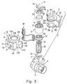
- FIG 5 is exemplified as a device to actuate a rotary valve shown that with respect to the valve body 5 rotatable valve member 6 has, of which in the Drawing only a drive extension is visible.
- Rotary actuator 1 can be attached via its housing 2 on the valve housing 5 be and allows by its operation twisting the valve member 6 in and counterclockwise.
- the housing 2 has inside a receiving space 7, in the a drive element housed in the form of a pivoting piston 8 is.
- the pivoting piston 8 is with respect to a rotation axis 12 pivotable and has one to the axis of rotation 12 coaxial bush-type bearing portion 13, from the radial a wing 14 juts out.
- the lateral surface 15 of the bearing portion 13 is connected to a housing-fixed sealing element 16 in sealing contact.
- Frontal, annular seals 17 of the bearing portion 13 are with the wall of the receiving space 7 in sealing contact. The same applies to a along the edge of the wing 14th extending wing seal 18.
- the standing with the sealing element 16 in sealing contact lateral surface 15 can be seen from one on the outer circumference of the Bearing portion 13 arranged coating may be formed.
- each working chamber 22, 23 opens a housing 2 passing through the fluid channel 21, via a fluidic pressure medium, in particular compressed air, after Need can be supplied or removed.
- a fluidic pressure medium in particular compressed air
- the pivoting movement of the rotary piston 8 can be outside the housing 2 on an output shaft 25 as a reciprocating Tapping rotary motion 26 by a double arrow is indicated.
- This output shaft 25 passes through the Swivel piston 8 in the region of the bearing portion 13, wherein the Longitudinal axis of the output shaft 25 coincides with the axis of rotation 12.
- By the bearing portion 13 with the output shaft 25 is rotatably connected, resulting in a slip-free Torque transmission.
- the bearing section 13 has over a coaxially continuous non-circular profiled piston opening 27, through which the exterior contoured complementarily Output shaft 25 is inserted through, so that in the direction of rotation results in a positive connection.
- a splined profiling intended is for this purpose.
- the output shaft 25 passes axially on both sides of the pivoting piston 8 also the housing wall, wherein the penetration areas as pivot bearing points 28, 29 for the output shaft 25th are formed. In this way, the output shaft 25th rotatably supported with respect to the housing 2.
- coupling means 32 allow a rotationally fixed connection with the component to be twisted, in the present case, the valve member 6.
- the coupling means 32nd exist in the embodiment of a the output shaft 25 coaxially penetrating, non-circular profiled channel. This can be rotationally fixed to the drive extension of the valve member 6 are plugged.
- the housing 2 is made in two parts. It has one Hood 33 and one at the hood opening 35 to the hood 33rd attached lid 34.
- the hood opening 35 is rectangular oriented to the rotation axis 12, so that the hood 33 and the Cover 34 juxtaposed transverse to the axial direction of the axis of rotation 12 are, wherein the lid 34 closes the hood opening 35.
- Hood 33 and cover 34 limit this together the receiving space 7 for the rotary piston. 8
- FIG. 5 it has the hood 33 over two opposite in the direction of the axis of rotation first and second wall portions 36a, 36b, the by a peripheral third wall section 37 with each other are connected.
- the peripheral wall section has a circular arc Course according to the direction of the pivoting movement 24 of the rotary piston 8.
- the center of curvature of the peripheral third wall portion 37 is located on the axis of rotation 12th
- the three wall sections 36a, 36b, 37 define one circular segment-like hood section with an angular extent, in the embodiment, approximately in the range of 130 °.
- the first and second wall sections 36a, 36b extend each in a plane perpendicular to the axis of rotation 12 level. Of the Distance between the two wall sections 36a, 36b corresponds to the height the swinging piston 8, so that this under warranty above-described sealing contact over the inner surface of Sliding wall sections away.
- the first and second wall sections 36a, 36b are each with an opening provided as the first and second hood opening 42a, 42b is called. These hood openings 42a, 42b are aligned with each other, wherein their centers are located on the axis of rotation 12. Part of her Cross-section is located in the extension 38a, 38b of the associated Wall section 36a, 36b. They are each circular designed.
- the lid 34 is two with each other aligned cover openings 43a, 43b provided whose Centers are also on the axis of rotation 12.
- These cover openings 43a, 43b are at two in the direction of the axis of rotation 12 mutually spaced wall portions of the lid 34 provided as first and second bearing portions 44a, 44b be designated because they are at the pivot bearing of the output shaft 25 are involved.
- the bearing portions 44a, 44b each extend at right angles to the axis of rotation 12, wherein their distance from each other the distance measured outside the two first and second wall portions 36a, 36b of Hood 33 corresponds.
- the lid 34 has on the hood 33 side facing about a depression 45. Their depth is chosen so that between the two cover openings 43a, 43b a free Passage is guaranteed.
- the lid 34 thus has a detached from the hood 33 peripheral wall portion 46 at the two bearing portions 44a, 44b are integrally formed and which also defines the recess 45.
- the two bearing sections 44a, 44b are partially projecting towards the hood 33 ear-like projections 47a, 47b of the respective bearing section 44a, 44b are formed and have a circular Cross-section.
- the peripheral wall portion 46 terminates laterally with two wings projecting wall sections 48, which are very flat. In the center of the peripheral wall portion 46 is one of the hood 33 protruding connecting extension 52 integrally formed, in the two fluid channels 21 are formed.
- the hood 33 and the lid 34 transversely to the axial direction of the axis of rotation 12 into one another plugged that the hood openings 42a, 42b and the lid openings 43a, 43b to form two Aperture pairs 53, 54 in pairs aligned in the axial direction the axis of rotation 12 are above one another.
- the hood 33 is inserted in the lid 34 and is from this in the region of its cover openings 43a, 43b overlapped on the outside like a clip.
- hood 33 and the Cover 34 Due to the special shape of the hood 33 and the Cover 34 results in the embodiment that is the hood 33 and the lid 34 in the nested condition only with the respective opening 42a, 42b; 43a, 43b overlap surrounding annular sections. In order to connected is a relatively low material requirement for the Chassis components.
- the hood 33 overlaps and the lid 34 only in the peripheral region of the aforementioned Perforations.
- the two components without mutual intervention set flat against each other.
- the two wing-like wall sections 48 at the both sides of the extensions 38 a, 38 b provided, the Hood opening 35 bounding edge surfaces 55 of the hood wall at.
- hood 33 and cover 34 The mated state of hood 33 and cover 34 is secured by two centering pieces 56, 57, of which one each in one of the aperture pairs 53, 54 is inserted.
- the axial dimensions of the centering pieces 56, 57 are here dimensioned such that they in each case in both openings 42a, 43a; 42B, 43B of a respective aperture pair 43, 54 intervention.
- hood 33 and cover 34 are transverse to Rotary axis 12 immovably connected. simultaneously These two components are in the peripheral region of the hood opening 35 together.
- the centering pieces 56, 57 are sufficient therefore, to the hood 33 and the lid 34 firmly together connect to. Additional fasteners, for example Screws are not required.
- the assembly designed therefore extremely simple.
- the two aperture pairs 33, 54 each define one the above-mentioned two pivot points 28, 29 for the output shaft 25.
- the output shaft 25 via the two centering pieces 56, 57 is rotatably mounted on the housing 2.
- the two centering pieces 56, 57 are annular and each have an axial opening 58, in which the Output shaft 25 with axially on both sides of the rotary piston. 8 engages lying longitudinal sections. Preferred are the Openings 58 profiled so that a rotationally fixed connection between the respective centering piece 56, 57 and the is present through this through-going output shaft 25.
- the centering pieces 56, 57 respectively formed in two parts. You own one in particular made of metal, for example steel, existing outer ring 59, the outer diameter of the inner diameter of the openings 42a, 42b, 43a, 43b corresponds. This is decisive for the mutual centering of hood 33 and cover 34th as well as for the cohesion between these two components responsible. He is preferably designed sleeve-like and formed relatively thin-walled.
- a second part of the centering pieces 56, 57.ist is an annular Inner part 60 is provided, which concentrically in the outer ring 59 is inserted. In this case, a relative rotatability exist between the outer ring 59 and the inner part 60.
- the inner part 60 has the opening 58, so that it is motion-coupled with the output shaft 25 in the direction of rotation is.
- the inner part 60 is made of plastic material.
- both the hood 33rd as well as the lid 34 of easy-to-molding plastic material manufacture. Since the working chambers 22, 23 in operation the rotary drive 1 but are subjected to internal pressure, there is a problem of ensuring sufficient Strength. In the embodiment, therefore, there is the Lid 34 made of metal, such as aluminum or from Steel, so that it partially overlaps the outside of the hood 33, acts as a support for the hood wall, the thus can withstand a high internal pressure.
- the securing elements 65 formed by resilient snap rings, which are plugged onto the output shaft 25.
- the security elements 65 axially flank the centering 56, 57 and hold them in place axially.
- the joining area between the hood 33 and the lid 34 is sealed by a cord-like housing seal 66, the the longitudinal course of the hood opening 35 limiting edge region the hood wall follows.
- the housing seal 66 is located in particular on the edge surface 55.
- the housing seal 66 a in Figure 2 have schematically indicated sealing lip 67, on the inner surface of the formed in the hood 33 section the receiving space 7 sealingly comes to rest.
- the housing seal 66 is part a one-piece combined shown separately in Figure 4 Sealing and stop element 68.
- the housing seal 66 is a frame-shaped. In one middle area extends between two spaced ones Strand sections 69 of the housing seal 66 in one piece trained with these, above already mentioned sealing element 16.
- a buffer element 73 is integrally formed, which in the installed state of the sealing and stop element 68th each end face in the circular segment-like section 64th the receiving space 7 in and thus the wing 14 of the Swinging piston 8 protrudes.
- the respective buffer element 73 may be on the back of the Support wing-like wall portion 48 of the lid 34.
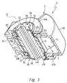
- this Trap is located in the axial extension of the housing. 2 outside this one with respect to the axis of rotation 12 radially projecting Stop arm 75, which rotatably coupled to the output shaft is. It may be at the stop arm 75 to a separate Act on the component in the following axially Centering rotatably attached to the output shaft 25 becomes.
- the stop arm 75 fixed and in particular integral with the rotationally fixed to the output shaft 25 connected component of one of the centering 56 connected is.
- the stop arm 75 integrally connected to one of the internal parts 60.
- the Drehwinkelvorgabe worn 74 has two in the pivoting path the stop arm 75 arranged stop elements 76, the the end portion 77 of the stop arm 75 protrude.
- the stop arm 75 makes the Rotary movement of the output shaft 25 with and is comparable the pivoting piston 8 is pivoted about the axis of rotation 12, wherein the pivoting movement indicated by a double arrow at 78 is.
- the stop arm 75 is integral with a centering piece 56 is executed, it preferably consists of Plastic material. Nevertheless, the required wear resistance in cooperation with the stop elements 76th to ensure are in the end portion 77 of the stop arm 75 made of steel or other wear-resistant Metal, preferably ball-like impact elements 79 used, which work together with the stop elements 76.
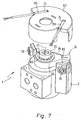
- the Drehwinkelvorgabe coupled 74 enclosing hood-like cover 83 the components of the rotational angle setting device 74 before Pollution protected and will be personal injury prevented.
- the cover 83 is suitably made of a transparent Plastic material, so that from the outside at any time convenient function monitoring is possible.
- angle of rotation setting device 74 is equipped with funds that the detection at least one rotational angle position of the output shaft 25th allow and which are particularly suitable to the two To detect end positions of the output shaft 25.
Landscapes
- Engineering & Computer Science (AREA)
- Physics & Mathematics (AREA)
- Fluid Mechanics (AREA)
- Mechanical Engineering (AREA)
- General Engineering & Computer Science (AREA)
- Actuator (AREA)
- Hydraulic Motors (AREA)
- Multiple-Way Valves (AREA)
- Applications Or Details Of Rotary Compressors (AREA)
Applications Claiming Priority (2)
| Application Number | Priority Date | Filing Date | Title |
|---|---|---|---|
| DE10346091 | 2003-10-04 | ||
| DE10346091A DE10346091B3 (de) | 2003-10-04 | 2003-10-04 | Fluidbetätigter Drehantrieb |
Publications (3)
| Publication Number | Publication Date |
|---|---|
| EP1520996A2 true EP1520996A2 (fr) | 2005-04-06 |
| EP1520996A3 EP1520996A3 (fr) | 2005-07-27 |
| EP1520996B1 EP1520996B1 (fr) | 2007-04-18 |
Family
ID=33483132
Family Applications (1)
| Application Number | Title | Priority Date | Filing Date |
|---|---|---|---|
| EP04022116A Expired - Lifetime EP1520996B1 (fr) | 2003-10-04 | 2004-09-17 | Vérin rotatif actionné par fluide |
Country Status (4)
| Country | Link |
|---|---|
| EP (1) | EP1520996B1 (fr) |
| CN (1) | CN100404883C (fr) |
| AT (1) | ATE360150T1 (fr) |
| DE (2) | DE10346091B3 (fr) |
Cited By (2)
| Publication number | Priority date | Publication date | Assignee | Title |
|---|---|---|---|---|
| WO2008110228A1 (fr) | 2007-03-15 | 2008-09-18 | Festo Ag & Co. Kg | Capot de protection et dispositif d'entraînement équipé de ce capot |
| CN103711741A (zh) * | 2013-12-17 | 2014-04-09 | 东南大学 | 一种带扭矩和角度反馈的机器人关节旋转液压缸 |
Families Citing this family (6)
| Publication number | Priority date | Publication date | Assignee | Title |
|---|---|---|---|---|
| MX2010009437A (es) * | 2008-02-29 | 2011-03-03 | Cbe Global Holdings Inc | Sistema de transmision de eje-simple y metodo. |
| DE102009011764A1 (de) | 2009-03-04 | 2010-09-09 | Festo Ag & Co. Kg | Drehantriebsvorrichtung |
| US9399916B2 (en) * | 2011-09-28 | 2016-07-26 | Festo Ag & Co. Kg | Fluid-actuated rotary drive device |
| CN108457925B (zh) * | 2018-01-31 | 2020-03-03 | 北京航天发射技术研究所 | 一种气动式旋转锁紧装置 |
| DE102018205636B4 (de) * | 2018-04-13 | 2020-01-16 | Festo Ag & Co. Kg | Aktoranordnung |
| CN111577395A (zh) * | 2020-04-29 | 2020-08-25 | 韩丁 | 气动发动机 |
Family Cites Families (6)
| Publication number | Priority date | Publication date | Assignee | Title |
|---|---|---|---|---|
| ES303407A1 (es) * | 1963-08-26 | 1965-02-01 | Fabbrica Italiana Magneti Marelli S P A | Motor de piston giratorio, a presion de fluido, para accionar con movimiento alternativo organos en general. |
| EP0136492B1 (fr) * | 1983-08-31 | 1987-03-04 | Festo KG | Moteur à piston oscillant |
| DE3941255C2 (de) * | 1989-12-14 | 1994-02-03 | Festo Kg | Fluidbetätigter Schwenkkolbenmotor |
| CN2132013Y (zh) * | 1992-06-23 | 1993-05-05 | 上海市水产研究所 | 一种摆动缸 |
| US6511040B2 (en) * | 1997-10-07 | 2003-01-28 | Murray J. Gardner | Pneumatic actuator |
| CN2321966Y (zh) * | 1998-02-24 | 1999-06-02 | 宁波东海液压件实业有限公司 | 双制动液压摆线马达 |
-
2003
- 2003-10-04 DE DE10346091A patent/DE10346091B3/de not_active Expired - Fee Related
-
2004
- 2004-09-17 AT AT04022116T patent/ATE360150T1/de not_active IP Right Cessation
- 2004-09-17 EP EP04022116A patent/EP1520996B1/fr not_active Expired - Lifetime
- 2004-09-17 DE DE502004003526T patent/DE502004003526D1/de not_active Expired - Lifetime
- 2004-10-08 CN CNB2004100835746A patent/CN100404883C/zh not_active Expired - Fee Related
Cited By (3)
| Publication number | Priority date | Publication date | Assignee | Title |
|---|---|---|---|---|
| WO2008110228A1 (fr) | 2007-03-15 | 2008-09-18 | Festo Ag & Co. Kg | Capot de protection et dispositif d'entraînement équipé de ce capot |
| CN103711741A (zh) * | 2013-12-17 | 2014-04-09 | 东南大学 | 一种带扭矩和角度反馈的机器人关节旋转液压缸 |
| CN103711741B (zh) * | 2013-12-17 | 2015-10-28 | 东南大学 | 一种带扭矩和角度反馈的机器人关节旋转液压缸 |
Also Published As
| Publication number | Publication date |
|---|---|
| EP1520996A3 (fr) | 2005-07-27 |
| ATE360150T1 (de) | 2007-05-15 |
| EP1520996B1 (fr) | 2007-04-18 |
| DE10346091B3 (de) | 2004-12-30 |
| DE502004003526D1 (de) | 2007-05-31 |
| CN1603636A (zh) | 2005-04-06 |
| CN100404883C (zh) | 2008-07-23 |
Similar Documents
| Publication | Publication Date | Title |
|---|---|---|
| DE19950582B9 (de) | Betätigungsvorrichtung für ein drehbares Verschlussteil eines Ventils | |
| DE102007030006B4 (de) | Vakuumventil | |
| DE4139178C2 (de) | Drehflügelstoßdämpfer | |
| EP1433954B1 (fr) | Machine à pistons axiaux | |
| DE69928742T2 (de) | Geräuschloser Dämpfer mit Antiklapperwelle | |
| EP0604608B1 (fr) | Robinet d'arret | |
| EP2614260B1 (fr) | Dispositif d'entraînement rotatif actionné par un fluide | |
| EP1520996B1 (fr) | Vérin rotatif actionné par fluide | |
| DE2605857A1 (de) | Tuerschliesser | |
| DE2445377A1 (de) | Vorrichtung zum einstellen der daempfkraft eines stossdaempfers | |
| EP0622574B1 (fr) | Dispositif de commande d'une pièce rotative d'obturation d'une soupape | |
| DE3629569C1 (de) | Sanitaeres Ventil | |
| DE4426471A1 (de) | Drehabsperrorgan | |
| EP1899611B1 (fr) | Piston pour un vérin | |
| DE3437608A1 (de) | Schwenkkolbenmotor | |
| EP0136492B1 (fr) | Moteur à piston oscillant | |
| EP2093451B1 (fr) | Agencement de transmission de force de freinage | |
| DE10145200A1 (de) | Ventil | |
| DE3821351C2 (fr) | ||
| DE60009271T2 (de) | Gaszylinder | |
| DE102019204446A1 (de) | Fluidbetätigte Drehantriebsvorrichtung | |
| DE3002626C2 (de) | Dichtungsvorrichtung zum Abdichten zweier Räume unterschiedlichen Druckes | |
| DE4119402C2 (de) | Schieberventil | |
| EP0561294B1 (fr) | Soupape à force équilibrée | |
| DE3337422C2 (de) | Hydraulischer oder pneumatischer Schwenkkolbenmotor |
Legal Events
| Date | Code | Title | Description |
|---|---|---|---|
| PUAI | Public reference made under article 153(3) epc to a published international application that has entered the european phase |
Free format text: ORIGINAL CODE: 0009012 |
|
| AK | Designated contracting states |
Kind code of ref document: A2 Designated state(s): AT BE BG CH CY CZ DE DK EE ES FI FR GB GR HU IE IT LI LU MC NL PL PT RO SE SI SK TR |
|
| AX | Request for extension of the european patent |
Extension state: AL HR LT LV MK |
|
| PUAL | Search report despatched |
Free format text: ORIGINAL CODE: 0009013 |
|
| AK | Designated contracting states |
Kind code of ref document: A3 Designated state(s): AT BE BG CH CY CZ DE DK EE ES FI FR GB GR HU IE IT LI LU MC NL PL PT RO SE SI SK TR |
|
| AX | Request for extension of the european patent |
Extension state: AL HR LT LV MK |
|
| RIC1 | Information provided on ipc code assigned before grant |
Ipc: 7F 15B 15/22 B Ipc: 7F 03C 4/00 B Ipc: 7F 15B 15/12 A Ipc: 7F 15B 15/24 B Ipc: 7F 15B 15/28 B |
|
| 17P | Request for examination filed |
Effective date: 20051110 |
|
| AKX | Designation fees paid |
Designated state(s): AT BE BG CH CY CZ DE DK EE ES FI FR GB GR HU IE IT LI LU MC NL PL PT RO SE SI SK TR |
|
| GRAP | Despatch of communication of intention to grant a patent |
Free format text: ORIGINAL CODE: EPIDOSNIGR1 |
|
| GRAS | Grant fee paid |
Free format text: ORIGINAL CODE: EPIDOSNIGR3 |
|
| GRAA | (expected) grant |
Free format text: ORIGINAL CODE: 0009210 |
|
| AK | Designated contracting states |
Kind code of ref document: B1 Designated state(s): AT BE BG CH CY CZ DE DK EE ES FI FR GB GR HU IE IT LI LU MC NL PL PT RO SE SI SK TR |
|
| PG25 | Lapsed in a contracting state [announced via postgrant information from national office to epo] |
Ref country code: FI Free format text: LAPSE BECAUSE OF FAILURE TO SUBMIT A TRANSLATION OF THE DESCRIPTION OR TO PAY THE FEE WITHIN THE PRESCRIBED TIME-LIMIT Effective date: 20070418 Ref country code: SI Free format text: LAPSE BECAUSE OF FAILURE TO SUBMIT A TRANSLATION OF THE DESCRIPTION OR TO PAY THE FEE WITHIN THE PRESCRIBED TIME-LIMIT Effective date: 20070418 |
|
| GBT | Gb: translation of ep patent filed (gb section 77(6)(a)/1977) |
Effective date: 20070418 |
|
| REG | Reference to a national code |
Ref country code: CH Ref legal event code: EP |
|
| REG | Reference to a national code |
Ref country code: IE Ref legal event code: FG4D Free format text: LANGUAGE OF EP DOCUMENT: GERMAN |
|
| REF | Corresponds to: |
Ref document number: 502004003526 Country of ref document: DE Date of ref document: 20070531 Kind code of ref document: P |
|
| PG25 | Lapsed in a contracting state [announced via postgrant information from national office to epo] |
Ref country code: SE Free format text: LAPSE BECAUSE OF FAILURE TO SUBMIT A TRANSLATION OF THE DESCRIPTION OR TO PAY THE FEE WITHIN THE PRESCRIBED TIME-LIMIT Effective date: 20070718 |
|
| PG25 | Lapsed in a contracting state [announced via postgrant information from national office to epo] |
Ref country code: ES Free format text: LAPSE BECAUSE OF FAILURE TO SUBMIT A TRANSLATION OF THE DESCRIPTION OR TO PAY THE FEE WITHIN THE PRESCRIBED TIME-LIMIT Effective date: 20070729 |
|
| ET | Fr: translation filed | ||
| PG25 | Lapsed in a contracting state [announced via postgrant information from national office to epo] |
Ref country code: PT Free format text: LAPSE BECAUSE OF FAILURE TO SUBMIT A TRANSLATION OF THE DESCRIPTION OR TO PAY THE FEE WITHIN THE PRESCRIBED TIME-LIMIT Effective date: 20070918 |
|
| PG25 | Lapsed in a contracting state [announced via postgrant information from national office to epo] |
Ref country code: PL Free format text: LAPSE BECAUSE OF FAILURE TO SUBMIT A TRANSLATION OF THE DESCRIPTION OR TO PAY THE FEE WITHIN THE PRESCRIBED TIME-LIMIT Effective date: 20070418 |
|
| REG | Reference to a national code |
Ref country code: IE Ref legal event code: FD4D |
|
| PG25 | Lapsed in a contracting state [announced via postgrant information from national office to epo] |
Ref country code: IE Free format text: LAPSE BECAUSE OF FAILURE TO SUBMIT A TRANSLATION OF THE DESCRIPTION OR TO PAY THE FEE WITHIN THE PRESCRIBED TIME-LIMIT Effective date: 20070418 Ref country code: CZ Free format text: LAPSE BECAUSE OF FAILURE TO SUBMIT A TRANSLATION OF THE DESCRIPTION OR TO PAY THE FEE WITHIN THE PRESCRIBED TIME-LIMIT Effective date: 20070418 Ref country code: BG Free format text: LAPSE BECAUSE OF FAILURE TO SUBMIT A TRANSLATION OF THE DESCRIPTION OR TO PAY THE FEE WITHIN THE PRESCRIBED TIME-LIMIT Effective date: 20070718 Ref country code: DK Free format text: LAPSE BECAUSE OF FAILURE TO SUBMIT A TRANSLATION OF THE DESCRIPTION OR TO PAY THE FEE WITHIN THE PRESCRIBED TIME-LIMIT Effective date: 20070418 |
|
| PLBE | No opposition filed within time limit |
Free format text: ORIGINAL CODE: 0009261 |
|
| STAA | Information on the status of an ep patent application or granted ep patent |
Free format text: STATUS: NO OPPOSITION FILED WITHIN TIME LIMIT |
|
| PG25 | Lapsed in a contracting state [announced via postgrant information from national office to epo] |
Ref country code: SK Free format text: LAPSE BECAUSE OF FAILURE TO SUBMIT A TRANSLATION OF THE DESCRIPTION OR TO PAY THE FEE WITHIN THE PRESCRIBED TIME-LIMIT Effective date: 20070418 |
|
| 26N | No opposition filed |
Effective date: 20080121 |
|
| BERE | Be: lapsed |
Owner name: FESTO A.G. & CO. Effective date: 20070930 |
|
| PG25 | Lapsed in a contracting state [announced via postgrant information from national office to epo] |
Ref country code: MC Free format text: LAPSE BECAUSE OF NON-PAYMENT OF DUE FEES Effective date: 20070930 Ref country code: GR Free format text: LAPSE BECAUSE OF FAILURE TO SUBMIT A TRANSLATION OF THE DESCRIPTION OR TO PAY THE FEE WITHIN THE PRESCRIBED TIME-LIMIT Effective date: 20070719 |
|
| PG25 | Lapsed in a contracting state [announced via postgrant information from national office to epo] |
Ref country code: RO Free format text: LAPSE BECAUSE OF FAILURE TO SUBMIT A TRANSLATION OF THE DESCRIPTION OR TO PAY THE FEE WITHIN THE PRESCRIBED TIME-LIMIT Effective date: 20070418 |
|
| PG25 | Lapsed in a contracting state [announced via postgrant information from national office to epo] |
Ref country code: BE Free format text: LAPSE BECAUSE OF NON-PAYMENT OF DUE FEES Effective date: 20070930 |
|
| PG25 | Lapsed in a contracting state [announced via postgrant information from national office to epo] |
Ref country code: AT Free format text: LAPSE BECAUSE OF NON-PAYMENT OF DUE FEES Effective date: 20070917 |
|
| PGFP | Annual fee paid to national office [announced via postgrant information from national office to epo] |
Ref country code: NL Payment date: 20080915 Year of fee payment: 5 |
|
| PG25 | Lapsed in a contracting state [announced via postgrant information from national office to epo] |
Ref country code: EE Free format text: LAPSE BECAUSE OF FAILURE TO SUBMIT A TRANSLATION OF THE DESCRIPTION OR TO PAY THE FEE WITHIN THE PRESCRIBED TIME-LIMIT Effective date: 20070418 |
|
| REG | Reference to a national code |
Ref country code: CH Ref legal event code: PL |
|
| PG25 | Lapsed in a contracting state [announced via postgrant information from national office to epo] |
Ref country code: LI Free format text: LAPSE BECAUSE OF NON-PAYMENT OF DUE FEES Effective date: 20070930 Ref country code: CH Free format text: LAPSE BECAUSE OF NON-PAYMENT OF DUE FEES Effective date: 20070930 |
|
| PG25 | Lapsed in a contracting state [announced via postgrant information from national office to epo] |
Ref country code: CY Free format text: LAPSE BECAUSE OF FAILURE TO SUBMIT A TRANSLATION OF THE DESCRIPTION OR TO PAY THE FEE WITHIN THE PRESCRIBED TIME-LIMIT Effective date: 20070418 |
|
| PG25 | Lapsed in a contracting state [announced via postgrant information from national office to epo] |
Ref country code: LU Free format text: LAPSE BECAUSE OF NON-PAYMENT OF DUE FEES Effective date: 20070917 |
|
| PG25 | Lapsed in a contracting state [announced via postgrant information from national office to epo] |
Ref country code: TR Free format text: LAPSE BECAUSE OF FAILURE TO SUBMIT A TRANSLATION OF THE DESCRIPTION OR TO PAY THE FEE WITHIN THE PRESCRIBED TIME-LIMIT Effective date: 20070418 Ref country code: HU Free format text: LAPSE BECAUSE OF FAILURE TO SUBMIT A TRANSLATION OF THE DESCRIPTION OR TO PAY THE FEE WITHIN THE PRESCRIBED TIME-LIMIT Effective date: 20071019 |
|
| PG25 | Lapsed in a contracting state [announced via postgrant information from national office to epo] |
Ref country code: CH Free format text: LAPSE BECAUSE OF NON-PAYMENT OF DUE FEES Effective date: 20080930 Ref country code: LI Free format text: LAPSE BECAUSE OF NON-PAYMENT OF DUE FEES Effective date: 20080930 |
|
| REG | Reference to a national code |
Ref country code: NL Ref legal event code: V1 Effective date: 20100401 |
|
| PG25 | Lapsed in a contracting state [announced via postgrant information from national office to epo] |
Ref country code: NL Free format text: LAPSE BECAUSE OF NON-PAYMENT OF DUE FEES Effective date: 20100401 |
|
| PGFP | Annual fee paid to national office [announced via postgrant information from national office to epo] |
Ref country code: GB Payment date: 20120823 Year of fee payment: 9 |
|
| PGFP | Annual fee paid to national office [announced via postgrant information from national office to epo] |
Ref country code: DE Payment date: 20120725 Year of fee payment: 9 Ref country code: IT Payment date: 20120912 Year of fee payment: 9 |
|
| PGFP | Annual fee paid to national office [announced via postgrant information from national office to epo] |
Ref country code: FR Payment date: 20121008 Year of fee payment: 9 |
|
| GBPC | Gb: european patent ceased through non-payment of renewal fee |
Effective date: 20130917 |
|
| REG | Reference to a national code |
Ref country code: DE Ref legal event code: R119 Ref document number: 502004003526 Country of ref document: DE Effective date: 20140401 |
|
| REG | Reference to a national code |
Ref country code: FR Ref legal event code: ST Effective date: 20140530 |
|
| PG25 | Lapsed in a contracting state [announced via postgrant information from national office to epo] |
Ref country code: GB Free format text: LAPSE BECAUSE OF NON-PAYMENT OF DUE FEES Effective date: 20130917 |
|
| PG25 | Lapsed in a contracting state [announced via postgrant information from national office to epo] |
Ref country code: FR Free format text: LAPSE BECAUSE OF NON-PAYMENT OF DUE FEES Effective date: 20130930 Ref country code: IT Free format text: LAPSE BECAUSE OF NON-PAYMENT OF DUE FEES Effective date: 20130917 Ref country code: DE Free format text: LAPSE BECAUSE OF NON-PAYMENT OF DUE FEES Effective date: 20140401 |