EP1521023B1 - Spindellagerung in einem Fluidleitungsschieber - Google Patents
Spindellagerung in einem Fluidleitungsschieber Download PDFInfo
- Publication number
- EP1521023B1 EP1521023B1 EP04016116A EP04016116A EP1521023B1 EP 1521023 B1 EP1521023 B1 EP 1521023B1 EP 04016116 A EP04016116 A EP 04016116A EP 04016116 A EP04016116 A EP 04016116A EP 1521023 B1 EP1521023 B1 EP 1521023B1
- Authority
- EP
- European Patent Office
- Prior art keywords
- bearing
- bushing
- sluice valve
- spindle
- fluid conduit
- Prior art date
- Legal status (The legal status is an assumption and is not a legal conclusion. Google has not performed a legal analysis and makes no representation as to the accuracy of the status listed.)
- Expired - Lifetime
Links
Images
Classifications
-
- F—MECHANICAL ENGINEERING; LIGHTING; HEATING; WEAPONS; BLASTING
- F16—ENGINEERING ELEMENTS AND UNITS; GENERAL MEASURES FOR PRODUCING AND MAINTAINING EFFECTIVE FUNCTIONING OF MACHINES OR INSTALLATIONS; THERMAL INSULATION IN GENERAL
- F16K—VALVES; TAPS; COCKS; ACTUATING-FLOATS; DEVICES FOR VENTING OR AERATING
- F16K31/00—Actuating devices; Operating means; Releasing devices
- F16K31/44—Mechanical actuating means
- F16K31/50—Mechanical actuating means with screw-spindle or internally threaded actuating means
- F16K31/508—Mechanical actuating means with screw-spindle or internally threaded actuating means the actuating element being rotatable, non-rising, and driving a non-rotatable axially-sliding element
Definitions
- the invention relates to a fluid line slider spindle bearing.
- Such slides serve to limit or interrupt the fluid flow (gaseous or liquid medium) in a conduit, for example a gas or water supply conduit.
- the slides include a slidable by a spindle shut-off member, with which the passage of the flowing medium can be closed or opened through the conduit.
- such slides include a slider top which receives a bushing which can rotatably support a bearing portion of a spindle.
- the common spindle bearings are designed so that usually a metallic holding part made of corrosion-resistant material, e.g. Bronze or brass is screwed into an internal thread on the slide upper part. This brass part then holds the spindle and removes O-rings, for sealing against the spindle and against the shell casing.
- a metallic holding part made of corrosion-resistant material, e.g. Bronze or brass
- spindle bearings require a high demand for material processing. Both the upper part of the slide and the bushing (brass holding part) must be threaded and machined on their sliding surfaces so that the spindle is easily turned. Also arise in these operations bare metal surfaces that are susceptible to corrosion.
- the advantages of the present invention are based on that at least the sliding surfaces of the bearing bush comprise a lubricious plastic material. Through this choice of material, the processing cost is eliminated or optimally minimized. Furthermore, such a material ensures that corrosion attack surfaces are no longer available. In particular, the fluid line spool bearing can thereby be made much more cost-effective.
- the bearing bush is made entirely of the lubricious plastic material.
- bearing bush or the spindle receptacles for sealing elements serve e.g. for sealing on the spindle or on the slide upper part and they are in particular annular grooves for receiving O-ring seals.
- the fluid line slider spindle bearing according to the invention can be designed so that the bearing bush has a bush bottom and a bush upper part, wherein the sealing elements are arranged in particular on the bush bottom part. It is possible to store the bush upper part in the bush bottom, in particular in a cup-like recess. The bearing surface between slide upper part and bearing bush can therefore only be formed by the bush bottom part.
- the bearing bush by means of a hook element, in particular by means of a snap hook, locked in the slide upper part against axial displacement.
- the bearing bush can be locked by means of a round ring made of metal or plastic, in particular by means of a slotted circular ring in the slide upper part against axial displacement.
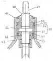
- the slider upper part is provided with the reference numeral 10;
- the spindle bears the reference numeral 20 and the bearing bush carries the reference numeral 30.
- the spindle 20 is rotatably mounted in the interior of the slider top 10, by means of the two-part bearing bush 30 which comprises a bushing part 31 and a bushing upper part 32, which in a cup-like recess of the female lower part 31 is received.
- the spindle 20 has at its upper end a tool engagement 24, and at a distance thereof an annular projection 22.
- the annular projection 22 rests on the bushing part 31 within the cup-like formation, and then comes on the projection 22 - in abutment with the spindle 20 - the bush upper part 32 to lie.
- the bush lower part 31 For sealing against the spindle 20, the bush lower part 31 has inside two grooves, in which the O-rings 42 and 43 are located.
- the bush lower part 31 on the outside In turn has a groove in which an O-ring 41 is arranged. This ensures that the fluid in the interior of the slide upper part can not escape through the spindle bearing.
- the bushing, so the bushing part 31 and the bush upper part 32 are formed of a lubricious plastic material.
- the following materials can be used: POM, PTFE, acetal resins.
- the bush 30 and the spindle 20 can be stored in different ways in the slide upper part 10.
- two types of storage are shown.
- a first type of storage is realized by means of a hook element 50, which has an extension 51, which can engage in a recess in the inner wall of the slide upper part.
- the hook element 50 is firmly seated on the bush upper part 32.
- a further axial displacement safety device is shown in the lower part of the bush bottom part 31, a further axial displacement safety device is shown.
- the ring 53 surrounds the bushing lower part 31 at an obliquely converging surface and is supported outside in the upper slide part in an annular groove. It prevents a downward shift of the bush spindle unit.
Landscapes
- Engineering & Computer Science (AREA)
- General Engineering & Computer Science (AREA)
- Mechanical Engineering (AREA)
- Sliding-Contact Bearings (AREA)
- Magnetic Bearings And Hydrostatic Bearings (AREA)
Description
- Die Erfindung betrifft eine Fluidleitungsschieber-Spindellagerung. Solche Schieber dienen der Begrenzung bzw. Unterbrechung des Fluidstroms (gasförmiges oder flüssiges Medium) in einer Leitung, beispielsweise einer Gas- oder Wasserversorgungsleitung. Die Schieber enthalten ein durch eine Spindel verschiebbares Absperrglied, mit dem der Durchgang des strömenden Mediums durch die Leitung geschlossen oder geöffnet werden kann.
- Herkömmlicherweise umfassen solche Schieber ein Schieberoberteil, das eine Lagerbuchse aufnimmt, welche einen Lagerungsabschnitt einer Spindel drehbar lagern kann. Die gängigen Spindellagerungen sind so ausgeführt, dass in der Regel ein metallisches Halteteil aus korrosionsbeständigem Material, z.B. Bronze oder Messing in ein Innengewinde am Schieberoberteil eingeschraubt wird. Dieses Messingteil hält dann die Spindel und nimmt O-Ringe ab, zur Abdichtung gegen die Spindel und gegen das Oberteilgehäuse. Solche Anordnungen sind aus US 3,753,569 und US 3,064,674 bekannt.
- Nachteiligerweise erfordern solche Spindellagerungen einen hohen Bedarf an Materialbearbeitung. Sowohl das Schieberoberteil als auch die Lagerbuchse (Messinghalteteil) müssen mit einem Gewinde versehen werden und an ihren Gleitflächen so bearbeitet werden, dass die Spindel leicht drehbar ist. Auch entstehen bei diesen Bearbeitungen blanke Metallflächen, die korrosionsanfällig sind.
- Es ist die Aufgabe der vorliegenden Erfindung, eine Spindellagerung vorzuschlagen, welche die oben genannten Nachteile nicht mehr aufweist. Insbesondere soll der Bearbeitungsbedarf an den Spindellagerungsteilen entfallen oder äußerst gering gehalten werden. Unter anderem soll auch verbesserter Korrosionsschutz ermöglicht werden.
- Diese Aufgabe wird erfindungsgemäß durch eine Spindellagerung gemäß dem Anspruch 1 gelöst. Die Unteransprüche definieren vorteilhafte Ausführungsformen der Erfindung.
- Die Vorteile der vorliegenden Erfindung beruhen darauf, dass zumindest die Gleitflächen der Lagerbuchse ein gleitfähiges Kunststoffmaterial umfassen. Durch diese Materialwahl wird der Bearbeitungsaufwand eliminiert bzw. optimal minimiert. Ferner sorgt ein solches Material dafür, dass Korrosions-Angriffsflächen nicht mehr vorhanden sind. Insbesondere kann die Fluidleitungsschieber-Spindellagerung dadurch sehr viel kostengünstiger gestaltet werden.
- Gemäß einer Ausführungsform der Erfindung besteht die Lagerbuchse vollständig aus dem gleitfähigen Kunststoffmaterial.
- Gemäß einer weiteren Ausführungsform weisen die Lagerbuchse oder die Spindel Aufnahmen für Dichtelemente auf. Diese dienen z.B. zur Abdichtung an der Spindel bzw. am Schieberoberteil und sie sind insbesondere Ringnuten zur Aufnahme von O-Ring-Dichtungen.
- Die erfindungsgemäße Fluidleitungsschieber-Spindellagerung kann so ausgeführt werden, dass die Lagerbuchse ein Buchsenunterteil und ein Buchsenoberteil aufweist, wobei die Dichtelemente insbesondere am Buchsenunterteil angeordnet sind. Dabei ist es möglich, das Buchsenoberteil in dem Buchsenunterteil zu lagern, und zwar insbesondere in einer becherartigen Ausnehmung. Die Lagerfläche zwischen Schieberoberteil und Lagerbuchse kann also nur durch das Buchsenunterteil gebildet werden.
- Gemäß einer weiteren vorteilhaften Ausgestaltung der Erfindung wird die Lagerbuchse, mittels eines Hakenelements, insbesondere mittels eines Schnapphakens, im Schieberoberteil gegen eine axiale Verschiebung verrastet.
- Gemäß einer anderen Ausgestaltung kann die Lagerbuchse mittels eines Rundrings aus Metall oder Kunststoff, insbesondere mittels eines geschlitzten Rundrings, im Schieberoberteil gegen eine axiale Verschiebung verrastet werden.
- Die hierin beschriebenen Elemente der Erfindung können einzeln oder in jeder Kombination verwirklicht werden. Die Erfindung wird im weiteren anhand der einzigen beiliegenden Zeichnung näher beschrieben, die einen Längsschnitt durch eine erfindungsgemäße Spindellagerung zeigt.
- In der Zeichnung ist das Schieberoberteil mit dem Bezugszeichen 10 versehen; die Spindel trägt das Bezugszeichen 20 und die Lagerbuchse trägt insgesamt das Bezugszeichen 30. Die Spindel 20 ist im Innenraum des Schieberoberteils 10 drehbar gelagert, und zwar mittels der zweiteiligen Lagerbuchse 30, die ein Buchsenunterteil 31 sowie ein Buchsenoberteil 32 umfasst, welches in einer becherartigen Ausnehmung des Buchsenunterteils 31 aufgenommen wird. Die Spindel 20 weist an Ihrem oberen Ende einen Werkzeugeingriff 24 auf, und im Abstand davon einen Ringvorsprung 22. Der Ringvorsprung 22 liegt auf dem Buchsenunterteil 31 innerhalb der becherartigen Ausformung auf, und auf dem Vorsprung 22 kommt dann - in Anlage an die Spindel 20 - das Buchsenoberteil 32 zu liegen.
- Zur Abdichtung gegen die Spindel 20 weist das Buchsenunterteil 31 innen zwei Nuten auf, in denen die O-Ringe 42 und 43 liegen. Zur Abdichtung gegen die Innenwand des Schieberoberteils weist das Buchsenunterteil 31 außen wiederum eine Nut auf, in der ein O-Ring 41 angeordnet ist. Damit ist gewährleistet, dass das Fluid im Innenraum des Schieberoberteils nicht durch die Spindellagerung austreten kann.
- Die Lagerbuchse, also das Buchsenunterteil 31 und das Buchsenoberteil 32 sind aus einem gleitfähigen Kunststoffmaterial ausgebildet. Hier u.a. können die folgenden Materialien verwendet werden: POM, PTFE, Acetalharze.
- Axial können die Buchse 30 und die Spindel 20 in verschiedener Weise im Schieberoberteil 10 gelagert werden. In der Zeichnung sind zwei Lagerungsarten dargestellt. Eine erste Lagerungsart wird mittels eines Hakenelements 50 realisiert, das einen Fortsatz 51 aufweist, welcher in eine Ausnehmung in der Innenwand des Schieberoberteils eingreifen kann. Das Hakenelement 50 sitzt fest auf dem Buchsenoberteil 32. Im unteren Teil des Buchsenunterteils 31 ist eine weitere axiale Verschiebesicherung dargestellt. Der Ring 53 umgibt das Buchsenunterteil 31 an einer schräg zusammenlaufenden Fläche und wird außen im Schieberoberteil in einer Ringnut abgestützt. Er verhindert damit eine Verschiebung der Buchsen-Spindeleinheit nach unten.
- Die Konstruktion sowie die Materialwahl für die Lagerbuchse ermöglichen es erfindungsgemäß, dass die Buchsenteile nach der Herstellung nicht weiter bearbeitet werden müssen und trotzdem für eine feste und gut abdichtende Lagerung mit guten Gleiteigenschaften sorgen. Weder die Außenseite der Buchse 30 noch die Innenwand des Schieberoberteils müssen mit korrosionsanfälligen Gewinden versehen werden, da die Lagerung über Axialhalteelemente erfolgt, die form- und/oder kraftschlüssig wirken. Auch an der Gleitseite zur Spindel hin muss keine Bearbeitung der Buchsenelemente erfolgen, da das Material der Buchse selbst gute Gleiteigenschaften bietet.
Claims (7)
- Fluidleitungsschieber-Spindellagerung mit einem Schieberoberteil (10), das eine Lagerbuchse (30) aufnimmt, welche einen Lagerungsabschnitt einer Spindel (20) drehbar lagert, dadurch gekennzeichnet, dass zumindest die Gleitflächen der Lagerbuchse (30) ein gleitfähiges Kunststoffmaterial umfassen.
- Fluidleitungschieber-Spindellagerung nach Anspruch 1, dadurch gekennzeichnet, dass die Lagerbuchse (30) vollständig aus dem gleitfähigen Kunststoffmaterial besteht.
- Fluidleitungschieber-Spindellagerung nach Anspruch 1 oder 2, dadurch gekennzeichnet, dass die Lagerbuchse (30) Aufnahmen für Dichtelemente aufweist, die zur Abdichtung an der Spindel (20) bzw. am Schieberoberteil (10) dienen, insbesondere Ringnuten zur Aufnahme von O-Ring-Dichtungen (41, 42, 43).
- Fluidleitungschieber-Spindellagerung nach einem der Ansprüche 1 bis 3, dadurch gekennzeichnet, dass die Lagerbuchse (30) ein Buchsenunterteil (31) und ein Buchsenoberteil (32) aufweist, wobei die Dichtelemente insbesondere am Buchsenunterteil (31) angeordnet sind.
- Fluidleitungschieber-Spindellagerung nach Anspruch 4, dadurch gekennzeichnet, dass das Buchsenoberteil (32) in dem Buchsenunterteil (31) gelagert ist, insbesondere in einer becherartigen Ausnehmung, wobei die Lagerfläche zwischen Schieberoberteil (20) und Lagerbuchse (30) nur durch das Buchsenunterteil (31) gebildet wird.
- Fluidleitungschieber-Spindellagerung nach einem der Ansprüche 1 bis 5, dadurch gekennzeichnet, dass die Kunststoff-Lagerbuchse (30) mittels eines Hakenelements, insbesondere eines Schnapphakens (50), im Schieberoberteil (10) gegen eine axiale Verschiebung verrastet wird.
- Fluidleitungschieber-Spindellagerung nach einem der Ansprüche 1 bis 5, dadurch gekennzeichnet, dass die Lagerbuchse (30) mittels eines Rundrings aus Metall oder Kunststoff, insbesondere mittels eines geschlitzten Rundrings, im Schieberoberteil (10) gegen eine axiale Verschiebung verrastet wird.
Priority Applications (2)
| Application Number | Priority Date | Filing Date | Title |
|---|---|---|---|
| PL04016116T PL1521023T3 (pl) | 2003-10-02 | 2004-07-08 | Ułożyskowanie trzpienia zaworu zasuwowego do przewodu płynowego |
| SI200430356T SI1521023T1 (sl) | 2003-10-02 | 2004-07-08 | Drsni tekocino vodljivi vretenasti ležaj |
Applications Claiming Priority (2)
| Application Number | Priority Date | Filing Date | Title |
|---|---|---|---|
| DE20315221U | 2003-10-02 | ||
| DE20315221U DE20315221U1 (de) | 2003-10-02 | 2003-10-02 | Spindellagerung in einem Fluidleitungsschieber |
Publications (2)
| Publication Number | Publication Date |
|---|---|
| EP1521023A1 EP1521023A1 (de) | 2005-04-06 |
| EP1521023B1 true EP1521023B1 (de) | 2007-05-09 |
Family
ID=29762467
Family Applications (1)
| Application Number | Title | Priority Date | Filing Date |
|---|---|---|---|
| EP04016116A Expired - Lifetime EP1521023B1 (de) | 2003-10-02 | 2004-07-08 | Spindellagerung in einem Fluidleitungsschieber |
Country Status (9)
| Country | Link |
|---|---|
| EP (1) | EP1521023B1 (de) |
| AT (1) | ATE362069T1 (de) |
| DE (2) | DE20315221U1 (de) |
| DK (1) | DK1521023T3 (de) |
| ES (1) | ES2286536T3 (de) |
| HR (1) | HRP20070276T3 (de) |
| PL (1) | PL1521023T3 (de) |
| PT (1) | PT1521023E (de) |
| SI (1) | SI1521023T1 (de) |
Families Citing this family (4)
| Publication number | Priority date | Publication date | Assignee | Title |
|---|---|---|---|---|
| DE202004006831U1 (de) * | 2004-04-29 | 2004-09-02 | Eisenwerke Fried. Wilh. Düker AG & Co. KGaA | Absperrschieber |
| CH701582B1 (de) | 2007-11-28 | 2011-02-15 | Vonroll Infratec Invest Ag | Fluidleitungsschieber-Spindellagerung mit Bajonettverschluss. |
| EP2264345B1 (de) * | 2009-06-15 | 2011-08-10 | Miodrag Stanic | Absperrventil |
| DE102013100043B4 (de) | 2013-01-04 | 2024-08-08 | VAG GmbH | Absperrarmatur |
Family Cites Families (6)
| Publication number | Priority date | Publication date | Assignee | Title |
|---|---|---|---|---|
| FR1010060A (fr) * | 1948-07-27 | 1952-06-06 | Soupape d'arrêt en matière artificielle | |
| US3064674A (en) * | 1957-09-09 | 1962-11-20 | Carfagna Armando | Gate valve |
| US3753569A (en) * | 1971-03-23 | 1973-08-21 | A Bonomi | Pressure valve for fluids |
| US4265457A (en) * | 1979-02-14 | 1981-05-05 | Neptune Glenfield Limited | Shaft seals |
| DE3440464A1 (de) * | 1984-11-06 | 1986-06-12 | Bopp & Reuther Gmbh, 6800 Mannheim | Absperrschieber |
| US6345805B1 (en) * | 2000-01-04 | 2002-02-12 | Vijay R. Chatufale | Rotary valve with seat assembly |
-
2003
- 2003-10-02 DE DE20315221U patent/DE20315221U1/de not_active Expired - Lifetime
-
2004
- 2004-07-08 EP EP04016116A patent/EP1521023B1/de not_active Expired - Lifetime
- 2004-07-08 SI SI200430356T patent/SI1521023T1/sl unknown
- 2004-07-08 AT AT04016116T patent/ATE362069T1/de active
- 2004-07-08 PT PT04016116T patent/PT1521023E/pt unknown
- 2004-07-08 DE DE502004003745T patent/DE502004003745D1/de not_active Expired - Lifetime
- 2004-07-08 PL PL04016116T patent/PL1521023T3/pl unknown
- 2004-07-08 DK DK04016116T patent/DK1521023T3/da active
- 2004-07-08 ES ES04016116T patent/ES2286536T3/es not_active Expired - Lifetime
-
2007
- 2007-06-19 HR HR20070276T patent/HRP20070276T3/xx unknown
Also Published As
| Publication number | Publication date |
|---|---|
| SI1521023T1 (sl) | 2008-02-29 |
| HRP20070276T3 (en) | 2007-08-31 |
| PL1521023T3 (pl) | 2007-08-31 |
| PT1521023E (pt) | 2007-05-31 |
| EP1521023A1 (de) | 2005-04-06 |
| ES2286536T3 (es) | 2007-12-01 |
| ATE362069T1 (de) | 2007-06-15 |
| DK1521023T3 (da) | 2007-09-17 |
| DE20315221U1 (de) | 2003-12-11 |
| DE502004003745D1 (de) | 2007-06-21 |
Similar Documents
| Publication | Publication Date | Title |
|---|---|---|
| EP0572817B1 (de) | Anbohrarmatur und Ventil | |
| DE4001731A1 (de) | Druckbehaelter | |
| DE69013042T2 (de) | Ventil mit eingekapselten Balgen für Gas von höchster Reinheit. | |
| DE20315221U1 (de) | Spindellagerung in einem Fluidleitungsschieber | |
| DE3704321C2 (de) | ||
| DE10133055A1 (de) | Ventil | |
| DE2436348A1 (de) | Ventil | |
| EP0355301B1 (de) | Absperrschieber | |
| DE102018001943B4 (de) | Präzisionsbearbeitungsmaschine mit Durchflussmengenregler für hydrostatische Lagertaschen | |
| DE2612078A1 (de) | Absperrventil und verfahren zu seiner herstellung | |
| DE3829693A1 (de) | Mengenregulierventil fuer insbes. sanitaerarmaturen | |
| DE20111295U1 (de) | Ventil | |
| CH701582B1 (de) | Fluidleitungsschieber-Spindellagerung mit Bajonettverschluss. | |
| DE4206423A1 (de) | Absperrorgan fuer fluide medien mit hahnfoermigem stellglied | |
| DE2850523C3 (de) | Anbohrarmatur | |
| EP2672153A1 (de) | Kugelhahn | |
| DE29807990U1 (de) | Anbohrarmatur für insbesondere unter Mediendruck stehende Rohrleitungen | |
| DE20211511U1 (de) | Ventil | |
| DE2426473A1 (de) | Ventil | |
| AT231775B (de) | Hahn mit kugelförmigem Küken | |
| DE202016103974U1 (de) | Gesicherte einstellbare Ventilspindel | |
| DE2854971A1 (de) | Umschaltvorrichtung | |
| DE8629115U1 (de) | Zapfhahn | |
| DE20008404U1 (de) | Absperrarmatur | |
| EP0821193A1 (de) | Anbohrarmatur für Kunststoffrohre |
Legal Events
| Date | Code | Title | Description |
|---|---|---|---|
| PUAI | Public reference made under article 153(3) epc to a published international application that has entered the european phase |
Free format text: ORIGINAL CODE: 0009012 |
|
| AK | Designated contracting states |
Kind code of ref document: A1 Designated state(s): AT BE BG CH CY CZ DE DK EE ES FI FR GB GR HU IE IT LI LU MC NL PL PT RO SE SI SK TR |
|
| AX | Request for extension of the european patent |
Extension state: AL HR LT LV MK |
|
| 17P | Request for examination filed |
Effective date: 20050513 |
|
| AKX | Designation fees paid |
Designated state(s): AT BE BG CH CY CZ DE DK EE ES FI FR GB GR HU IE IT LI LU MC NL PL PT RO SE SI SK TR |
|
| AXX | Extension fees paid |
Extension state: HR Payment date: 20050513 |
|
| GRAP | Despatch of communication of intention to grant a patent |
Free format text: ORIGINAL CODE: EPIDOSNIGR1 |
|
| GRAS | Grant fee paid |
Free format text: ORIGINAL CODE: EPIDOSNIGR3 |
|
| GRAA | (expected) grant |
Free format text: ORIGINAL CODE: 0009210 |
|
| AK | Designated contracting states |
Kind code of ref document: B1 Designated state(s): AT BE BG CH CY CZ DE DK EE ES FI FR GB GR HU IE IT LI LU MC NL PL PT RO SE SI SK TR |
|
| AX | Request for extension of the european patent |
Extension state: HR |
|
| PG25 | Lapsed in a contracting state [announced via postgrant information from national office to epo] |
Ref country code: FI Free format text: LAPSE BECAUSE OF FAILURE TO SUBMIT A TRANSLATION OF THE DESCRIPTION OR TO PAY THE FEE WITHIN THE PRESCRIBED TIME-LIMIT Effective date: 20070509 |
|
| REG | Reference to a national code |
Ref country code: GB Ref legal event code: FG4D Free format text: NOT ENGLISH |
|
| GBT | Gb: translation of ep patent filed (gb section 77(6)(a)/1977) |
Effective date: 20070509 |
|
| REG | Reference to a national code |
Ref country code: PT Ref legal event code: SC4A Free format text: AVAILABILITY OF NATIONAL TRANSLATION Effective date: 20070511 Ref country code: CH Ref legal event code: EP Ref country code: CH Ref legal event code: NV Representative=s name: RIEDERER HASLER & PARTNER PATENTANWAELTE AG |
|
| REG | Reference to a national code |
Ref country code: IE Ref legal event code: FG4D Free format text: LANGUAGE OF EP DOCUMENT: GERMAN |
|
| REG | Reference to a national code |
Ref country code: HR Ref legal event code: TUEP Ref document number: P20070276 Country of ref document: HR |
|
| REF | Corresponds to: |
Ref document number: 502004003745 Country of ref document: DE Date of ref document: 20070621 Kind code of ref document: P |
|
| REG | Reference to a national code |
Ref country code: RO Ref legal event code: EPE |
|
| REG | Reference to a national code |
Ref country code: HU Ref legal event code: AG4A Ref document number: E001534 Country of ref document: HU |
|
| REG | Reference to a national code |
Ref country code: SE Ref legal event code: TRGR |
|
| REG | Reference to a national code |
Ref country code: HR Ref legal event code: T1PR Ref document number: P20070276 Country of ref document: HR Ref country code: PL Ref legal event code: T3 |
|
| REG | Reference to a national code |
Ref country code: GR Ref legal event code: EP Ref document number: 20070402141 Country of ref document: GR |
|
| REG | Reference to a national code |
Ref country code: DK Ref legal event code: T3 |
|
| ET | Fr: translation filed | ||
| REG | Reference to a national code |
Ref country code: ES Ref legal event code: FG2A Ref document number: 2286536 Country of ref document: ES Kind code of ref document: T3 |
|
| PLBE | No opposition filed within time limit |
Free format text: ORIGINAL CODE: 0009261 |
|
| STAA | Information on the status of an ep patent application or granted ep patent |
Free format text: STATUS: NO OPPOSITION FILED WITHIN TIME LIMIT |
|
| 26N | No opposition filed |
Effective date: 20080212 |
|
| PG25 | Lapsed in a contracting state [announced via postgrant information from national office to epo] |
Ref country code: MC Free format text: LAPSE BECAUSE OF NON-PAYMENT OF DUE FEES Effective date: 20070731 |
|
| PG25 | Lapsed in a contracting state [announced via postgrant information from national office to epo] |
Ref country code: EE Free format text: LAPSE BECAUSE OF FAILURE TO SUBMIT A TRANSLATION OF THE DESCRIPTION OR TO PAY THE FEE WITHIN THE PRESCRIBED TIME-LIMIT Effective date: 20070509 |
|
| PG25 | Lapsed in a contracting state [announced via postgrant information from national office to epo] |
Ref country code: CY Free format text: LAPSE BECAUSE OF FAILURE TO SUBMIT A TRANSLATION OF THE DESCRIPTION OR TO PAY THE FEE WITHIN THE PRESCRIBED TIME-LIMIT Effective date: 20070509 |
|
| PG25 | Lapsed in a contracting state [announced via postgrant information from national office to epo] |
Ref country code: LU Free format text: LAPSE BECAUSE OF NON-PAYMENT OF DUE FEES Effective date: 20070708 |
|
| PG25 | Lapsed in a contracting state [announced via postgrant information from national office to epo] |
Ref country code: TR Free format text: LAPSE BECAUSE OF FAILURE TO SUBMIT A TRANSLATION OF THE DESCRIPTION OR TO PAY THE FEE WITHIN THE PRESCRIBED TIME-LIMIT Effective date: 20070509 |
|
| PGFP | Annual fee paid to national office [announced via postgrant information from national office to epo] |
Ref country code: PT Payment date: 20110630 Year of fee payment: 8 |
|
| PGFP | Annual fee paid to national office [announced via postgrant information from national office to epo] |
Ref country code: IE Payment date: 20110721 Year of fee payment: 8 Ref country code: BG Payment date: 20110714 Year of fee payment: 8 |
|
| PGFP | Annual fee paid to national office [announced via postgrant information from national office to epo] |
Ref country code: GR Payment date: 20110727 Year of fee payment: 8 Ref country code: SK Payment date: 20110704 Year of fee payment: 8 Ref country code: RO Payment date: 20110629 Year of fee payment: 8 Ref country code: ES Payment date: 20110726 Year of fee payment: 8 |
|
| PGFP | Annual fee paid to national office [announced via postgrant information from national office to epo] |
Ref country code: NL Payment date: 20110726 Year of fee payment: 8 Ref country code: IT Payment date: 20110728 Year of fee payment: 8 |
|
| REG | Reference to a national code |
Ref country code: PT Ref legal event code: MM4A Free format text: LAPSE DUE TO NON-PAYMENT OF FEES Effective date: 20130108 |
|
| REG | Reference to a national code |
Ref country code: NL Ref legal event code: V1 Effective date: 20130201 |
|
| REG | Reference to a national code |
Ref country code: GR Ref legal event code: ML Ref document number: 20070402141 Country of ref document: GR Effective date: 20130104 |
|
| REG | Reference to a national code |
Ref country code: SK Ref legal event code: MM4A Ref document number: E 1963 Country of ref document: SK Effective date: 20120708 |
|
| PG25 | Lapsed in a contracting state [announced via postgrant information from national office to epo] |
Ref country code: NL Free format text: LAPSE BECAUSE OF NON-PAYMENT OF DUE FEES Effective date: 20130201 |
|
| REG | Reference to a national code |
Ref country code: IE Ref legal event code: MM4A |
|
| PG25 | Lapsed in a contracting state [announced via postgrant information from national office to epo] |
Ref country code: IT Free format text: LAPSE BECAUSE OF NON-PAYMENT OF DUE FEES Effective date: 20120708 Ref country code: GR Free format text: LAPSE BECAUSE OF NON-PAYMENT OF DUE FEES Effective date: 20130204 Ref country code: SK Free format text: LAPSE BECAUSE OF NON-PAYMENT OF DUE FEES Effective date: 20120708 Ref country code: PT Free format text: LAPSE BECAUSE OF NON-PAYMENT OF DUE FEES Effective date: 20130108 |
|
| REG | Reference to a national code |
Ref country code: HR Ref legal event code: ODRP Ref document number: P20070276 Country of ref document: HR Payment date: 20130626 Year of fee payment: 10 |
|
| PG25 | Lapsed in a contracting state [announced via postgrant information from national office to epo] |
Ref country code: IE Free format text: LAPSE BECAUSE OF NON-PAYMENT OF DUE FEES Effective date: 20120708 |
|
| PG25 | Lapsed in a contracting state [announced via postgrant information from national office to epo] |
Ref country code: RO Free format text: LAPSE BECAUSE OF NON-PAYMENT OF DUE FEES Effective date: 20120708 |
|
| PGFP | Annual fee paid to national office [announced via postgrant information from national office to epo] |
Ref country code: PL Payment date: 20130627 Year of fee payment: 10 |
|
| PGFP | Annual fee paid to national office [announced via postgrant information from national office to epo] |
Ref country code: BE Payment date: 20130719 Year of fee payment: 10 Ref country code: SI Payment date: 20130624 Year of fee payment: 10 Ref country code: HU Payment date: 20130719 Year of fee payment: 10 Ref country code: AT Payment date: 20130711 Year of fee payment: 10 Ref country code: CZ Payment date: 20130701 Year of fee payment: 10 Ref country code: DK Payment date: 20130719 Year of fee payment: 10 Ref country code: CH Payment date: 20130719 Year of fee payment: 10 Ref country code: SE Payment date: 20130719 Year of fee payment: 10 |
|
| PGFP | Annual fee paid to national office [announced via postgrant information from national office to epo] |
Ref country code: FR Payment date: 20130722 Year of fee payment: 10 Ref country code: GB Payment date: 20130719 Year of fee payment: 10 |
|
| REG | Reference to a national code |
Ref country code: ES Ref legal event code: FD2A Effective date: 20131218 |
|
| PG25 | Lapsed in a contracting state [announced via postgrant information from national office to epo] |
Ref country code: ES Free format text: LAPSE BECAUSE OF NON-PAYMENT OF DUE FEES Effective date: 20120709 |
|
| PG25 | Lapsed in a contracting state [announced via postgrant information from national office to epo] |
Ref country code: BG Free format text: LAPSE BECAUSE OF NON-PAYMENT OF DUE FEES Effective date: 20120731 |
|
| REG | Reference to a national code |
Ref country code: HR Ref legal event code: PBON Ref document number: P20070276 Country of ref document: HR Effective date: 20140708 |
|
| PG25 | Lapsed in a contracting state [announced via postgrant information from national office to epo] |
Ref country code: CZ Free format text: LAPSE BECAUSE OF NON-PAYMENT OF DUE FEES Effective date: 20140708 |
|
| REG | Reference to a national code |
Ref country code: DK Ref legal event code: EBP Effective date: 20140731 |
|
| REG | Reference to a national code |
Ref country code: CH Ref legal event code: PL |
|
| REG | Reference to a national code |
Ref country code: SE Ref legal event code: EUG |
|
| REG | Reference to a national code |
Ref country code: AT Ref legal event code: MM01 Ref document number: 362069 Country of ref document: AT Kind code of ref document: T Effective date: 20140708 |
|
| GBPC | Gb: european patent ceased through non-payment of renewal fee |
Effective date: 20140708 |
|
| REG | Reference to a national code |
Ref country code: FR Ref legal event code: ST Effective date: 20150331 |
|
| PG25 | Lapsed in a contracting state [announced via postgrant information from national office to epo] |
Ref country code: CH Free format text: LAPSE BECAUSE OF NON-PAYMENT OF DUE FEES Effective date: 20140731 Ref country code: LI Free format text: LAPSE BECAUSE OF NON-PAYMENT OF DUE FEES Effective date: 20140731 Ref country code: HU Free format text: LAPSE BECAUSE OF NON-PAYMENT OF DUE FEES Effective date: 20140709 |
|
| REG | Reference to a national code |
Ref country code: SI Ref legal event code: KO00 Effective date: 20150317 |
|
| PG25 | Lapsed in a contracting state [announced via postgrant information from national office to epo] |
Ref country code: FR Free format text: LAPSE BECAUSE OF NON-PAYMENT OF DUE FEES Effective date: 20140731 Ref country code: AT Free format text: LAPSE BECAUSE OF NON-PAYMENT OF DUE FEES Effective date: 20140708 Ref country code: SI Free format text: LAPSE BECAUSE OF NON-PAYMENT OF DUE FEES Effective date: 20140709 Ref country code: GB Free format text: LAPSE BECAUSE OF NON-PAYMENT OF DUE FEES Effective date: 20140708 Ref country code: SE Free format text: LAPSE BECAUSE OF NON-PAYMENT OF DUE FEES Effective date: 20140709 |
|
| PG25 | Lapsed in a contracting state [announced via postgrant information from national office to epo] |
Ref country code: DK Free format text: LAPSE BECAUSE OF NON-PAYMENT OF DUE FEES Effective date: 20140731 |
|
| REG | Reference to a national code |
Ref country code: PL Ref legal event code: LAPE |
|
| PG25 | Lapsed in a contracting state [announced via postgrant information from national office to epo] |
Ref country code: PL Free format text: LAPSE BECAUSE OF NON-PAYMENT OF DUE FEES Effective date: 20140708 |
|
| PG25 | Lapsed in a contracting state [announced via postgrant information from national office to epo] |
Ref country code: BE Free format text: LAPSE BECAUSE OF NON-PAYMENT OF DUE FEES Effective date: 20140731 |
|
| PGFP | Annual fee paid to national office [announced via postgrant information from national office to epo] |
Ref country code: DE Payment date: 20190719 Year of fee payment: 16 |
|
| REG | Reference to a national code |
Ref country code: DE Ref legal event code: R119 Ref document number: 502004003745 Country of ref document: DE |
|
| PG25 | Lapsed in a contracting state [announced via postgrant information from national office to epo] |
Ref country code: DE Free format text: LAPSE BECAUSE OF NON-PAYMENT OF DUE FEES Effective date: 20210202 |