EP1521025A2 - Support d'un conduit de carburant - Google Patents
Support d'un conduit de carburant Download PDFInfo
- Publication number
- EP1521025A2 EP1521025A2 EP04022607A EP04022607A EP1521025A2 EP 1521025 A2 EP1521025 A2 EP 1521025A2 EP 04022607 A EP04022607 A EP 04022607A EP 04022607 A EP04022607 A EP 04022607A EP 1521025 A2 EP1521025 A2 EP 1521025A2
- Authority
- EP
- European Patent Office
- Prior art keywords
- holder
- receiving part
- recess
- holder according
- receiving
- Prior art date
- Legal status (The legal status is an assumption and is not a legal conclusion. Google has not performed a legal analysis and makes no representation as to the accuracy of the status listed.)
- Withdrawn
Links
Images




Classifications
-
- F—MECHANICAL ENGINEERING; LIGHTING; HEATING; WEAPONS; BLASTING
- F16—ENGINEERING ELEMENTS AND UNITS; GENERAL MEASURES FOR PRODUCING AND MAINTAINING EFFECTIVE FUNCTIONING OF MACHINES OR INSTALLATIONS; THERMAL INSULATION IN GENERAL
- F16L—PIPES; JOINTS OR FITTINGS FOR PIPES; SUPPORTS FOR PIPES, CABLES OR PROTECTIVE TUBING; MEANS FOR THERMAL INSULATION IN GENERAL
- F16L3/00—Supports for pipes, cables or protective tubing, e.g. hangers, holders, clamps, cleats, clips, brackets
- F16L3/22—Supports for pipes, cables or protective tubing, e.g. hangers, holders, clamps, cleats, clips, brackets specially adapted for supporting a number of parallel pipes at intervals
- F16L3/237—Supports for pipes, cables or protective tubing, e.g. hangers, holders, clamps, cleats, clips, brackets specially adapted for supporting a number of parallel pipes at intervals for two pipes
-
- B—PERFORMING OPERATIONS; TRANSPORTING
- B60—VEHICLES IN GENERAL
- B60K—ARRANGEMENT OR MOUNTING OF PROPULSION UNITS OR OF TRANSMISSIONS IN VEHICLES; ARRANGEMENT OR MOUNTING OF PLURAL DIVERSE PRIME-MOVERS IN VEHICLES; AUXILIARY DRIVES FOR VEHICLES; INSTRUMENTATION OR DASHBOARDS FOR VEHICLES; ARRANGEMENTS IN CONNECTION WITH COOLING, AIR INTAKE, GAS EXHAUST OR FUEL SUPPLY OF PROPULSION UNITS IN VEHICLES
- B60K15/00—Arrangement in connection with fuel supply of combustion engines or other fuel consuming energy converters, e.g. fuel cells; Mounting or construction of fuel tanks
- B60K15/01—Arrangement of fuel conduits
Definitions
- the invention relates to a holder for at least one Fuel line with a top and a lower part, wherein the upper part and the lower part articulate with each other are connected, and with a hinged receiving part for one or more fuel lines, wherein the receiving part in the closed state of the holder from the top and from Lower part is fixed.
- Such a holder is currently produced in series and mounted in motor vehicles.
- a disadvantage of this holder is that it consists of three parts, which must be accurately positioned relative to each other and relative to the motor vehicle during assembly of the holder in the motor vehicle. This means that a worker must have an above-average skill if he wants to mount this holder on the assembly line. In other words, the time required for installation and the risk of falling down during assembly of one of the three parts of the holder, resulting in time delays in assembly, are relatively high.
- EP 1 238 844 A2 a holder for a fuel line is known in which an elastic damping element between the underbody and an underbody paneling is clamped. The damping element in turn receives one or more fuel lines. This holder for a fuel line is very complex and not universally applicable.
- the invention is based on the object, a holder to provide that easier, faster and with one smaller error rate can be mounted.
- This object is achieved with a holder for at least one fuel line with a top and a Lower part dissolved, with the upper part and the lower part articulated with each other, and with one hinged receiving part for one or more Fuel lines, wherein the receiving part in closed Condition of the holder fixed by the upper part and the lower part is achieved by the fact that the receiving part with positive fit the upper part is connectable.
- the upper part has a first recess
- the receiving part is a T-shaped fastening element having, and that upper part and receiving part by means Recess and fastener are connectable.
- the lower part has a second recess and has the receiving part a hook-shaped nose, which engages in the second recess, so that the lower part and the receiving part form fit connected to each other.
- a third recess on and has the receiving part one with the third recess interacting bridge on.
- the holder according to the invention can be very simple and very be preassembled quickly, what the profitability of Holder according to the invention further increased.
- the articulated connection between the upper part and lower part is Advantageously produced by a bending deformation, for which purpose the upper part has a fourth recess has and the lower part with a fourth recess having cooperating lobes.
- This Biegeverlappung leads to a hinged connection between upper part and Base that is easy to manufacture and assemble and also very resilient.
- shell and are Lower part with sufficient precision fixed to each other.
- both have the upper part as also the lower part of a flange, each with an opening, the in the closed state of the holder are aligned, so that by a screw of the holder according to the invention on the Vehicle can be attached.
- FIGS. 1 to 6 all show the same embodiment, Figures 1-3 show different views of one Holder according to the invention in the closed state show.
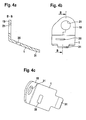
- the FIGS. 4 to 6 show the individual parts of the invention Holder - upper part, lower part and receiving part - in different views.
- the one designated by the letter a) View of Figures 4-6 is a side view or a Longitudinal section, denoted by b) view of Figures 4-6 is a side view and the c) designated view of Figures 4-6 is a top view.
- FIG. 1 shows a holder according to the invention in one Side view.
- the holder according to the invention consists of a Upper part 1, a lower part 3 and a receiving part 5.
- Das Receiving part 5, which made of an elastic material, such as For example, rubber is made, has a first Hole 7 and a second hole 9. In the first hole 7 becomes a first fuel line 15 and in the second Bore 9, a second fuel line 17 is held.
- the receiving part 5 can be opened.
- unfolded state (not shown) of the receiving part 5 the receiving part 5 via the first fuel line 15th and the second fuel line 17 are pushed. If so the receiving part 5 is folded back and thus the assumes the state shown in Figure 1, then the first fuel pipe 15 and the second fuel pipe 17 almost on all sides of the holes 7 and 9 of the receiving part. 5 enclosed.
- the first receiving part 5 made of an elastic material, such as rubber, are the first Fuel line 15 and the second fuel line safe fixed and protected against undue stress.
- the receiving part 5 in turn is of the upper part 1 and the Lower part 3 enclosed and is with these parts positively connected. This can, if the Holder according to the invention on a not shown Motor vehicle is attached, the first fuel line 15th and the second fuel line 17 are securely fixed. Because of the positive connection between receiving part 5, shell 1 and lower part 3, the receiving part 5 is not through the Vibrations of the vehicle engine from the upper part 1 and the Move out lower part 3. Therefore, the invention Holder for a fuel line also very reliable.
- the upper part 1 has a first flange 19 with an opening 21, while the lower part 3 a second flange 23 with an opening 25 has.
- closed state of the holder are aligned with the first opening 21 and the second opening 25, so that the holder with the help a screw (not shown) passing through first opening 21 and is plugged through second opening 25, at one also Motor vehicle, not shown, can be attached.
- the upper part 1 and the lower part 3 are by a Biegeverlappung 27 hinged together.
- the lower part 3 a fourth recess 29, through which a Lobe 31 of the upper part is inserted.
- the fourth recess 29 is not visible in FIG. In Figures 2 and 5 is the fourth recess 29, however, to recognize well.
- the receiving part 5 has a T-shaped fastening element 33 on.
- This fastener 33 is particularly good in the Figures 6a, b and c recognizable.
- first recess 35 is provided in the upper part 1. These first recess 35 is particularly good in Figures 2 and 4c visible, noticeable.
- a hook-shaped nose 37 and a Web 39 integrally formed are on the receiving part 5 .
- the hook-shaped nose 37 engages in a second recess 41 of the Lower part 3 a.
- the web 39 extends in closed Condition of the holder through a third recess 43 of the Bottom 3.
- the second recess 41 and the third Recess 43 are especially good in the different ones Views of Figure 5 seen.
- this preassembled holder on the motor vehicle (not shown), then it is only required to open the holder of the invention.
- Open the holder is characterized in that the lower part 3 at the Biegeverlappung 27 relative to the upper part 1 against the Turned clockwise. This will remove the first one Flange 19 of the upper part and the second flange 23 of the Parts 3 from each other.
- the receiving part 5 automatically opened because the rotational movement of the lower part 3 transmitted to the hook-shaped nose 27 of the receiving part 5 becomes. As a result, the opening 11 and the open Breakthrough 13 of the receiving part 5, so that the open Holder over the already existing in the vehicle Fuel lines 15 and 17 can be pushed.
- the holder is again closed, so that the first flange 19 and the second Flange 23 come into contact with each other.
- the first fuel pipe 15 and the second fuel pipe 17 held securely and the holder can by a screw, which is inserted through the openings 21 and 25, on easiest way to be firmly connected to the vehicle.
- the mounting of the holder on the motor vehicle is further characterized facilitates that by opening upper part 1 and Lower part 3 inevitably open the receiving part 5 is, without requiring further manipulation of the technician.
Landscapes
- Engineering & Computer Science (AREA)
- Mechanical Engineering (AREA)
- General Engineering & Computer Science (AREA)
- Life Sciences & Earth Sciences (AREA)
- Sustainable Development (AREA)
- Sustainable Energy (AREA)
- Chemical & Material Sciences (AREA)
- Combustion & Propulsion (AREA)
- Transportation (AREA)
- Cooling, Air Intake And Gas Exhaust, And Fuel Tank Arrangements In Propulsion Units (AREA)
- Supports For Pipes And Cables (AREA)
Applications Claiming Priority (2)
| Application Number | Priority Date | Filing Date | Title |
|---|---|---|---|
| DE2003146088 DE10346088B4 (de) | 2003-10-04 | 2003-10-04 | Halter für eine Kraftstoffleitung |
| DE10346088 | 2003-10-04 |
Publications (2)
| Publication Number | Publication Date |
|---|---|
| EP1521025A2 true EP1521025A2 (fr) | 2005-04-06 |
| EP1521025A3 EP1521025A3 (fr) | 2006-10-11 |
Family
ID=34306250
Family Applications (1)
| Application Number | Title | Priority Date | Filing Date |
|---|---|---|---|
| EP04022607A Withdrawn EP1521025A3 (fr) | 2003-10-04 | 2004-09-22 | Support d'un conduit de carburant |
Country Status (2)
| Country | Link |
|---|---|
| EP (1) | EP1521025A3 (fr) |
| DE (1) | DE10346088B4 (fr) |
Cited By (1)
| Publication number | Priority date | Publication date | Assignee | Title |
|---|---|---|---|---|
| US10005443B1 (en) | 2017-04-12 | 2018-06-26 | Teraflex, Inc. | Brake line anchor |
Families Citing this family (2)
| Publication number | Priority date | Publication date | Assignee | Title |
|---|---|---|---|---|
| DE102007020498B3 (de) * | 2007-04-30 | 2008-10-09 | Mtu Friedrichshafen Gmbh | Befestigungselement für eine Kraftstoffleitung |
| JP7205510B2 (ja) * | 2020-03-10 | 2023-01-17 | いすゞ自動車株式会社 | 燃料ホースの配索構造 |
Family Cites Families (7)
| Publication number | Priority date | Publication date | Assignee | Title |
|---|---|---|---|---|
| US2396925A (en) * | 1942-08-01 | 1946-03-19 | Adel Prec Products Corp | Subassembly conduit clip |
| DE3028998C2 (de) * | 1980-07-31 | 1984-02-02 | Adam Opel AG, 6090 Rüsselsheim | Haltevorrichtung |
| DE4141689C2 (de) * | 1991-12-18 | 1997-01-30 | Audi Ag | Vorrichtung zur Halterung einer Leitung an einer Wand eines Kraftfahrzeuges |
| DE4406574C1 (de) * | 1994-03-01 | 1995-12-21 | Rasmussen Gmbh | Rohrschelle |
| DE19735509C1 (de) * | 1997-08-16 | 1999-01-14 | Mecano Rapid Gmbh | Schelle zur Befestigung von Rohren |
| DE19939081C1 (de) * | 1999-08-18 | 2000-10-26 | Raymond A & Cie | Rohrleitungshalter |
| DE10110763A1 (de) * | 2001-03-07 | 2002-09-19 | Bayerische Motoren Werke Ag | Anordnung zur Halterung einer Kraftstoffleitung an einem Kraftfahrzeug |
-
2003
- 2003-10-04 DE DE2003146088 patent/DE10346088B4/de not_active Expired - Fee Related
-
2004
- 2004-09-22 EP EP04022607A patent/EP1521025A3/fr not_active Withdrawn
Cited By (1)
| Publication number | Priority date | Publication date | Assignee | Title |
|---|---|---|---|---|
| US10005443B1 (en) | 2017-04-12 | 2018-06-26 | Teraflex, Inc. | Brake line anchor |
Also Published As
| Publication number | Publication date |
|---|---|
| DE10346088A1 (de) | 2005-04-28 |
| EP1521025A3 (fr) | 2006-10-11 |
| DE10346088B4 (de) | 2009-11-05 |
Similar Documents
| Publication | Publication Date | Title |
|---|---|---|
| EP1979634B1 (fr) | Unité de montage destinée à un anneau de fixation d'une boucle de ceinture | |
| EP3973126B1 (fr) | Ferrure de meuble | |
| EP1852643A2 (fr) | Collier destiné à la fixation d'un objet tubulaire | |
| DE3300691A1 (de) | Ankerplattenanordnung fuer einen schliessbolzen | |
| DE10055426B4 (de) | Wischerlagergehäuse und Verfahren zum Herstellen eines Wischerlagergehäuses | |
| DE102011011072A1 (de) | Verbesserte Befestigung eines elektronischen Gerätes wie Impedanzwandler oder Verstärker an einer Fahrzeugkarosserie | |
| DE102005050222A1 (de) | Gelenkbeschlag für Kraftfahrzeugsitze und mit einer Ronde | |
| DE202009010054U1 (de) | Kraftfahrzeug mit einer Fronthaube | |
| EP0709267B1 (fr) | Dispositif d'essuie-glaces de véhicules automobiles | |
| DE102006029381A1 (de) | Steckverbinder an einem Bauteil, der in einem Loch einer Basis-Platte zu befestigen ist | |
| DE10147555B4 (de) | Vorrichtung zum Befestigen eines Abgas-Wärmeübertragers | |
| DE29812707U1 (de) | Befestigungsvorrichtung für flächige Bauteile | |
| DE602004003122T2 (de) | Positionier- und Befestigunseinrichtung für zwei mechanische Teile, Fahrzeuganordnung mit einer solchen Einrichtung und Fahrzeug mit einer solchen Anordnung | |
| EP1521025A2 (fr) | Support d'un conduit de carburant | |
| DE102004043561B4 (de) | Scharnierverstärkung für ein Kraftfahrzeugtürscharnier | |
| DE102006022382A1 (de) | Vorrichtung und Verfahren zur Befestigung eines Wischermotors an ein Wischergestänge | |
| DE10122458A1 (de) | Wischerarm, insbesondere für ein Kraftfahrzeug und Verfahren zur Herstellung eines solchen | |
| EP4505088B1 (fr) | Arrangement d'articulation de connexion | |
| EP2670934B1 (fr) | Serrure de véhicule à moteur | |
| DE202013103705U1 (de) | Hebelhakenverschluss für ein Bediengehäuse | |
| DE102006016238A1 (de) | Flanschverbindung | |
| EP0562157A1 (fr) | Fixation enfichable | |
| DE102004018552B3 (de) | Einrichtung zum Abkoppeln eines Fahrzeugbauteils von einem Karosserieteil | |
| DE102006053265A1 (de) | Dichtungsanordnung zur Abdichtung einer Durchgangsöffnung und Montageverfahren | |
| DE19958158B4 (de) | Anordnung zur Befestigung eines Montageteils an einem Wandabschnitt eines Blechkörpers |
Legal Events
| Date | Code | Title | Description |
|---|---|---|---|
| PUAI | Public reference made under article 153(3) epc to a published international application that has entered the european phase |
Free format text: ORIGINAL CODE: 0009012 |
|
| AK | Designated contracting states |
Kind code of ref document: A2 Designated state(s): AT BE BG CH CY CZ DE DK EE ES FI FR GB GR HU IE IT LI LU MC NL PL PT RO SE SI SK TR |
|
| AX | Request for extension of the european patent |
Extension state: AL HR LT LV MK |
|
| PUAL | Search report despatched |
Free format text: ORIGINAL CODE: 0009013 |
|
| AK | Designated contracting states |
Kind code of ref document: A3 Designated state(s): AT BE BG CH CY CZ DE DK EE ES FI FR GB GR HU IE IT LI LU MC NL PL PT RO SE SI SK TR |
|
| AX | Request for extension of the european patent |
Extension state: AL HR LT LV MK |
|
| AKX | Designation fees paid | ||
| STAA | Information on the status of an ep patent application or granted ep patent |
Free format text: STATUS: THE APPLICATION IS DEEMED TO BE WITHDRAWN |
|
| 18D | Application deemed to be withdrawn |
Effective date: 20070412 |
|
| REG | Reference to a national code |
Ref country code: DE Ref legal event code: 8566 |