EP1521054B1 - Vorrichtung zur Halterung von Karosserieteilen in einer Vermessungsposition - Google Patents
Vorrichtung zur Halterung von Karosserieteilen in einer Vermessungsposition Download PDFInfo
- Publication number
- EP1521054B1 EP1521054B1 EP04016900A EP04016900A EP1521054B1 EP 1521054 B1 EP1521054 B1 EP 1521054B1 EP 04016900 A EP04016900 A EP 04016900A EP 04016900 A EP04016900 A EP 04016900A EP 1521054 B1 EP1521054 B1 EP 1521054B1
- Authority
- EP
- European Patent Office
- Prior art keywords
- car body
- body part
- measuring
- supporting structure
- devices
- Prior art date
- Legal status (The legal status is an assumption and is not a legal conclusion. Google has not performed a legal analysis and makes no representation as to the accuracy of the status listed.)
- Expired - Lifetime
Links
- 239000000523 sample Substances 0.000 abstract description 7
- XAGFODPZIPBFFR-UHFFFAOYSA-N aluminium Chemical compound [Al] XAGFODPZIPBFFR-UHFFFAOYSA-N 0.000 abstract description 2
- 229910052782 aluminium Inorganic materials 0.000 abstract description 2
- 238000011326 mechanical measurement Methods 0.000 abstract 1
- 238000004519 manufacturing process Methods 0.000 description 3
- 238000009434 installation Methods 0.000 description 2
- 238000010276 construction Methods 0.000 description 1
- 238000007689 inspection Methods 0.000 description 1
- 230000013011 mating Effects 0.000 description 1
Images


Classifications
-
- G—PHYSICS
- G01—MEASURING; TESTING
- G01B—MEASURING LENGTH, THICKNESS OR SIMILAR LINEAR DIMENSIONS; MEASURING ANGLES; MEASURING AREAS; MEASURING IRREGULARITIES OF SURFACES OR CONTOURS
- G01B5/00—Measuring arrangements characterised by the use of mechanical techniques
- G01B5/0002—Arrangements for supporting, fixing or guiding the measuring instrument or the object to be measured
- G01B5/0004—Supports
-
- G—PHYSICS
- G01—MEASURING; TESTING
- G01B—MEASURING LENGTH, THICKNESS OR SIMILAR LINEAR DIMENSIONS; MEASURING ANGLES; MEASURING AREAS; MEASURING IRREGULARITIES OF SURFACES OR CONTOURS
- G01B5/00—Measuring arrangements characterised by the use of mechanical techniques
- G01B5/004—Measuring arrangements characterised by the use of mechanical techniques for measuring coordinates of points
Definitions
- the invention relates to a device for holding body parts in a Verodersposition, with a support structure are formed on the receiving seats for to be held in the Verresssposition body part, and with additional facilities for the expansion of the mounting device to a Tastmess wornen comprehensive measuring device, wherein the additional devices (8a -10a) are releasably connectable to the support structure.
- Holding devices of this type are used in vehicle construction, e.g. used in the context of body development. Due to the receiving seats of the support structure, the body part can hold deformation-free in a predetermined position, so that it is e.g. can be measured by a coordinate measuring machine.
- a device for measuring car bodies in which the body is held on a base plate by support and a post.
- the body is measured by means of adapters which are brought into contact with the body and a measuring device and extend from the measuring point to a location accessible to the measuring device.
- the invention has for its object to provide a new, variable usable as such devices according to the prior art device.
- the object is achieved by a device according to claim 1.
- a stop corresponding to another, adjacent to said body part Karossemeteil produce bodywork of a vehicle body, said gauge stop, in particular the adjacent edge of the further Karossemeteils at least partially replicates.
- the invention is accordingly a modular system whose basic component is provided with receiving seats, prepared for the installation of additional equipment support structure.
- the area required for scanning may, in particular, be the upper edge of a body part which closes the body downwards.
- the support structure consists of interconnected profiles with undercut grooves and the additional equipment can be attached to the support structure with the help of engaging grooves in the nuts.
- the auxiliary devices have connectable arms with the support structure for holding the stop or the keying devices.
- the support structure and / or the additional devices have mating holes or / and seats for accurately fitting the additional devices to the supporting structure. Through these holes, the gauge can be reproduced exactly and install the additional equipment with little installation effort to the support structure.
- the tactile measuring devices may be mechanical dial gauges and / or electrical measuring probes.
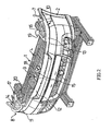
- a supporting structure 1 of a holding device for a body part 2 to be measured with the aid of a coordinate measuring machine consists of aluminum supporting profiles 3, which have a cross-sectionally square cross-section and grooves 4 undercut on each of the four sides 2.
- the body part accommodating seats are formed, which are arranged so that the body part is held without deformation by the device.
- the position of the seats can be adjusted to a limited extent.
- Tension levers 7 allow locking of adjusted positions.
- FIG. 2 shown variant of the device to a doctrine are mounted on the support structure 1 additional devices 8 to 10, each having a stop 11,12 and 13 and a stop associated with the boom 14,15 and 16 respectively.
- the arms 14 to 16 are connected at their end facing away from the stop with the support structure 1.
- the stops 11 to 13 form the lower edge of a further body part, which adjoins the upper edge of the body part and are housed in which vehicle headlight.
- a connecting element 17,18 or 19 For attachment of the additional devices 8 to 10 on the support structure is in each case a connecting element 17,18 or 19, each of which has a base plate 20, which is screwed with arranged in the grooves 4 nuts (not shown).
- the additional equipment can be mounted accurately with little effort.
- dowel pins and fitting holes are provided.
- the expansion variant described can be used in the further body development, during which it usually comes to changes in the prototype body part.
- the gauge formed by the stops ensures the fitting of changed parts in the rest of the body.
- the additional devices 8a to 10a each have a holder 21,22 or 23 for Tastmess wornen, wherein the holder is attached via a boom 14a, 15a and 16a and a connecting element 17a, 18a and 19a to the support structure 1.
- electrical measuring probes 24 and mechanical dial gauges 25 are partially shown as touch probe devices.
- Tastroye 26 of the probe 24 and dial gauges 25 touch the upper edge of the body part 2, which in the expansion variant as teaching according to Fig. 2 comes to rest against the attacks 11,12 and 13 comes.
- Fig. 3 described expansion variant can be used in production for series inspection of the body part.
- one and the same device can thus be used from the prototype phase of the development and finally transferred into production as a series control device.
Landscapes
- Physics & Mathematics (AREA)
- General Physics & Mathematics (AREA)
- A Measuring Device Byusing Mechanical Method (AREA)
- Details Of Measuring And Other Instruments (AREA)
- Clamps And Clips (AREA)
- Load-Engaging Elements For Cranes (AREA)
- Automobile Manufacture Line, Endless Track Vehicle, Trailer (AREA)
Description
- Die Erfindung betrifft eine Vorrichtung zur Halterung von Karosserieteilen in einer Vermessungsposition, mit einer Tragkonstruktion, an der Aufnahmesitze für das in der Vermessungsposition zu haltende Karosserieteil gebildet sind, und mit Zusatzeinrichtungen für den Ausbau der Halterungsvorrichtung zu einer Tastmesseinrichtungen umfassenden Messvorrichtung, wobei die Zusatzeinrichtungen (8a-10a) lösbar mit der Tragkonstruktion verbindbar sind.
- Halterungsvorrichtungen solcher Art kommen im Fahrzeugbau z.B. im Rahmen der Karosserieentwicklung zum Einsatz. Durch die Aufnahmesitze der Tragkonstruktion lässt sich das Karosserieteil verformungsfrei in einer vorbestimmten Position halten, so dass es sich z.B. durch eine Koordinatenmessmaschine vermessen lässt.
- Aus der
DE 31 21 579 A1 geht eine in der Serienkontrolle von Fahrzeugkarosserien einsetzbare Messlehre hervor, die eine Hatterungsvorrichtung der eingangs erwähnten Art umfasst. Auf einem eine Karosserie in definierter Position aufnehmenden und halternden Messrahmen sind über Tragkonsolen mehrere Tastmesseinrichtungen befestigt, die mit ihrer Tastspitze jeweils einem Messpunkt zugeordnet sind. Die Tastspitze kann in eine Messstellung auf das Messobjekt zu bewegt und in eine Wartestellung zurückgezogen werden. - In der
GB 1 391 328 A - Der Erfindung liegt die Aufgabe zugrunde, eine neue, variabler als solche Vorrichtungen nach dem Stand der Technik einsetzbare Vorrichtung zu schaffen.
- Die Aufgabe wird durch eine Vorrichtung nach Anspruch 1 gelöst.
- Durch die Zusatzeinrichtung zur Bildung der Lehre lässt sich ein Anschlag entsprechend einem weiteren, an das genannte Karosserieteil angrenzenden Karossemeteil einer Fahrzeug Karosserie herstellen, wobei dieser Lehrenanschlag insbesondere den angrenzenden Rand des weiteren Karossemeteils wenigstens teilweise nachbildet. Eine solche Lehre sichert während weiterer Entwicklungsphasen, dass sich geänderte Prototypkarosserieteile stets passgenau in die übrige karosserie einfügen.
- Gegenstand der Erfindung ist demgemäss ein Baukastensystem, dessen Grundbestandteil die mit Aufnahmesitzen versehene, zur Montage von Zusatzeinrichtungen vorbereitete Tragkonstruktion ist. Vorteilhaft lässt sich so ein und dieselbe Tragkonstruktion von der Prototypphase an über die weitere Karosserieentwicklung bis hin zur Serienfertigung verwenden und den jeweiligen Anforderungen entsprechend aus- und umbauen. Entsprechend verringert sich der für die Bereitstellung von Messmitteln erforderliche Aufwand.
- Bei dem zur Abtastung erforderlichen Bereich kann es sich insbesondere um den oberen Rand eines Karosserieteils handeln, das die Karosserie nach unten abschließt.
- In weiterer vorteilhafter Ausgestaltung der Erfindung besteht die Tragkonstruktion aus miteinander verbundenen Profilen mit hinterschnittenen Nuten und die Zusatzeinrichtungen lassen sich an der Tragkonstruktion mit Hilfe in die Nuten eingreifender Nutensteine befestigen.
- Vorzugsweise weisen die Zusatzeinrichtungen mit der Tragkonstruktion verbindbare Ausleger zum Halten des Anschlags oder der Tastmesseinrichtungen auf.
- Insbesondere weisen die Tragkonstruktion und/oder die Zusatzeinrichtungen Passbohrungen oder/und Sitze zur passgenauen Montage der Zusatzeinrichtungen an der Tragkonstruktion auf. Durch diese Bohrungen lassen sich das Lehrenmaß genau reproduzieren und die Zusatzeinrichtungen mit geringem Montageaufwand an der Tragkonstruktion anbringen.
- Bei den Tastmesseinrichtungen kann es sich um mechanische Messuhren oder/und elektrische Messtaster handeln.
- Die Erfindung soll nun anhand eines Ausführungsbeispiels und der beiliegenden, sich auf dieses Ausführungsbeispiel beziehenden Zeichnungen näher erläutert werden. Es zeigen:
- Fig. 1
- eine Vorrichtung ohne Zusatzeinrichtungen,
- Fig. 2
- die Vorrichtung von
Fig. 1 ausgebaut zu einer Lehre, und - Fig. 3
- die Vorrichtung von
Fig. 1 ausgebaut zu einer Messvorrichtung. - Eine Tragkonstruktion 1 einer Haltevorrichtung für ein mit Hilfe einer Koordinatenmessmaschine auszumessendes Karosserieteil 2 besteht aus Aluminiumtragprofilen 3, die einen im Umriss quadratischen Querschnitt und an jeder der vier Seiten 2 hinterschnittene Nuten 4 aufweisen.
- An der Tragkonstruktion 1 sind an verschiedenen Stellen, z.B. bei 5 und 6, das Karosserieteil aufnehmende Sitze gebildet, die so angeordnet sind, dass das Karosserieteil verformungsfrei durch die Vorrichtung gehalten wird. Die Position der Sitze lässt sich in begrenztem Umfang verstellen. Spannhebel 7 erlauben eine Arretierung eingestellter Positionen.
- Das an der Tragkonstruktion 1 gehaltene Karosserieteil 2, das in dem hier beschriebenen Ausführungsbeispiel ein Frontteil eines Karosserie-Prototyps ist, lässt sich mit Hilfe einer Koordinatenmessmaschine vermessen.
- In einer in
Fig. 2 gezeigten Ausbauvariante der Vorrichtung zu einer Lehre sind an der Tragkonstruktion 1 Zusatzeinrichtungen 8 bis 10 montiert, die jeweils einen Anschlag 11,12 bzw. 13 und einen mit dem Anschlag verbundenen Ausleger 14,15 bzw. 16 aufweisen. Die Ausleger 14 bis 16 sind an ihrem dem Anschlag abgewandten Ende mit der Tragkonstruktion 1 verbunden. Die Anschläge 11 bis 13 bilden den unteren Rand eines weiteren Karosserieteils nach, welches an den oberen Rand des Karosserieteils angrenzt und in welchem Fahrzeugscheinwerfer untergebracht sind. - Zur Befestigung der Zusatzeinrichtungen 8 bis 10 an der Tragkonstruktion dient jeweils ein Verbindungselement 17,18 bzw. 19, von denen jedes eine Grundplatte 20 aufweist, die mit in den Nuten 4 angeordneten Nutensteinen (nicht gezeigt) verschraubt ist.
- Die Zusatzeinrichtungen lassen sich mit geringem Aufwand positionsgenau montieren. Hierzu sind (in den Figuren nicht sichtbare) Passstifte und Passbohrungen vorgesehen.
- Die beschriebene Ausbauvariante lässt sich bei der weiteren Karosserieentwicklung einsetzen, während der es gewöhnlich zu Änderungen des Prototyp-Karosserieteils kommt. Die durch die Anschläge gebildete Lehre sichert die Einpassung geänderter Teile in die übrige Karosserie.
- In der in
Fig. 3 gezeigten Ausbauvariante, in der die Karosserieteilhalterung zu einer Messvorrichtung ausgebaut ist, sind an der Tragkonstruktion 1 Zusatzeinrichtungen 8a bis 10a in ähnlicher Weise wie bei der Ausbauvariante vonFig. 2 angebracht. - Die Zusatzeinrichtungen 8a bis 10a weisen jeweils einen Halter 21,22 bzw. 23 für Tastmesseinrichtungen auf, wobei der Halter über einen Ausleger 14a, 15a bzw. 16a und ein Verbindungselement 17a,18a bzw. 19a an der Tragkonstruktion 1 befestigt ist.
- Beispielhaft sind als Tastmesseinrichtungen teilweise elektrische Messtaster 24 und mechanische Messuhren 25 gezeigt. Taststifte 26 der Messtaster 24 bzw. Messuhren 25 berühren den oberen Rand des Karosserieteils 2, welcher in der Ausbauvariante als Lehre gemäß
Fig. 2 zur Anlage gegen die Anschläge 11,12 und 13 kommt. - Die in
Fig. 3 beschriebene Ausbauvariante lässt sich in der Fertigung zur Serienkontrolle des Karosserieteils einsetzen. Vorteilhaft lässt sich somit ein und dieselbe Vorrichtung von der Prototypphase der Entwicklung an verwenden und schließlich als Serienkontrollvorrichtung in die Fertigung überführen.
Claims (5)
- Vorrichtung zur Halterung von Karosserieteilen (2) in einer Vermessungsposition, mit einer Tragkonstruktion (1), an der Aufnahmesitze (5,6) für das in der Vermessungsposition zu haltende Karosserieteil (2) gebildet sind, und
mit Zusatzeinrichtungen (8a-10a) für den Ausbau der Halterungsvorrichtung zu einer Tastmesseinrichtungen (24,25) umfassenden Messvorrichtung, wobei,
die Zusatzeinrichtungen (8a-10a) lösbar mit der Tragkonstruktion verbindbar sind, dadurch gekennzeichnet dass die Vorrichtung anstelle der genannten Zusatzeinrichtungen (8a-10a) mit der Tragkonstruktion (1) lösbar verbindbare weitere Zusatzeinrichtungen (8-10) für den Ausbau der Halterungseinrichtung zu einer Lehre mit einem Anschlag (11-13) aufweist, wobei der Anschlag zur Anlage gegen einen durch die Tastmesseinrichtungen (24,25)der Messlehre abgetasteten Bereich des Karosserieteils (2) vorgesehen ist und einen an das Karosserieteil (2) angrenzenden Rand eines weiteren Teils der Fahrzeugkarosserie wenigstens teilweise nachbildet. - Vorrichtung nach Anspruch 1,
dadurch gekennzeichnet,
dass der zur Abtastung vorgesehene Bereich den oberen Rand des Karosserieteils (2) umfasst. - Vorrichtung nach Anspruch 1 oder 2,
dadurch gekennzeichnet,
dass die Tragkonstruktion (1) miteinander verbundene Profile (2) mit hinterschnittenen Längsnuten (4) umfasst und die Zusatzeinrichtungen (8-10; 8a-10a) sich an der Tragkonstruktion (1) mit Hilfe in die Nuten (4) eingreifender Nutensteine befestigen lassen. - Vorrichtung nach einem der Ansprüche 1 bis 3,
dadurch gekennzeichnet,
dass die Zusatzeinrichtungen (8-10; 8a-00a) mit der Tragkonstruktion (1) verbindbare Ausleger (14-16) zum Halten des Anschlags (11-13) oder der Tastmesseinrichtungen (24,25) umfassen. - Vorrichtung nach einem der Ansprüche 1 bis 4,
dadurch gekennzeichnet,
dass als Tastmesseinrichtungen mechanische Messuhren (25) und/oder elektrische Messtaster (24) vorgesehen sind.
Applications Claiming Priority (2)
| Application Number | Priority Date | Filing Date | Title |
|---|---|---|---|
| DE10345284A DE10345284A1 (de) | 2003-09-30 | 2003-09-30 | Vorrichtung zur Halterung von Karosserieteilen in einer Vermessungsposition |
| DE10345284 | 2003-09-30 |
Publications (3)
| Publication Number | Publication Date |
|---|---|
| EP1521054A2 EP1521054A2 (de) | 2005-04-06 |
| EP1521054A3 EP1521054A3 (de) | 2006-11-02 |
| EP1521054B1 true EP1521054B1 (de) | 2010-09-08 |
Family
ID=34306144
Family Applications (1)
| Application Number | Title | Priority Date | Filing Date |
|---|---|---|---|
| EP04016900A Expired - Lifetime EP1521054B1 (de) | 2003-09-30 | 2004-07-17 | Vorrichtung zur Halterung von Karosserieteilen in einer Vermessungsposition |
Country Status (4)
| Country | Link |
|---|---|
| EP (1) | EP1521054B1 (de) |
| AT (1) | ATE480750T1 (de) |
| DE (2) | DE10345284A1 (de) |
| ES (1) | ES2358469T3 (de) |
Cited By (1)
| Publication number | Priority date | Publication date | Assignee | Title |
|---|---|---|---|---|
| CN103817627A (zh) * | 2014-03-06 | 2014-05-28 | 重庆赫杰精密机械有限公司 | 一种白车身检具承载装置 |
Families Citing this family (2)
| Publication number | Priority date | Publication date | Assignee | Title |
|---|---|---|---|---|
| DE202009015384U1 (de) | 2009-11-13 | 2010-03-11 | Invenio Gmbh Engineering Services | Spanneinheit zum positionsgenauen Aufspannen von Werkstücken, Vorrichtung zur Positionierung einer solchen Spanneinheit sowie Aufspannsystem |
| CN104374247B (zh) * | 2014-10-20 | 2017-02-15 | 湖南湖大艾盛汽车技术开发有限公司 | 一种模块化汽车发动机罩检测装置 |
Family Cites Families (4)
| Publication number | Priority date | Publication date | Assignee | Title |
|---|---|---|---|---|
| GB1391328A (en) | 1972-05-30 | 1975-04-23 | Pressed Steel Fisher Ltd | Checking fixtures for dimensions of vehicle bodies |
| DE3121579C2 (de) | 1981-05-30 | 1983-07-14 | Daimler-Benz Ag, 7000 Stuttgart | In den drei Raumrichtungen messende Meßtasteinrichtung für Meßlehren |
| US5207002A (en) * | 1992-03-19 | 1993-05-04 | Humblet Steven V | Method and system for vehicle frame alignment |
| DE19921340A1 (de) * | 1999-05-08 | 2000-03-09 | Manfred Taubenmann | Adapter-Transformations-System mit Justierfix-Positionsbolzen und -büchsen als Baukastenelemente für Aufspanntechnik zum Messen und Feinabstimmen für Karosserie- und ähnliche Teile |
-
2003
- 2003-09-30 DE DE10345284A patent/DE10345284A1/de not_active Withdrawn
-
2004
- 2004-07-17 EP EP04016900A patent/EP1521054B1/de not_active Expired - Lifetime
- 2004-07-17 AT AT04016900T patent/ATE480750T1/de active
- 2004-07-17 ES ES04016900T patent/ES2358469T3/es not_active Expired - Lifetime
- 2004-07-17 DE DE502004011634T patent/DE502004011634D1/de not_active Expired - Lifetime
Cited By (1)
| Publication number | Priority date | Publication date | Assignee | Title |
|---|---|---|---|---|
| CN103817627A (zh) * | 2014-03-06 | 2014-05-28 | 重庆赫杰精密机械有限公司 | 一种白车身检具承载装置 |
Also Published As
| Publication number | Publication date |
|---|---|
| DE502004011634D1 (de) | 2010-10-21 |
| EP1521054A2 (de) | 2005-04-06 |
| ES2358469T3 (es) | 2011-05-11 |
| ATE480750T1 (de) | 2010-09-15 |
| DE10345284A1 (de) | 2005-04-21 |
| EP1521054A3 (de) | 2006-11-02 |
Similar Documents
| Publication | Publication Date | Title |
|---|---|---|
| DE69800510T2 (de) | Vorrichtung zur Kraftfahrzeugmontage mit einem System zur Verformungsauffindung, und Montageverfahren dafür | |
| DE3207714C2 (de) | Vorrichtung zum Messen und Prüfen von Motorradrahmen | |
| DE102007032557B4 (de) | Vorrichtung zum Testen von elektronischen Bauelementen, insbesondere IC's, mit innerhalb einer Drucktestkammer angeordnetem Abdichtboard | |
| DE2914333A1 (de) | Vorrichtung zur nachpruefung evtl. verformungen einer kraftfahrzeug- karosserie | |
| DE102013014273A1 (de) | Parallelarmroboter | |
| EP2416132B1 (de) | Waage mit Anzeige- und Bedieneinheit | |
| EP0802393A2 (de) | Messeinrichtung zur Vermessung von Werkstücken | |
| DE102009053874A1 (de) | Roboter zur automatischen 3D-Vermessung und Verfahren | |
| DE102004057776A1 (de) | Lagekorrektureinrichtung zur Korrektur der Position eines Bauelementehalters für elektronische Bauelemente | |
| EP1260304B1 (de) | Werkstückhalter | |
| DE19856126A1 (de) | Positioniervorrichtung zum Ausrichten eines an einer Fahrzeugkarosserie anordenbaren Bauteiles | |
| EP1521054A2 (de) | Vorrichtung zur Halterung von Karosserieteilen in einer Vermessungsposition | |
| DE102008048081A1 (de) | Verfahren zur Prüfung elektronischer Bauelemente einer Wiederholstruktur unter definierten thermischen Bedingungen | |
| DE19850259B4 (de) | Vorrichtung zur Vermessung von Bauteilen | |
| DE102005046154B4 (de) | Messvorrichtung und Messsystem zum Inspizieren einer Oberfläche eines Substrates | |
| EP1571411B1 (de) | Messeinrichtung | |
| DE19858638A1 (de) | Meßaufnahmerahmen | |
| DE102020007732A1 (de) | Befestigungsvorrichtung zur Befestigung eines elektrischen Energiespeichers für ein Fahrzeug an einem Trägerschlitten | |
| DE202010007546U1 (de) | Pneumatische Richtvorrichtung | |
| DE102013112188A1 (de) | Verfahren zur Montage von Bauteilen mit Hilfe eines Koordinatenmessgeräts | |
| DE202013101614U1 (de) | Halter zum Niederhalten oder Auflegen einer zu prüfenden Platine in einer Prüfanordnung | |
| DE102007024905A1 (de) | Verfahren zur Kalibrierung eines Meßsystems zur Messung der Achsgeometrie eines Fahrzeugs und zugehörige Vorrichtung | |
| DE19957635A1 (de) | Anordnung von Fahrzeugteilen an einem Koordinatenmeßstand | |
| DE102018131880A1 (de) | Lehre zum Qualifizieren des Zustands einer Turbinenschaufel | |
| DE102015014932B4 (de) | Fertigungssystem für ein Kraftfahrzeugbauteil sowie Verfahren zum Betreiben eines Fertigungssystems |
Legal Events
| Date | Code | Title | Description |
|---|---|---|---|
| PUAI | Public reference made under article 153(3) epc to a published international application that has entered the european phase |
Free format text: ORIGINAL CODE: 0009012 |
|
| AK | Designated contracting states |
Kind code of ref document: A2 Designated state(s): AT BE BG CH CY CZ DE DK EE ES FI FR GB GR HU IE IT LI LU MC NL PL PT RO SE SI SK TR |
|
| AX | Request for extension of the european patent |
Extension state: AL HR LT LV MK |
|
| PUAL | Search report despatched |
Free format text: ORIGINAL CODE: 0009013 |
|
| AK | Designated contracting states |
Kind code of ref document: A3 Designated state(s): AT BE BG CH CY CZ DE DK EE ES FI FR GB GR HU IE IT LI LU MC NL PL PT RO SE SI SK TR |
|
| AX | Request for extension of the european patent |
Extension state: AL HR LT LV MK |
|
| RIC1 | Information provided on ipc code assigned before grant |
Ipc: G01B 3/00 20060101ALI20060927BHEP Ipc: G01B 7/00 20060101ALI20060927BHEP Ipc: G01B 5/00 20060101AFI20050117BHEP |
|
| 17P | Request for examination filed |
Effective date: 20070323 |
|
| 17Q | First examination report despatched |
Effective date: 20070419 |
|
| AKX | Designation fees paid |
Designated state(s): AT DE ES FR IT |
|
| GRAP | Despatch of communication of intention to grant a patent |
Free format text: ORIGINAL CODE: EPIDOSNIGR1 |
|
| GRAS | Grant fee paid |
Free format text: ORIGINAL CODE: EPIDOSNIGR3 |
|
| GRAA | (expected) grant |
Free format text: ORIGINAL CODE: 0009210 |
|
| AK | Designated contracting states |
Kind code of ref document: B1 Designated state(s): AT DE ES FR IT |
|
| REF | Corresponds to: |
Ref document number: 502004011634 Country of ref document: DE Date of ref document: 20101021 Kind code of ref document: P |
|
| REG | Reference to a national code |
Ref country code: ES Ref legal event code: FG2A Ref document number: 2358469 Country of ref document: ES Kind code of ref document: T3 Effective date: 20110428 |
|
| PLBE | No opposition filed within time limit |
Free format text: ORIGINAL CODE: 0009261 |
|
| STAA | Information on the status of an ep patent application or granted ep patent |
Free format text: STATUS: NO OPPOSITION FILED WITHIN TIME LIMIT |
|
| 26N | No opposition filed |
Effective date: 20110609 |
|
| REG | Reference to a national code |
Ref country code: DE Ref legal event code: R097 Ref document number: 502004011634 Country of ref document: DE Effective date: 20110609 |
|
| REG | Reference to a national code |
Ref country code: AT Ref legal event code: MM01 Ref document number: 480750 Country of ref document: AT Kind code of ref document: T Effective date: 20110717 |
|
| PG25 | Lapsed in a contracting state [announced via postgrant information from national office to epo] |
Ref country code: AT Free format text: LAPSE BECAUSE OF NON-PAYMENT OF DUE FEES Effective date: 20110717 |
|
| REG | Reference to a national code |
Ref country code: DE Ref legal event code: R082 Ref document number: 502004011634 Country of ref document: DE Representative=s name: PATENTANWAELTE DR.-ING. W. BERNHARDT DR. R. BE, DE Effective date: 20131024 Ref country code: DE Ref legal event code: R081 Ref document number: 502004011634 Country of ref document: DE Owner name: CARL ZEISS FIXTURE SYSTEMS GMBH, DE Free format text: FORMER OWNER: JUNKER & PARTNER GMBH, 66636 THOLEY, DE Effective date: 20131024 Ref country code: DE Ref legal event code: R082 Ref document number: 502004011634 Country of ref document: DE Representative=s name: PATENTANWAELTE BERNHARDT/WOLFF PARTNERSCHAFT, DE Effective date: 20131024 Ref country code: DE Ref legal event code: R082 Ref document number: 502004011634 Country of ref document: DE Representative=s name: PATENTANWAELTE BERNHARDT/WOLFF PARTNERSCHAFT M, DE Effective date: 20131024 |
|
| REG | Reference to a national code |
Ref country code: DE Ref legal event code: R082 Ref document number: 502004011634 Country of ref document: DE Representative=s name: PATENTANWAELTE BERNHARDT/WOLFF PARTNERSCHAFT, DE Ref country code: DE Ref legal event code: R082 Ref document number: 502004011634 Country of ref document: DE Representative=s name: PATENTANWAELTE BERNHARDT/WOLFF PARTNERSCHAFT M, DE |
|
| REG | Reference to a national code |
Ref country code: FR Ref legal event code: PLFP Year of fee payment: 12 |
|
| PGFP | Annual fee paid to national office [announced via postgrant information from national office to epo] |
Ref country code: ES Payment date: 20150723 Year of fee payment: 12 Ref country code: DE Payment date: 20150706 Year of fee payment: 12 |
|
| PGFP | Annual fee paid to national office [announced via postgrant information from national office to epo] |
Ref country code: FR Payment date: 20150703 Year of fee payment: 12 |
|
| PGFP | Annual fee paid to national office [announced via postgrant information from national office to epo] |
Ref country code: IT Payment date: 20150728 Year of fee payment: 12 |
|
| REG | Reference to a national code |
Ref country code: DE Ref legal event code: R119 Ref document number: 502004011634 Country of ref document: DE |
|
| PG25 | Lapsed in a contracting state [announced via postgrant information from national office to epo] |
Ref country code: FR Free format text: LAPSE BECAUSE OF NON-PAYMENT OF DUE FEES Effective date: 20160801 Ref country code: DE Free format text: LAPSE BECAUSE OF NON-PAYMENT OF DUE FEES Effective date: 20170201 |
|
| REG | Reference to a national code |
Ref country code: FR Ref legal event code: ST Effective date: 20170331 |
|
| PG25 | Lapsed in a contracting state [announced via postgrant information from national office to epo] |
Ref country code: IT Free format text: LAPSE BECAUSE OF NON-PAYMENT OF DUE FEES Effective date: 20160717 |
|
| PG25 | Lapsed in a contracting state [announced via postgrant information from national office to epo] |
Ref country code: ES Free format text: LAPSE BECAUSE OF NON-PAYMENT OF DUE FEES Effective date: 20160718 |
|
| REG | Reference to a national code |
Ref country code: ES Ref legal event code: FD2A Effective date: 20181130 |