EP1521095A1 - Aimant superconducteur - Google Patents
Aimant superconducteur Download PDFInfo
- Publication number
- EP1521095A1 EP1521095A1 EP04256057A EP04256057A EP1521095A1 EP 1521095 A1 EP1521095 A1 EP 1521095A1 EP 04256057 A EP04256057 A EP 04256057A EP 04256057 A EP04256057 A EP 04256057A EP 1521095 A1 EP1521095 A1 EP 1521095A1
- Authority
- EP
- European Patent Office
- Prior art keywords
- coils
- coil
- superconducting
- counteracting
- main
- Prior art date
- Legal status (The legal status is an assumption and is not a legal conclusion. Google has not performed a legal analysis and makes no representation as to the accuracy of the status listed.)
- Granted
Links
- 230000005291 magnetic effect Effects 0.000 claims abstract description 42
- 239000002826 coolant Substances 0.000 claims abstract description 15
- 238000001816 cooling Methods 0.000 claims description 15
- 238000005481 NMR spectroscopy Methods 0.000 claims 1
- 238000003384 imaging method Methods 0.000 abstract description 14
- 230000006835 compression Effects 0.000 abstract description 7
- 238000007906 compression Methods 0.000 abstract description 7
- 238000002595 magnetic resonance imaging Methods 0.000 description 6
- 239000000463 material Substances 0.000 description 6
- XEEYBQQBJWHFJM-UHFFFAOYSA-N Iron Chemical compound [Fe] XEEYBQQBJWHFJM-UHFFFAOYSA-N 0.000 description 2
- 206010040007 Sense of oppression Diseases 0.000 description 2
- -1 for example Substances 0.000 description 2
- 230000003068 static effect Effects 0.000 description 2
- 238000003745 diagnosis Methods 0.000 description 1
- 230000005294 ferromagnetic effect Effects 0.000 description 1
- 229910052734 helium Inorganic materials 0.000 description 1
- 239000001307 helium Substances 0.000 description 1
- SWQJXJOGLNCZEY-UHFFFAOYSA-N helium atom Chemical compound [He] SWQJXJOGLNCZEY-UHFFFAOYSA-N 0.000 description 1
- 239000011810 insulating material Substances 0.000 description 1
- 229910052742 iron Inorganic materials 0.000 description 1
- 239000007788 liquid Substances 0.000 description 1
- 239000000126 substance Substances 0.000 description 1
Images
Classifications
-
- G—PHYSICS
- G01—MEASURING; TESTING
- G01R—MEASURING ELECTRIC VARIABLES; MEASURING MAGNETIC VARIABLES
- G01R33/00—Arrangements or instruments for measuring magnetic variables
- G01R33/20—Arrangements or instruments for measuring magnetic variables involving magnetic resonance
- G01R33/28—Details of apparatus provided for in groups G01R33/44 - G01R33/64
- G01R33/38—Systems for generation, homogenisation or stabilisation of the main or gradient magnetic field
- G01R33/3806—Open magnet assemblies for improved access to the sample, e.g. C-type or U-type magnets
-
- G—PHYSICS
- G01—MEASURING; TESTING
- G01R—MEASURING ELECTRIC VARIABLES; MEASURING MAGNETIC VARIABLES
- G01R33/00—Arrangements or instruments for measuring magnetic variables
- G01R33/20—Arrangements or instruments for measuring magnetic variables involving magnetic resonance
- G01R33/28—Details of apparatus provided for in groups G01R33/44 - G01R33/64
- G01R33/38—Systems for generation, homogenisation or stabilisation of the main or gradient magnetic field
- G01R33/381—Systems for generation, homogenisation or stabilisation of the main or gradient magnetic field using electromagnets
- G01R33/3815—Systems for generation, homogenisation or stabilisation of the main or gradient magnetic field using electromagnets with superconducting coils, e.g. power supply therefor
Definitions
- the present invention relates to a superconducting magnet apparatus suitable for a magnetic filed generation source of a magnetic resonance imaging apparatus.
- a superconducting magnet apparatus used as a magnetic field generation source of a magnetic resonance imaging for example, comprises a pair of cooling medium chamber enclosing a plurality of superconducting coils having different diameter and formed annularly, a pair of vacuum chamber enclosing each cooling medium chamber, and a connecting bar connecting each of the vacuum chambers so as to form a magnetic field space(measuring space) between the pair of vacuum chamber.
- Such apparatus is disclosed in Japanese Laid-open Patent Publication Hei-9-153408 and US patent 6580346B1 corresponding to Japanese Laid-open Patent Publication Hei-9-153408.
- Each cooling medium chamber includes main coil, counteracting coil, correction coil forming superconducting coils, respectively.
- the main coils is composed by a supercondunting coil and generates high intensity magnetic field in the central region of the magnetic field space and generates uniform magnetic field higher than a predetermined level.
- the counteracting coil prevents the magnetic field generated by the main coil from leaking outside the vacuum chamber.
- the correction coil flows the current in same direction or reverse direction to that of the main coil and corrects the magnetic field by the main coil.
- it is required to form a high intensity static magnetic field in the imaging region so as to obtain diagnosis results together with a lot of information and clear image.
- An object of the present invention is to increase the magnetic field in the magnetic field space at a condition of low current density of the superconducting coils.
- the magnetic field in the magnetic field space at a condition of low current density of the superconducting coils is increased and maximum experience magnetic field and compression stress of the superconducting coils are reduced.
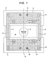
- Fig. 1 is a cross sectional view of the superconducting magnet apparatus showing an embodiment of the present invention
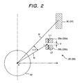
- Fig. 2 is a view explaining the relationship between the divided main coils and counteracting coils
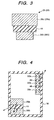
- Fig. 3 is a cross sectional view when a support member is inserted between the divided main coils
- Fig. 4 is a cross sectional view when the main coils and the counteracting coils are divided into plural pieces
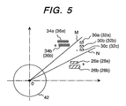
- Fig. 5 is a view explaining position relationship when the main coils, counteracting coils and correction coils are divided into plural pieces.
- FIG. 1 is a cross sectional view of the superconducting magnet apparatus showing an embodiment of the present invention.
- a superconducting magnet apparatus of vertical magnetic field type has a pair of vacuum chambers 10 and 12 and is used as a magnetic field generation source for the magnetic resonance imaging apparatus.
- the vacuum chambers are formed cylindrically and positioned separately at upper and lower portions.
- the upper vacuum chamber 10 and lower vacuum chamber 12 are connected each other through supports 14 and 16.
- a cylindrical cooling medium chambers 18 and 20 are accommodated in the vacuum chamber 10 and 12, and pipes 22 and 24 forming cooling paths are inserted into the supports 14 and 16.
- the cooling medium chambers 18 and 20 opposing each other are accommodated in the vacuum chambers 10 and 12 so as to suppress heat convection.
- the magnet field space(measuring space) is formed between the vacuum chambers 10 and 12.
- Main coils 26, 28, counteracting coil 30,32, correction coils 34,36 are enclosed together with superconducting cooling medium(not shown) in the cooling medium chambers 18 and 20. These coils have different diameter and act as supercondunting coils.
- superconducting coil material for example, wiring material made of NbTi is used, and as superconducting cooling medium, for example, liquid helium is used.
- the cooling medium is cooled, for example, by a refrigerator(not shown).
- the main coils 26, 28 counteracting coils 30, 32 and correction coils 34, 36 are annularly formed and arranged concentric with respect to the center of an axis 40.
- the main coil 26 and 28 form a spherical imaging region 42 in the partial region of the magnetic field space 38.
- the imaging region 42 is an uniform magnetic field.
- the main coils 26 and 28 form highest intensity magnetic field in the plurality of supercoducting coils and uniform and vertical magnetic field(static magnetic field) more than predetermined level in the magnetic field region 38.
- the counteracting coils 30 and 32 are arranged in adjacent to the main coils 26 and 28 with largest diameter in the plurality of superconducting coils.
- the direction of the current flowing through the counteracting coils 30 and 32 is opposed to that of the main coils 26 and 28.
- the correction coils 34 and 36 are arranged adjacent to the counteracting coils 30 and 32.
- the correction coils 34 and 36 correct un-uniform component of the magnetic field in the imaging region 42 in the magnetic field formed by the main coils 26, 28 and counteracting coils 30, 32, and keep the imaging region 42 uniform magnetic field region.
- the magnetomotive force of the correction coils 30 and 32 are lower than that of the main coils 26,28 and counteracting coils 30 32.
- the direction of the current of the correction coils 34 and 36 are determined by the un-uniform component of the magnetic field generated at the imaging region 42.
- a plurality of coils having different diameter are applicable as the correction coils 34 and 36.
- the current direction may be changeable to select the same direction as the main coils or reverse direction according to the un-uniform component of the imaging region 42.
- the main coils 26 and 28, counteracting coils 30 , 32 and correction coils are supported by a support member(not shown) respectively, and the support member is fixed to the cooling chambers 18, 20.
- each main coils 26,28 is divided into two main coils 26a, 26b and 28a,28b respectively as shown in Fig. 2.
- the distance d between the divided main coil 26a and 26b and the distance d between the main coil 28a and 28bare determined by the following formula (1).
- L1 is length of the main coils in the sectional plane(short side length of rectangular)
- L2 is length of the main coils 26a, 26b in the sectional plane(short side length of rectangular)
- r is distance between the center O of imaging region 42 and the center of the main coils 26, 28( distance in the apace between the center of the main coils 26a, 28b and that of the main coils 26b, 28b)
- ⁇ is an angle which a strait line M connecting the center O of the imaging region 42 and center of counteracting coil 30 or 32, and a strait line N connecting the center O and center of the main coil 26 and 28 make.
- a support member 44 using insulating material is inserted between the divided main coils 26a, 26b and the main coils 26b, 28b as shown in Fig. 3 and each main coils 26a, 26b, 28a, 28b is supported by the cooling chamber 18 and 20 through the support member 44 or the support.
- the main coils 26, 28 in the plurality of superconducting coils are separated into two portions. Therefore, it is capable of reducing the current density in comparison with a single unit coil. As a result, the maximum experience magnetic field of the main coils 26a, 26b, 28a, 28b may be reduced. Further, the compression stress of the main coils 26, 28 may be reduced by dispersing the electromagnetic force generated by each main coils 26a, 26b, 28a, 28b.
- the reduction of the maximum experience magnetic field of the main coils 26a,26b,28a,28b results in increase of maximum allowable current of the main coils 26a,26b,28a,28b in comparison with the main coils 26, 28 structured by a single unit coil. Therefore, it is capable of using cheaper wire as material of main coils 26a,26b,28a,28b and reducing the cost in generating same magnetomotive force.
- the compression stress may be reduced. Accordingly, it is able to use thinner support using in comparison with the main coils 26,28 of single unit coil, and the cost down is carried out by reducing the support material. On the other hand, if the same thick support is used, the support intensity is improved.
- the main coils 26a and 28a may be brought close each other and uniformity of magnetic field of the imaging region 42 is considerably improved.
- the main coils 26 and 28 are divided into two pieces, and the counteracting coils 30 and 32 may be divided into three pieces as shown in Fig. 4.
- a support member 46 is inserted between the divided counteracting coils 30a and 30b, and a support member 48 is inserted between the divided counteracting coils 30b and 30c in the counteracting coils 30a, 30b, 30c or 32a, 32b, 32c.
- the support member 46 and 48 are united with a support 50 formed of box type same as support member 44 inserted between the main coils 26a and 26b,or between the main coils 28a and 28b. That is, the divided counteracting coils 30a,30b, 30c or 32a, 32b, 32c are supported by the support member 46 and 48 or the support 50
- the counteracting coils 30, 32 are divided into three pieces and the electromagnetic force by each counteracting coils 30a, 30b, 30c or 32a, 32b, 32c is dispersed. Therefore, it is able to reduce the compression stress and the thickness of the support 50 in comparison with the single united coil.
- the main coils 26,28, counteracting coils 30,32 are divided into plural pieces. It is possible to divide the correction coils 34,36 into plural pieces and insert support members between the divided correction coil. The divided correction coils are supported by the support member or support. In this case, it is possible to thin the thickness of the support and use cheaper wiring material according to the reduction of the maximum experience magnetic field.
- main coils 26 and 28 are divided into two pieces, it is possible to insert a ferromagnetic substance, for example, iron member inside the main coils 26b,28b of the imaging region 42.
- a ferromagnetic substance for example, iron member
- counteracting coils 30a,32b,30b,32b,30c and 32c are arranged in the region between the strait lines M and N as shown in Fig. 5
- the main coils 26a, 28a, 26b, and 28b are arranged in the lower region and the correction coils 34a, 36b,34b and 36b are arranged in the upper region outside the region surrounded by the strait lines M and N, respectively.
- the current direction of the main coils 26 and 28 is set as positive
- the current direction of the counteracting coils 30 and 32 is set as negative
- the current direction of the correction coils 34 and 36 is set as positive.
Landscapes
- Physics & Mathematics (AREA)
- Condensed Matter Physics & Semiconductors (AREA)
- General Physics & Mathematics (AREA)
- Magnetic Resonance Imaging Apparatus (AREA)
Applications Claiming Priority (2)
| Application Number | Priority Date | Filing Date | Title |
|---|---|---|---|
| JP2003340210A JP3624254B1 (ja) | 2003-09-30 | 2003-09-30 | 超伝導磁石装置 |
| JP2003340210 | 2003-09-30 |
Publications (2)
| Publication Number | Publication Date |
|---|---|
| EP1521095A1 true EP1521095A1 (fr) | 2005-04-06 |
| EP1521095B1 EP1521095B1 (fr) | 2010-03-17 |
Family
ID=34309038
Family Applications (1)
| Application Number | Title | Priority Date | Filing Date |
|---|---|---|---|
| EP04256057A Expired - Lifetime EP1521095B1 (fr) | 2003-09-30 | 2004-09-30 | Aimant superconducteur |
Country Status (4)
| Country | Link |
|---|---|
| US (1) | US8134433B2 (fr) |
| EP (1) | EP1521095B1 (fr) |
| JP (1) | JP3624254B1 (fr) |
| DE (1) | DE602004026017D1 (fr) |
Families Citing this family (3)
| Publication number | Priority date | Publication date | Assignee | Title |
|---|---|---|---|---|
| US9513353B2 (en) * | 2008-05-08 | 2016-12-06 | The University Of Queensland | Arrangement of coils for MRI apparatus |
| US8253416B2 (en) * | 2009-03-10 | 2012-08-28 | Time Medical Holdings Company Limited | Superconductor magnetic resonance imaging system and method (super-MRI) |
| JP6328487B2 (ja) * | 2014-05-20 | 2018-05-23 | 住友重機械工業株式会社 | 超伝導電磁石及び荷電粒子線治療装置 |
Citations (4)
| Publication number | Priority date | Publication date | Assignee | Title |
|---|---|---|---|---|
| EP0807940A1 (fr) * | 1995-11-30 | 1997-11-19 | Hitachi Medical Corporation | Dispositif a aimant supraconducteur |
| JPH1099296A (ja) * | 1996-08-07 | 1998-04-21 | Mitsubishi Electric Corp | 分割型mri用磁場発生装置 |
| WO2002027346A1 (fr) * | 2000-09-26 | 2002-04-04 | Koninklijke Philips Electronics N.V. | Appareil d'irm à champ vertical pourvu d'une bobine de gradient conique située dans l'aimant principal |
| WO2002065149A1 (fr) * | 2001-02-02 | 2002-08-22 | Oxford Magnet Technology Limited | Aimant d'irm superconducteur ouvert a champ magnetique transversal |
Family Cites Families (10)
| Publication number | Priority date | Publication date | Assignee | Title |
|---|---|---|---|---|
| JPH06132120A (ja) | 1992-10-19 | 1994-05-13 | Mitsubishi Electric Corp | 超電導マグネット装置 |
| DE4416907C1 (de) * | 1994-05-13 | 1995-09-07 | Bruker Analytische Messtechnik | Therapietomograph mit Homogenisierungseinrichtung |
| GB2309305B (en) * | 1996-01-19 | 2000-05-31 | Oxford Magnet Tech | Improvements in or relating to MRI magnets |
| JP2002034947A (ja) | 1997-10-24 | 2002-02-05 | Hitachi Ltd | マグネット装置、および、これを用いたmri装置 |
| US6011454A (en) * | 1998-12-30 | 2000-01-04 | Huang; Xianrui | Superconducting magnet suspension assembly |
| JP2002017709A (ja) | 2000-07-11 | 2002-01-22 | Hitachi Medical Corp | 磁気共鳴イメージング装置 |
| US6570475B1 (en) * | 2000-11-20 | 2003-05-27 | Intermagnetics General Corp. | Split type magnetic resonance imaging magnet |
| US6909348B2 (en) * | 2000-12-05 | 2005-06-21 | Hitachi, Ltd. | Low-leakage magnetic-field magnet and shield coil assembly |
| JP2002336215A (ja) | 2001-05-17 | 2002-11-26 | Mitsubishi Electric Corp | 超電導マグネット装置及び磁場均一度調整方法 |
| DE60230561D1 (de) * | 2001-05-17 | 2009-02-12 | Mitsubishi Electric Corp | Supraleitender Magnet für die bildgebende magnetische Resonanz |
-
2003
- 2003-09-30 JP JP2003340210A patent/JP3624254B1/ja not_active Expired - Fee Related
-
2004
- 2004-09-28 US US10/950,392 patent/US8134433B2/en not_active Expired - Fee Related
- 2004-09-30 DE DE602004026017T patent/DE602004026017D1/de not_active Expired - Lifetime
- 2004-09-30 EP EP04256057A patent/EP1521095B1/fr not_active Expired - Lifetime
Patent Citations (5)
| Publication number | Priority date | Publication date | Assignee | Title |
|---|---|---|---|---|
| EP0807940A1 (fr) * | 1995-11-30 | 1997-11-19 | Hitachi Medical Corporation | Dispositif a aimant supraconducteur |
| US6580346B1 (en) * | 1995-11-30 | 2003-06-17 | Hitachi Medical Corporation | Magnetic resonance imaging apparatus |
| JPH1099296A (ja) * | 1996-08-07 | 1998-04-21 | Mitsubishi Electric Corp | 分割型mri用磁場発生装置 |
| WO2002027346A1 (fr) * | 2000-09-26 | 2002-04-04 | Koninklijke Philips Electronics N.V. | Appareil d'irm à champ vertical pourvu d'une bobine de gradient conique située dans l'aimant principal |
| WO2002065149A1 (fr) * | 2001-02-02 | 2002-08-22 | Oxford Magnet Technology Limited | Aimant d'irm superconducteur ouvert a champ magnetique transversal |
Non-Patent Citations (1)
| Title |
|---|
| PATENT ABSTRACTS OF JAPAN vol. 1998, no. 09 31 July 1998 (1998-07-31) * |
Also Published As
| Publication number | Publication date |
|---|---|
| US20050068139A1 (en) | 2005-03-31 |
| DE602004026017D1 (de) | 2010-04-29 |
| US8134433B2 (en) | 2012-03-13 |
| JP3624254B1 (ja) | 2005-03-02 |
| EP1521095B1 (fr) | 2010-03-17 |
| JP2005102951A (ja) | 2005-04-21 |
Similar Documents
| Publication | Publication Date | Title |
|---|---|---|
| US5565831A (en) | Shielded and open MRI magnet | |
| EP0216404B1 (fr) | Appareil pour l'imagerie par résonance magnétique comportant des éléments magnétiques d'homogénéisation | |
| EP0304126B1 (fr) | Appareil à résonanse magnétique comportant un système de bobines à gradient | |
| EP0807940A1 (fr) | Dispositif a aimant supraconducteur | |
| US7193416B2 (en) | Open magnetic resonance imaging (MRI) magnet system | |
| US7928730B2 (en) | Electromagnet apparatus generating a homogeneous magnetic field with ferromagnetic members arranged inside cryogenic vessels | |
| CN101894652A (zh) | 超导磁体 | |
| EP1226448B1 (fr) | Systeme d'imagerie par resonance magnetique permettant un acces plus facile | |
| US4728895A (en) | System of coils for producing additional fields for obtaining polarization fields with constant gradients in a magnet having polarization pole pieces for image production by nuclear magnetic resonance | |
| US6965236B2 (en) | MRI system utilizing supplemental static field-shaping coils | |
| US5942898A (en) | Thrust balanced bi-planar gradient set for MRI scanners | |
| US6856223B1 (en) | Open-type magnet device for MRI | |
| US6825668B2 (en) | Static magnetic field generating apparatus and magnetic resonance imaging apparatus | |
| JP4191319B2 (ja) | 磁気共鳴映像システムの改良装置または該システム関連の改良装置 | |
| US9927507B2 (en) | Gradient magnetic field coil device and magnetic resonance imaging device | |
| JP2009172085A (ja) | 超電導磁石装置、およびこれを用いた磁気共鳴イメージング装置、並びに核磁気共鳴装置 | |
| EP1521095A1 (fr) | Aimant superconducteur | |
| US7230426B2 (en) | Split-shield gradient coil with improved fringe-field | |
| US8698499B2 (en) | Electromagnet devices compatible with magnetic resonance and MRI devices where circulating current directions alternate between coil groups separated by elevation angles between 26.25 and 55 degrees | |
| US6937017B2 (en) | Magnetic pole magnet device using the magnetic pole, and magnetic resonance imaging apparatus | |
| US20050122106A1 (en) | Gradient coil arrangement | |
| US10859649B2 (en) | Vibration reduction for a magnetic resonance imaging apparatus | |
| EP0826978A1 (fr) | Aimant fermé pour l'imagerie par résonance magnétique de forme compacte | |
| JP4392978B2 (ja) | 傾斜磁場コイル及びそれを用いた磁気共鳴イメージング装置 | |
| US20230314537A1 (en) | Receiving coil and mri apparatus |
Legal Events
| Date | Code | Title | Description |
|---|---|---|---|
| PUAI | Public reference made under article 153(3) epc to a published international application that has entered the european phase |
Free format text: ORIGINAL CODE: 0009012 |
|
| 17P | Request for examination filed |
Effective date: 20041019 |
|
| AK | Designated contracting states |
Kind code of ref document: A1 Designated state(s): AT BE BG CH CY CZ DE DK EE ES FI FR GB GR HU IE IT LI LU MC NL PL PT RO SE SI SK TR |
|
| AX | Request for extension of the european patent |
Extension state: AL HR LT LV MK |
|
| AKX | Designation fees paid |
Designated state(s): DE FR GB IT |
|
| GRAP | Despatch of communication of intention to grant a patent |
Free format text: ORIGINAL CODE: EPIDOSNIGR1 |
|
| GRAS | Grant fee paid |
Free format text: ORIGINAL CODE: EPIDOSNIGR3 |
|
| GRAA | (expected) grant |
Free format text: ORIGINAL CODE: 0009210 |
|
| AK | Designated contracting states |
Kind code of ref document: B1 Designated state(s): DE FR GB IT |
|
| REG | Reference to a national code |
Ref country code: GB Ref legal event code: FG4D |
|
| REF | Corresponds to: |
Ref document number: 602004026017 Country of ref document: DE Date of ref document: 20100429 Kind code of ref document: P |
|
| PGFP | Annual fee paid to national office [announced via postgrant information from national office to epo] |
Ref country code: FR Payment date: 20100910 Year of fee payment: 7 |
|
| PGFP | Annual fee paid to national office [announced via postgrant information from national office to epo] |
Ref country code: GB Payment date: 20100819 Year of fee payment: 7 |
|
| PLBE | No opposition filed within time limit |
Free format text: ORIGINAL CODE: 0009261 |
|
| STAA | Information on the status of an ep patent application or granted ep patent |
Free format text: STATUS: NO OPPOSITION FILED WITHIN TIME LIMIT |
|
| 26N | No opposition filed |
Effective date: 20101220 |
|
| PGFP | Annual fee paid to national office [announced via postgrant information from national office to epo] |
Ref country code: DE Payment date: 20101125 Year of fee payment: 7 |
|
| PGFP | Annual fee paid to national office [announced via postgrant information from national office to epo] |
Ref country code: IT Payment date: 20100928 Year of fee payment: 7 |
|
| GBPC | Gb: european patent ceased through non-payment of renewal fee |
Effective date: 20110930 |
|
| PG25 | Lapsed in a contracting state [announced via postgrant information from national office to epo] |
Ref country code: IT Free format text: LAPSE BECAUSE OF NON-PAYMENT OF DUE FEES Effective date: 20110930 |
|
| REG | Reference to a national code |
Ref country code: FR Ref legal event code: ST Effective date: 20120531 |
|
| PG25 | Lapsed in a contracting state [announced via postgrant information from national office to epo] |
Ref country code: DE Free format text: LAPSE BECAUSE OF NON-PAYMENT OF DUE FEES Effective date: 20120403 |
|
| REG | Reference to a national code |
Ref country code: DE Ref legal event code: R119 Ref document number: 602004026017 Country of ref document: DE Effective date: 20120403 |
|
| PG25 | Lapsed in a contracting state [announced via postgrant information from national office to epo] |
Ref country code: GB Free format text: LAPSE BECAUSE OF NON-PAYMENT OF DUE FEES Effective date: 20110930 Ref country code: FR Free format text: LAPSE BECAUSE OF NON-PAYMENT OF DUE FEES Effective date: 20110930 |