EP1521101A1 - Detecteur d'objets non autorisés dans une zone à accès protégé - Google Patents
Detecteur d'objets non autorisés dans une zone à accès protégé Download PDFInfo
- Publication number
- EP1521101A1 EP1521101A1 EP04292345A EP04292345A EP1521101A1 EP 1521101 A1 EP1521101 A1 EP 1521101A1 EP 04292345 A EP04292345 A EP 04292345A EP 04292345 A EP04292345 A EP 04292345A EP 1521101 A1 EP1521101 A1 EP 1521101A1
- Authority
- EP
- European Patent Office
- Prior art keywords
- detection
- support base
- shoe
- order
- height
- Prior art date
- Legal status (The legal status is an assumption and is not a legal conclusion. Google has not performed a legal analysis and makes no representation as to the accuracy of the status listed.)
- Granted
Links
Images


Classifications
-
- G—PHYSICS
- G01—MEASURING; TESTING
- G01V—GEOPHYSICS; GRAVITATIONAL MEASUREMENTS; DETECTING MASSES OR OBJECTS; TAGS
- G01V9/00—Prospecting or detecting by methods not provided for in groups G01V1/00 - G01V8/00
-
- G—PHYSICS
- G01—MEASURING; TESTING
- G01V—GEOPHYSICS; GRAVITATIONAL MEASUREMENTS; DETECTING MASSES OR OBJECTS; TAGS
- G01V3/00—Electric or magnetic prospecting or detecting; Measuring magnetic field characteristics of the earth, e.g. declination, deviation
- G01V3/08—Electric or magnetic prospecting or detecting; Measuring magnetic field characteristics of the earth, e.g. declination, deviation operating with magnetic or electric fields produced or modified by objects or geological structures or by detecting devices
Definitions
- the present invention relates to the field of detectors designed to detect unauthorized objects in an access area protected.
- the present invention applies in particular to the detection of metal objects.
- the problem thus posed covers a very wide range of situations which include, but are not limited to, the detection of theft of objects in shops, businesses or warehouses where the attempt to introduce dangerous objects into a protected area, such as a shop, a school, a train station, a public body see private.
- detectors including metal detectors in the documents FR-2720519, FR-2775350, FR-2780585, FR-2694098, FR-2697919, FR-2698178, FR-2698968, FR-2608286, FR-2610417, FR-2607937, FR-2608286, FR-2607937, US-6362739, US-6359582, US-6344818, US-6342696, US-6218830, US-5790685, US-5680103, US-5341126, WO03 / 032011, US-20010042412, WO98 / 12573, WO97 / 50000, WO97 / 42527, EP-0740822, EP-0490921, WO91 / 03746, US-5121105, WO88 / 07733, US-20030142853, US-20030128150, U.S.-6507309, US-6507278, US-20020130804, US
- This phenomenon seems mainly due to the fact that this area of the human body is difficult to control easily visually or by manual probing.
- the present invention therefore aims to propose new ways to improve the reliability of detection of objects in a protected access area.
- the invention is distinguished prior devices known from the aforementioned literature and / or of previous uses, in that the device is designed to operate the detection on one foot (shoe) at a time, and therefore successively on both feet (shoes).
- the inventor has indeed determined that the proposed devices in the prior art suffer from a major disadvantage: they operate the detection simultaneously on both feet. And under these conditions, the interaction between the materials of the objects carried by the two feet or shoes disturb the detection.
- the support base comprises a platform shaped step which has on its upper surface the reference means of positioning.
- These positioning reference means comprise of preferably an authorized fingerprint and frame design, combined with a mechanical stop for the heel of the shoe.
- the support base 100 has the geometry of a rectangular tray shaped walk. Its upper surface 102 is flat.
- the two vertical side panels 200 have an outline globally rectangular. They are flat and parallel to each other. The two panels 200 project upwards, above the base 100, adjacent to its lateral sides 103, 104. The two panels 200 side and form in combination with the underlying support base 100, a channel that can accommodate the foot, equipped with a shoe, of a user.
- the vertical side panels 200 preferably house coils of electrically conductive yarns intended for the detection of metals according to a method known per se.
- the height of the panels 200 and the coils housed therein is adapted to allow reliable detection of metal objects worn by an individual at the level of his shoe, but also at level of the lower leg, that is to say, calf up to the knee.
- the walk-shaped structure proposed for the base support 100 is designed in such a way that the person examined does not have to be placed on a base, with the risk of falling and psychological discomfort resulting from exposure to other persons nearby. Indeed, the use of a support base 100 designed to to receive a single foot requires only one act of the type initial act of climb on a ladder by stepping into a well-marked area.
- the means 300 preferably comprises also the processing means able to exploit the signals electrical windings from the windings housed in the side panels 200.
- the detector means placed in the side panels 200 may consist of compliant transmitter and receiver coils any appropriate arrangement known to those skilled in the art.
- the coils include, as illustrated for example in Figure 4, several inverted sense series loops to neutralize the effects of external parasites; that the device preferably includes both transmission level than the reception of offset windings between them; and that, preferably, the windings are powered by signals comprising complex harmonic components.
- They preferably include a drawing 410 combined with a stop 450.
- Drawing 410 itself preferably includes three elements in combination: a center line 420, a frame 430 and a impression 440.
- the center line 420 extends parallel to the panels lateral 200 midway away from these. It's centered on the 430 frame and of length preferably limited thereto.
- the frame 430 is preferably a rectangular frame comprising two long sides 432, 434 parallel to each other and parallel to the center line 420, as well as parallel to the panels 200 side and two short sides 436, 438 parallel to each other, perpendicular to the long sides 432, 434, and connecting them.
- the long sides 432, 434 have preferably a length identical to that of the center line 420.
- the impression 440 is preferably formed by the combination of two parts of ellipse 442, 444 whose concavities are directed, one towards each other and which intersect each other. Both parts of ellipse have different dimensions: one 442 of small extension is intended to be placed under tarsus, while the other 444 of highest extension is intended to be placed under the metatarsus.
- the two parts of ellipse 442, 444 are each symmetrical about the center line 420. outer contour of the small ellipse 444 is adjacent to the small side 436 of frame 430.
- the stop 450 may be formed of any embodiment appropriate. It is preferably a slightly curved protrusion provided at the level of the common area with short sides 436 of the frame and at the rear part of the impression 440, to serve as a support for the heel of the shoe.
- the positioning imprint 400 can be drawn or engraved on the upper plane 102 of the step 100.
- the stop 450 forms a reference shoe, in relief, which makes it possible to impose the position of the heel of the shoe and thus allows a precise repetitive positioning of the shoe compared to the windings embedded in the panels 200.
- the inventor has indeed determined that such positioning accurate repetition is essential for reliable analysis with rejection maximum of the metal parts which normally constitute the shoes (shank or heel).
- such vertical panels 200 extend antennas at a height to ensure useful and uniform signal even if the objects to detect, weapons or objects forbidden similar, of minimum signal, are positioned at the height of the ankle or above the ankle.
- windings configured in a horizontal plane in accordance with certain provisions of the state of the art, for example in the support plan of a platform, do not offer such a possibility, because the sensibility interception is greatly reduced with the distance of the windings.
- the panels vertical positions are positioned at a reduced reciprocal distance (preferably between 450 and 700 mm, typically of the order of 575 mm) set to obtain, simultaneously, a good detection signal objects sought and a certain tolerance in relation to transverse positioning variations of the examined shoe.
- the windings for generating and receiving the electromagnetic field are positioned so that the magnetic field of detection is modeled in an optimal way with respect to the areas of the shoes that usually have the largest amount of metal. More more precisely, preferably, the coils are thus positioned depending on the positioning zone of the reinforcement blade horizontal metal or "shank" conventionally provided in the sole of a shoe.
- FIG. 4 under the reference 500, shows the curve of sensitivity of the receiver windings 250 and transmitter 260 schematized in figure 4. It will be noted that as indicated previously the field magnetic detection is conveniently modeled in 502 on the position of the metal element referenced 1 reinforcement provided in the sole of the shoe and generally referred to as "shank".
- the magnetic field of detection is conveniently modeled at a distance between 10 and 20 cm from the abutment 450, typically at a distance of distance of about 15mm from this stop.
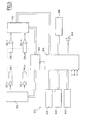
- FIG. 6 shows a central unit 602, which includes the program storage means necessary and the appropriate means of treatment to manage all interfaces and exploit the signals collected.
- these display means 612 are materialized by two display bars arranged on the vertical edge before 200 side panels as seen in Figure 1.
- Each of these 612 is split into a plurality of display devices punctual, selectively powered, when detecting an object determined, at the height of detection.
- the central unit 602 shown in the attached FIG. also in communication with a time base 620 which control, on the one hand the power supply of the transmitter coils, and on the other hand in synchronism the detection of signals from windings receptors.
- 260.1 was thus represented, 260.n, independent transmitter windings powered respectively by pilot circuits 261.1, 261.n, which are themselves connected to an excitation signal generator 262 driven by the timebase 120.
- the circuit 252 is clocked by the time base 620 and connected to the unit Central 602.
- the number of transmitting coils 260 and the number of receiver windings 250 is not limited to two. By elsewhere, the number of transmitting coils 260 is not necessarily identical to the number of receiver coils 250.
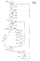
- FIG. the general flow chart of such a device.
- step 700 is an initialization step.
- Step 702 is a step of displaying a signal, by example "READY" indicating that the device is ready for a measurement.
- CPU 602 examines, by any processing appropriate (the exploitation of the signals from the windings or the signal from an auxiliary detector, for example a detector optical) if a shoe is present in the detection field.
- step 702 is repeated.
- step 704 is followed by step 706 during which the central unit 602 imposes on the device display 610 viewing information inviting the individual controlled to place his shoe on the footprint 400, for example using signal "PLACE SHOE".
- the subsequent step 708 is a delay step leaving to the individual the time to correctly place the shoe on the footprint 400 or remove the shoe, following a previous check.
- the CPU examines whether a shoe is correctly positioned on the footprint 400.
- step 710 is followed by a step 730 of resetting the device and viewing a signal in accordingly on the display 610, for example "RESET".
- step 710 is followed by a step 712 during which the central unit 602 operates the analysis properly said signals from the receiver windings 250.
- the central unit 602 proceeds with the course of a step 714 to the analysis of the result of the signal processing for determine whether or not it should lead to an alarm.
- step 714 is followed by a step 716 at during which an audible signal is emitted on the means 604 and / or a appropriate visual signal is emitted on the display 610.
- step 714 is followed by a step 718 indicating to the controlled individual and to the control personnel that no fraudulent object was detected, for example in the form of the signal "PASSED".
- This visualization step 718 is followed by a step of timeout 720, then a step 722 during which the unit 602 controls the display on the display 610 of a message inviting the controlled individual to remove his shoe, for example under signal form "REMOVE".
- Steps 716 and 722 are followed by a delay step 724 to enable the controlled individual to properly remove his shoe.
- Step 724 is followed by the aforementioned step 730.
- step 732 is itself followed by a step of timing 732 to allow a stabilization of the signal. Then step 732 is looped upstream of the visualization step 702 supra.
- the device according to the present invention comprises random sorting means for random assignment of individuals to one or more complementary tests.
- the additional test (s) may for example, a manual probing or a device automatic analysis, for example sampling and analysis of vapor or trace particles, for example narcotics or explosive.
- FIG. 8 The flowchart of operation of such a device comprising a random sorting designation is illustrated in FIG. 8.
- step 714 In case of alarm detection in step 714, this is always followed by the visualization step 716.
- step 714 random selection calculation.
- the central unit 602 determines whether or not the individual in Control course was thus randomly selected. In in the affirmative, step 742 is followed by the visualization step 716. the negative step 742 is followed by the visualization step leading to an authorization 718.
- the device complies with the The present invention may be supplemented by suction means of vapor and / or traces of sensitive matter, for example astonishing explosive possibly from shoes.
- suction means are preferably integrated in the side panels 200 and in the support base 100 forming a step.
- FIG. 3 a variant embodiment of the device according to which the side panels 200 and the base support 100 comprise a plurality of suction nozzles 800.
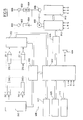
- FIG. 9 is a diagrammatic representation of the structure of a complete device according to the present invention integrating such sampling means and the processing means associates.
- the nozzles 800 are followed by 802 filters and 804 flow control means. last are themselves connected to the input of a pump 806 actuated by a motor 808.
- the output of the pump 806 is connected to a detector 810, for example of the mass spectrometer type.
- the detector 810 and the motor 808 are connected and controlled by a 812, itself connected, for example by the interface 606 and any means appropriate to the General Central Unit 602.
- Step 750 which follows step 714 in case of non-detection of a metal object corresponds to the vapor sampling and analysis step and / or traces of wanted materials, for example narcotics.
- step 752 is a test step. In case of detection of such a substance it is followed by the aforementioned alarm display step 716. On the contrary in case of no detection of prohibited substance, the test step 752 is followed by the step of displaying an authorization signal in step 718.
- the aforementioned 810 analysis system can be placed anywhere appropriate device, preferably inside the base plate 100.
- the nozzles 800 can be replaced directly by specialized monolithic sensors, electrically connected to the processing unit 812.
- the stop 450 for the heel can to be omitted.
Landscapes
- Physics & Mathematics (AREA)
- Life Sciences & Earth Sciences (AREA)
- General Life Sciences & Earth Sciences (AREA)
- General Physics & Mathematics (AREA)
- Geophysics (AREA)
- Engineering & Computer Science (AREA)
- Remote Sensing (AREA)
- Electromagnetism (AREA)
- Environmental & Geological Engineering (AREA)
- Geology (AREA)
- Geophysics And Detection Of Objects (AREA)
- Footwear And Its Accessory, Manufacturing Method And Apparatuses (AREA)
Abstract
Description
- une embase support conçue pour recevoir un pied unique, revêtu de sa chaussure, d'un individu à contrôler,
- des moyens détecteurs adaptés pour la détection d'un matériau cible, liés à l'embase support, et
- des moyens repères de positionnement, sur l'embase support, aptes à imposer un positionnement précis du pied de l'individu à contrôler par rapport aux moyens détecteurs.
- le dispositif comporte un moyen qui délivre des messages visuels ou sonores guidant l'utilisateur au cours des étapes successives de la détection (mise en place, détection proprement dite, retrait et réitération pour le second pied),
- le dispositif comporte des moyens de tri aléatoire pour la désignation aléatoire d'individus dirigés vers un ou plusieurs test(s) complémentaire(s),
- le dispositif comporte des moyens de prélèvement de vapeurs ou traces de particules, par exemple de stupéfiants ou explosifs, et d'analyse de ces vapeurs ou traces.
- la figure 1 représente une vue schématique en perspective du bâti d'un dispositif conforme à la présente invention,
- la figure 2 représente une vue en plan d'un mode de réalisation préférentiel de moyens repères de positionnement proposés dans le cadre de la présente invention,
- la figure 3 représente une vue en perspective d'une variante de réalisation d'un bâti conforme à la présente invention équipé de moyens de détection de vapeur ou de trace de particules,
- la figure 4 représente schématiquement le positionnement d'une chaussure par rapport à des bobinages de détection,
- la figure 5 représente sous forme de blocs fonctionnels le synoptique de fonctionnement d'un dispositif conforme à un mode de réalisation préférentiel de la présente invention,
- la figure 6 représente l'organigramme de fonctionnement de ce dispositif,
- la figure 7 représente un organigramme conforme à une variante de réalisation de la présente invention comportant une étape de tri aléatoire d'individus dirigés vers un ou plusieurs tests complémentaires,
- la figure 8 représente le synoptique, sous forme de blocs fonctionnels, d'un dispositif conforme à une variante de la présente invention comprenant des moyens de prélèvement et d'analyse de vapeur ou trace de particules de matériau, et
- la figure 9 représente un organigramme de fonctionnement de ce dispositif.
- une embase support 100,
- deux panneaux latéraux symétriques 200, et
- un module d'informations 300.
- largeur comprise entre 450 et 700mm, typiquement de l'ordre de 575mm,
- profondeur comprise entre 500 et 900mm, typiquement de l'ordre de 670mm, et
- hauteur comprise entre 100 et 200mm, typiquement de l'ordre de 150mm.
- largeur correspondant à la profondeur de l'embase support 100,
- hauteur comprise entre 300 et 900mm, typiquement de l'ordre de 690mm.
- la préparation à monter une marche est un acte quotidien normal qui ne demande pas d'instruction particulière pour sa correcte exécution,
- cette même opération ne demande pas d'effort physique, même de la part d'une personne âgée ou d'une femme enceinte et en particulier, ne requiert pas un effort physique important, comme celui exigé par exemple pour monter une estrade,
- la structure en forme de marche permet d'éloigner du sol les antennes de génération et de réception de champs électromagnétiques constituées par les bobinages intégrés dans les panneaux latéraux 200, en réduisant ainsi les risques d'accouplement avec d'éventuelles structures métalliques intégrées dans ce sol,
- une telle structure permet de prévoir en mode naturel l'examen d'une seule chaussure à la fois, et
- permet une structure compacte par rapport à une estrade sur laquelle doit monter une personne complète, selon certains dispositifs connus de l'art antérieur.
- de signaler que le dispositif est prêt pour la détection, par exemple le message "READY",
- d'inviter l'individu à placer son pied, sa chaussure, sur l'empreinte définie à cet effet, laquelle sera décrite plus en détail par la suite, par exemple sous forme du message "PLACE SHOE",
- de signaler à l'individu que la détection a été réalisée avec succès sans détection d'alarme et l'inviter, soit à réitérer avec la seconde chaussure, soit à se retirer, par exemple sous forme des messages "PASSED" ou "REMOVE".
- largeur (soit longueur des petits côtés 436, 438) comprise entre 110 et 250mm, typiquement de l'ordre de 180mm,
- longueur (soit longueur des grands côtés 432, 434) de préférence comprise entre 300 et 500mm, typiquement de l'ordre de 400mm.
- longueur ou encombrement maximale parallèlement à la ligne médiane 420 comprise entre 250 et 350mm, typiquement de l'ordre de 300mm, et
- encombrement en largeur, soit parallèlement aux petits côtés 436, 438, du cadre compris entre 100 et 180mm, typiquement de l'ordre de 136mm.
- un moyen 604 générateur de signal acoustique d'alarme ou de messages vocaux,
- un moyen 606 de liaison avec un module extérieur, par exemple une interface type RS232,
- un moyen 608 d'introduction de données, par exemple un clavier,
- un module 610 d'affichage de caractères alpha numériques, pour la diffusion des signaux visuels de guidage précités, et de préférence,
- un module 612 de visualisation verticale de la zone de détection d'un objet interdit.
- une sécurité de contrôle élevée et homogène,
- une grande fluidité de passage sans exiger de personnel de contrôle spécialisé,
- l'élimination des coûts de personnel spécialisé dédié dans certaines applications connues à un contrôle manuel des chaussures,
- l'argumentation du confort pour le public par l'élimination de la gêne causée par l'enlèvement / la remise des chaussures et par la perte de temps associée à une telle opération,
- l'élimination de la nécessité d'appareils à rayons X requis dans certaines applications connues pour un examen,
- le dispositif est léger et peu volumineux donc aisément déplaçable et adaptable sur tout site.
- l'analyse des chaussures n'est pas effectuée en mode différentiel, comme cela est le cas dans certains appareils connus, mais de manière absolue chaussure par chaussure. Ainsi chaque chaussure est évaluée séparément et la détection de la cible métallique la plus critique, c'est-à-dire celle de signal minimal, effectuée indépendamment de la comparaison avec l'autre. L'inventeur a déterminé que cette disposition permet, bien que la quantité complète de métal présente dans une simple chaussure, soit supérieure, dans beaucoup de cas, au poids de la cible métallique de signal minimal, de garantir la sécurité d'interception des cibles de signal minimal dans toutes les conditions de transport.
- l'analyse des chaussures ne se limite pas à la partie basse de ces dernières ou aux parties immédiatement adjacentes mais, en utilisant un champ magnétique de mesure hautement uniforme et structuré, couvre la jambe jusqu'à la hauteur du mollet, sans variation de sensibilité et donc sans dégradation des prestations. Ceci garantit la sûreté également dans le cas de cibles de signal minimal transportées à la cheville ou au dessus de celle-ci.
- le système conforme à l'invention d'exploration des chaussures examinées et l'analyse associée permettent de détecter les cibles critiques, de signal minimal, en discriminant en même temps, les signaux parasites des nombreuses masses métalliques présentes dans les chaussures, même de poids supérieur à la cible à détecter. En conséquence, l'attention des opérateurs dédiés au contrôle est focalisée sur un nombre limité de cas, avec un avantage pour la sûreté.
- une influence nulle ou négligeable des structures métalliques enterrées ou présentes au niveau du sol d'appui, par exemple renforts du sol en béton armé ou lames métalliques, souvent enterrées à quelques centimètres sous la superficie du sol. Ceci grâce au désaccouplement élevé par rapport à de telles masses métalliques.
- au niveau de l'ergonomie, l'appareil est simple et confortable. Il ne contraint pas la personne examinée à avoir des comportements étranges ou à prendre des positions embarrassantes. Le temps d'analyse peut être réduit au minimum.
- l'utilisation d'une embase support en forme de marche (associée à des moyens repères de positionnement) garantit la détection sur une chaussure unique, la seconde chaussure qui repose sur le sol étant maintenue en dehors du champ de détection.
Claims (28)
- Dispositif détecteur d'objet non autorisé dans une zone à accès protégé, caractérisé par le fait qu'il comprend en combinaison :une embase support (100) conçue pour recevoir un pied unique, revêtu de sa chaussure, d'un individu à contrôler,des moyens détecteurs (250, 260, 800, 810) adaptés pour la détection d'un matériau cible, liés à l'embase support (100), etdes moyens repères (400) de positionnement, sur l'embase support (100), aptes à imposer un positionnement précis du pied de l'individu à contrôler par rapport aux moyens détecteurs.
- Dispositif selon la revendication 1, caractérisé par le fait que l'embase support (100) comporte un plateau en forme de marche qui comporte sur sa surface supérieure (102) les moyens repères de positionnement (400).
- Dispositif selon l'une des revendications 1 ou 2, caractérisé par le fait que la hauteur de l'embase support (100) est comprise entre 100 et 200mm, et très préférentiellement de l'ordre de 150mm.
- Dispositif selon l'une des revendications 1 à 3, caractérisé par le fait que la largeur de l'embase support (100) est comprise entre 450 et 700mm, et très préférentiellement de l'ordre de 575mm.
- Dispositif selon l'une des revendications 1 à 4, caractérisé par le fait que la profondeur de l'embase support (100) est comprise entre 500 et 900mm, et très préférentiellement de l'ordre de 670mm.
- Dispositif selon l'une des revendications 1 à 5, caractérisé par le fait que les moyens repères de positionnement (400) comprennent un dessin d'empreinte (410).
- Dispositif selon la revendication 6, caractérisé par le fait que le dessin d'empreinte (410) comporte un cadre, de préférence rectangulaire.
- Dispositif selon la revendication 7, caractérisé par le fait que le cadre à une longueur comprise entre 300 et 500mm, de préférence de l'ordre de 400mm et une largeur comprise entre 110 et 250mm, de préférence de l'ordre de 180mm.
- Dispositif selon l'une des revendications 6 à 8, caractérisé par le fait que le dessin d'empreinte (410) comporte une ligne médiane (420).
- Dispositif selon l'une des revendications 6 à 9, caractérisé par le fait que le dessin d'empreinte (410) comprend une empreinte (440) formée de deux ellipses (442, 444) adjacentes.
- Dispositif selon la revendication 10, caractérisé par le fait que la longueur de l'empreinte (440) est comprise entre 250 et 350mm, de préférence de l'ordre de 300mm et sa largeur comprise entre 100 et 180mm.
- Dispositif selon l'une des revendications 6 à 11, caractérisé par le fait que les moyens repères de positionnement (400) comprennent une butée mécanique (450).
- Dispositif selon la revendication 12, caractérisé par le fait que la butée mécanique (450) est adaptée pour servir de butée pour le talon d'une chaussure.
- Dispositif selon l'une des revendications 1 à 13, caractérisé par le fait que les moyens détecteurs comprennent des bobinages émetteurs et des bobinages récepteurs (250, 260) adaptés pour la détection d'objets métalliques.
- Dispositif selon l'une des revendications 1 à 14, caractérisé par le fait que le champ magnétique de détection est modelé d'une façon optimale vis à vis des zones de la chaussure présentant usuellement la plus grande quantité de métal.
- Dispositif selon l'une des revendications 14 ou 15,
caractérisé par le fait que le champ de détection des moyens détecteurs (250, 260) est opportunément modelé à une distance du talon de la chaussure comprise entre 10 et 20cm, de préférence de l'ordre de 15cm. - Dispositif selon l'une des revendications 14 à 16, caractérisé par le fait que le champ magnétique de détection des moyens détecteurs (250, 260) est opportunément modelé à une distance d'une butée mécanique (450) comprise entre 10 et 20cm, de préférence de l'ordre de 15cm.
- Dispositif selon l'une des revendications 1 à 17, caractérisé par le fait qu'il comporte un moyen (300) qui délivre des messages visuels ou sonores guidant l'utilisateur au cours des étapes successives de la détection.
- Dispositif selon l'une des revendications 1 à 18, caractérisé par le fait qu'il comporte des moyens (740) de tri aléatoire pour la désignation aléatoire d'individus dirigés vers un ou plusieurs test(s) complémentaire(s).
- Dispositif selon l'une des revendications 1 à 19, caractérisé par le fait qu'il comporte des moyens (800) de prélèvement de vapeurs ou traces de particules, par exemple de stupéfiants ou explosifs, et d'analyse de ces vapeurs ou traces.
- Dispositif selon la revendication 20, caractérisé par le fait que les moyens de prélèvement comprennent des buses d'aspiration (800) sur l'embase support (100).
- Dispositif selon l'une des revendications 1 à 21, caractérisé par le fait qu'il comprend deux panneaux verticaux (200) en saillie sur l'embase support (100) qui logent des bobinages émetteurs (260) et récepteurs (250).
- Dispositif selon la revendication 22, caractérisé par le fait que les panneaux verticaux (200) possèdent des buses d'aspiration (800) pour le prélèvement de vapeurs ou traces de particules.
- Dispositif selon l'une des revendications 22 ou 23, caractérisé par le fait que la hauteur des panneaux verticaux (200) est adaptée pour la détection d'objets jusqu'à la hauteur du genou d'un individu contrôlé.
- Dispositif selon l'une des revendications 22 à 24, caractérisé par le fait que la hauteur des panneaux verticaux (200) est comprise entre 300 et 900mm.
- Dispositif selon l'une des revendications 1 à 25, caractérisé par le fait qu'il comprend plusieurs bobinages décalés en hauteur.
- Dispositif selon l'une des revendications 1 à 26, caractérisé par le fait qu'il comprend plusieurs bobinages décalés horizontalement.
- Dispositif selon l'une des revendications 1 à 27, caractérisé par le fait que l'un au moins des panneaux verticaux comporte des moyens (612) permettant de visualiser la hauteur de détection d'un objet non autorisé.
Applications Claiming Priority (2)
| Application Number | Priority Date | Filing Date | Title |
|---|---|---|---|
| FR0311575A FR2860631B1 (fr) | 2003-10-02 | 2003-10-02 | Detecteur d'objets non autorises dans une zone a acces protege |
| FR0311575 | 2003-10-02 |
Publications (2)
| Publication Number | Publication Date |
|---|---|
| EP1521101A1 true EP1521101A1 (fr) | 2005-04-06 |
| EP1521101B1 EP1521101B1 (fr) | 2010-08-04 |
Family
ID=34307376
Family Applications (1)
| Application Number | Title | Priority Date | Filing Date |
|---|---|---|---|
| EP04292345A Expired - Lifetime EP1521101B1 (fr) | 2003-10-02 | 2004-10-01 | Detecteur d'objets non autorisés dans une zone à accès protégé |
Country Status (6)
| Country | Link |
|---|---|
| US (1) | US7098789B2 (fr) |
| EP (1) | EP1521101B1 (fr) |
| CA (1) | CA2481126C (fr) |
| DE (1) | DE602004028433D1 (fr) |
| ES (1) | ES2348614T3 (fr) |
| FR (1) | FR2860631B1 (fr) |
Cited By (2)
| Publication number | Priority date | Publication date | Assignee | Title |
|---|---|---|---|---|
| FR2911212A1 (fr) * | 2007-01-10 | 2008-07-11 | Alessandro Manneschi | Detecteur de produits non autorises dans une zone a acces protege |
| WO2008008681A3 (fr) * | 2006-07-11 | 2008-12-04 | Ge Homeland Protection Inc | Système et procédé de protection de passagers |
Families Citing this family (20)
| Publication number | Priority date | Publication date | Assignee | Title |
|---|---|---|---|---|
| US6970087B2 (en) * | 2002-07-28 | 2005-11-29 | Gil Stis | Device and method of detecting metal objects |
| US7053785B2 (en) * | 2002-12-30 | 2006-05-30 | James Edward Akins | Security prescreening device |
| FR2889338B1 (fr) * | 2005-07-26 | 2007-10-05 | Alessandro Manneschi | Detecteur d'objets non autorises dans une zone a acces protege |
| US7868758B2 (en) * | 2006-03-10 | 2011-01-11 | Morpho Detection, Inc. | Passenger screening system and method |
| US20070211922A1 (en) * | 2006-03-10 | 2007-09-13 | Crowley Christopher W | Integrated verification and screening system |
| FR2901888B1 (fr) * | 2006-05-30 | 2008-08-22 | Alessandro Manneschi | Portique detecteur de metaux comportant des moyens indicateurs perfectionnes |
| US20080018451A1 (en) * | 2006-07-11 | 2008-01-24 | Jason Benfielt Slibeck | Passenger screening system and method |
| WO2008035296A2 (fr) * | 2006-09-22 | 2008-03-27 | Koninklijke Philips Electronics N.V. | Fonctionnalité étendue de dispositifs d'identification par radiofréquence rfid |
| US7595638B2 (en) * | 2006-11-14 | 2009-09-29 | Ge Homeland Protection, Inc. | Apparatus and method for detecting metallic objects in shoes |
| CN100520383C (zh) * | 2006-12-28 | 2009-07-29 | 张恩伟 | 鞋内安全检测仪 |
| US20100212401A1 (en) * | 2009-02-25 | 2010-08-26 | Crowley Christopher W | Screening system and method |
| US8424365B2 (en) * | 2009-02-25 | 2013-04-23 | Morpho Detection, Inc. | Screening system and method for operating the same |
| US9715012B2 (en) | 2013-04-25 | 2017-07-25 | Battelle Memorial Institute | Footwear scanning systems and methods |
| EP3194041B1 (fr) * | 2014-09-16 | 2018-12-19 | 3DRudder | Dispositif de commande actionné au pied, dispositif et meuble le comprenant? son procédé de fabrication |
| FR3050283B1 (fr) | 2016-04-15 | 2018-04-20 | Alessandro Manneschi | Detecteur d'objets ou de matieres non autorisees dissimules dans une chaussure |
| FR3072467B1 (fr) * | 2017-10-13 | 2021-06-18 | Alessandro Manneschi | Inspection d'une chaussure avec une camera thermique |
| FR3072468B1 (fr) | 2017-10-13 | 2020-02-14 | Alessandro Manneschi | Dispositif et procede de detection d'objets ou matieres non autorises portes par un individu dans une zone a acces protege |
| FR3072470B1 (fr) | 2017-10-13 | 2021-05-07 | Alessandro Manneschi | Dispositif et procede d'inspection de la jambe d'un individu pour deceler le port d'objets frauduleux |
| CN108049658A (zh) * | 2017-11-30 | 2018-05-18 | 江苏高科物流科技股份有限公司 | 智能移动集成房屋及其中央处理器控制方法 |
| US11520069B2 (en) | 2020-04-20 | 2022-12-06 | Battelle Memorial Institute | Footwear scanning systems and methods |
Citations (3)
| Publication number | Priority date | Publication date | Assignee | Title |
|---|---|---|---|---|
| US5039981A (en) | 1989-10-11 | 1991-08-13 | Rodriguez Joe S | Electromagnetic security detectors |
| EP0978734A2 (fr) | 1998-08-05 | 2000-02-09 | MAIER, Hans-Jürgen | Dispositif de détection des objets métalliques |
| EP1411373A2 (fr) * | 2002-10-18 | 2004-04-21 | Firma Ing. Klaus Ebinger | Dispositif et procédé de détection d'objets metalliques |
Family Cites Families (5)
| Publication number | Priority date | Publication date | Assignee | Title |
|---|---|---|---|---|
| US4146231A (en) * | 1977-08-30 | 1979-03-27 | Merkle John W | Golf swing practice platform |
| US4866439A (en) * | 1987-03-27 | 1989-09-12 | Kraus John H | Explosives detection system for an aircraft |
| WO2002058742A1 (fr) * | 2000-12-13 | 2002-08-01 | Advanced Electron Beams, Inc. | Appareil de decontamination |
| US6819241B2 (en) * | 2001-10-10 | 2004-11-16 | Ranger Security Detectors, Inc. | System and method for scanning individuals for illicit objects |
| US6970087B2 (en) * | 2002-07-28 | 2005-11-29 | Gil Stis | Device and method of detecting metal objects |
-
2003
- 2003-10-02 FR FR0311575A patent/FR2860631B1/fr not_active Expired - Fee Related
-
2004
- 2004-01-21 US US10/762,997 patent/US7098789B2/en not_active Expired - Lifetime
- 2004-09-30 CA CA002481126A patent/CA2481126C/fr not_active Expired - Lifetime
- 2004-10-01 EP EP04292345A patent/EP1521101B1/fr not_active Expired - Lifetime
- 2004-10-01 DE DE602004028433T patent/DE602004028433D1/de not_active Expired - Lifetime
- 2004-10-01 ES ES04292345T patent/ES2348614T3/es not_active Expired - Lifetime
Patent Citations (3)
| Publication number | Priority date | Publication date | Assignee | Title |
|---|---|---|---|---|
| US5039981A (en) | 1989-10-11 | 1991-08-13 | Rodriguez Joe S | Electromagnetic security detectors |
| EP0978734A2 (fr) | 1998-08-05 | 2000-02-09 | MAIER, Hans-Jürgen | Dispositif de détection des objets métalliques |
| EP1411373A2 (fr) * | 2002-10-18 | 2004-04-21 | Firma Ing. Klaus Ebinger | Dispositif et procédé de détection d'objets metalliques |
Non-Patent Citations (3)
| Title |
|---|
| "Teen's Eagle Scout project used in O'Hare security", USA TODAY, 25 July 2003 (2003-07-25), CHICAGO, USA, XP002289377, Retrieved from the Internet <URL:http://www.usatoday.com/travel/news/2003/07/25-ord-scout.htm> [retrieved on 20040721] * |
| "Teen's Eagle Scout project used in O'Hare security", USA TODAY, 25 July 2003 (2003-07-25), Retrieved from the Internet <URL:http://www.usatoday.com/travel/news/2003/07/25-ord- scout.htm> |
| "The Magshoe Shoe Scanner", XP002289378, Retrieved from the Internet <URL:http://www.global-security-solutions.com/MagShoeScanner.htm> [retrieved on 20040721] * |
Cited By (3)
| Publication number | Priority date | Publication date | Assignee | Title |
|---|---|---|---|---|
| WO2008008681A3 (fr) * | 2006-07-11 | 2008-12-04 | Ge Homeland Protection Inc | Système et procédé de protection de passagers |
| FR2911212A1 (fr) * | 2007-01-10 | 2008-07-11 | Alessandro Manneschi | Detecteur de produits non autorises dans une zone a acces protege |
| EP1944624A1 (fr) * | 2007-01-10 | 2008-07-16 | Alessandro Manneschi | Détecteur de produits non autorisés dans une zone d'accès protégée |
Also Published As
| Publication number | Publication date |
|---|---|
| FR2860631A1 (fr) | 2005-04-08 |
| US7098789B2 (en) | 2006-08-29 |
| FR2860631B1 (fr) | 2007-06-15 |
| CA2481126C (fr) | 2009-11-17 |
| DE602004028433D1 (de) | 2010-09-16 |
| US20050116825A1 (en) | 2005-06-02 |
| CA2481126A1 (fr) | 2005-04-02 |
| EP1521101B1 (fr) | 2010-08-04 |
| ES2348614T3 (es) | 2010-12-09 |
Similar Documents
| Publication | Publication Date | Title |
|---|---|---|
| EP1521101B1 (fr) | Detecteur d'objets non autorisés dans une zone à accès protégé | |
| EP3318901B1 (fr) | Détecteur d'objets ou de matières non autorisées dissimulés dans une chaussure | |
| FR2911212A1 (fr) | Detecteur de produits non autorises dans une zone a acces protege | |
| EP1892542B1 (fr) | Portique détecteur de métaux comportant des moyens indicateurs perfectionnés | |
| EP3470890B1 (fr) | Dispositif et procédé de détection d'objets ou matières non autorisés portés par un individu dans une zone à accès protégé | |
| CA3127754A1 (fr) | Moyens detecteurs de metal perfectionnes pour localiser la presence d'objets metalliques | |
| EP3470891B1 (fr) | Inspection d'une chaussure avec une caméra thermique | |
| CA3127752A1 (fr) | Scanner corporel de securite a double champ | |
| EP1752794B1 (fr) | Detecteur d'objets non autorises dans une zone a acces protege | |
| EP3470887B1 (fr) | Dispositif et procédé d'inspection de la jambe d'un individu pour déceler le port d'objets frauduleux | |
| EP3918378B1 (fr) | Détecteur pour l'inspection de bagages | |
| EP3918379A1 (fr) | Détecteur pour bagages |
Legal Events
| Date | Code | Title | Description |
|---|---|---|---|
| PUAI | Public reference made under article 153(3) epc to a published international application that has entered the european phase |
Free format text: ORIGINAL CODE: 0009012 |
|
| AK | Designated contracting states |
Kind code of ref document: A1 Designated state(s): AT BE BG CH CY CZ DE DK EE ES FI FR GB GR HU IE IT LI LU MC NL PL PT RO SE SI SK TR |
|
| AX | Request for extension of the european patent |
Extension state: AL HR LT LV MK |
|
| 17P | Request for examination filed |
Effective date: 20050926 |
|
| AKX | Designation fees paid |
Designated state(s): DE ES FR GB IT |
|
| 17Q | First examination report despatched |
Effective date: 20070924 |
|
| GRAP | Despatch of communication of intention to grant a patent |
Free format text: ORIGINAL CODE: EPIDOSNIGR1 |
|
| GRAS | Grant fee paid |
Free format text: ORIGINAL CODE: EPIDOSNIGR3 |
|
| GRAA | (expected) grant |
Free format text: ORIGINAL CODE: 0009210 |
|
| AK | Designated contracting states |
Kind code of ref document: B1 Designated state(s): DE ES FR GB IT |
|
| REG | Reference to a national code |
Ref country code: GB Ref legal event code: FG4D Free format text: NOT ENGLISH |
|
| REF | Corresponds to: |
Ref document number: 602004028433 Country of ref document: DE Date of ref document: 20100916 Kind code of ref document: P |
|
| REG | Reference to a national code |
Ref country code: ES Ref legal event code: FG2A Effective date: 20101125 |
|
| PLBE | No opposition filed within time limit |
Free format text: ORIGINAL CODE: 0009261 |
|
| STAA | Information on the status of an ep patent application or granted ep patent |
Free format text: STATUS: NO OPPOSITION FILED WITHIN TIME LIMIT |
|
| 26N | No opposition filed |
Effective date: 20110506 |
|
| REG | Reference to a national code |
Ref country code: DE Ref legal event code: R097 Ref document number: 602004028433 Country of ref document: DE Effective date: 20110506 |
|
| REG | Reference to a national code |
Ref country code: FR Ref legal event code: PLFP Year of fee payment: 12 |
|
| REG | Reference to a national code |
Ref country code: FR Ref legal event code: PLFP Year of fee payment: 13 |
|
| REG | Reference to a national code |
Ref country code: FR Ref legal event code: PLFP Year of fee payment: 14 |
|
| REG | Reference to a national code |
Ref country code: FR Ref legal event code: PLFP Year of fee payment: 15 |
|
| PGFP | Annual fee paid to national office [announced via postgrant information from national office to epo] |
Ref country code: FR Payment date: 20230913 Year of fee payment: 20 |
|
| PGFP | Annual fee paid to national office [announced via postgrant information from national office to epo] |
Ref country code: GB Payment date: 20231019 Year of fee payment: 20 |
|
| PGFP | Annual fee paid to national office [announced via postgrant information from national office to epo] |
Ref country code: ES Payment date: 20231114 Year of fee payment: 20 |
|
| PGFP | Annual fee paid to national office [announced via postgrant information from national office to epo] |
Ref country code: DE Payment date: 20231011 Year of fee payment: 20 Ref country code: IT Payment date: 20231009 Year of fee payment: 20 |
|
| REG | Reference to a national code |
Ref country code: DE Ref legal event code: R071 Ref document number: 602004028433 Country of ref document: DE |
|
| PG25 | Lapsed in a contracting state [announced via postgrant information from national office to epo] |
Ref country code: GB Free format text: LAPSE BECAUSE OF EXPIRATION OF PROTECTION Effective date: 20240930 |
|
| REG | Reference to a national code |
Ref country code: GB Ref legal event code: PE20 Expiry date: 20240930 |
|
| REG | Reference to a national code |
Ref country code: ES Ref legal event code: FD2A Effective date: 20241025 |
|
| PG25 | Lapsed in a contracting state [announced via postgrant information from national office to epo] |
Ref country code: GB Free format text: LAPSE BECAUSE OF EXPIRATION OF PROTECTION Effective date: 20240930 |
|
| PG25 | Lapsed in a contracting state [announced via postgrant information from national office to epo] |
Ref country code: ES Free format text: LAPSE BECAUSE OF EXPIRATION OF PROTECTION Effective date: 20241002 |
|
| PG25 | Lapsed in a contracting state [announced via postgrant information from national office to epo] |
Ref country code: ES Free format text: LAPSE BECAUSE OF EXPIRATION OF PROTECTION Effective date: 20241002 |