EP1521109A1 - Atténuateur optique variable - Google Patents
Atténuateur optique variable Download PDFInfo
- Publication number
- EP1521109A1 EP1521109A1 EP04021936A EP04021936A EP1521109A1 EP 1521109 A1 EP1521109 A1 EP 1521109A1 EP 04021936 A EP04021936 A EP 04021936A EP 04021936 A EP04021936 A EP 04021936A EP 1521109 A1 EP1521109 A1 EP 1521109A1
- Authority
- EP
- European Patent Office
- Prior art keywords
- aperture
- attenuator
- laser
- diaphragms
- apertures
- Prior art date
- Legal status (The legal status is an assumption and is not a legal conclusion. Google has not performed a legal analysis and makes no representation as to the accuracy of the status listed.)
- Ceased
Links
- 230000003287 optical effect Effects 0.000 title 1
- 239000000758 substrate Substances 0.000 claims abstract description 11
- 230000005855 radiation Effects 0.000 claims description 14
- 230000005670 electromagnetic radiation Effects 0.000 claims description 6
- 230000002745 absorbent Effects 0.000 claims description 3
- 239000002250 absorbent Substances 0.000 claims description 3
- 230000005540 biological transmission Effects 0.000 abstract description 6
- WGLPBDUCMAPZCE-UHFFFAOYSA-N Trioxochromium Chemical compound O=[Cr](=O)=O WGLPBDUCMAPZCE-UHFFFAOYSA-N 0.000 abstract description 5
- 229910000423 chromium oxide Inorganic materials 0.000 abstract description 4
- 239000011248 coating agent Substances 0.000 abstract description 2
- 238000000576 coating method Methods 0.000 abstract description 2
- 239000011521 glass Substances 0.000 abstract description 2
- 239000006185 dispersion Substances 0.000 abstract 1
- 238000004519 manufacturing process Methods 0.000 description 6
- 239000000463 material Substances 0.000 description 4
- 238000010521 absorption reaction Methods 0.000 description 3
- 239000004065 semiconductor Substances 0.000 description 2
- 230000003313 weakening effect Effects 0.000 description 2
- 239000011358 absorbing material Substances 0.000 description 1
- 230000002238 attenuated effect Effects 0.000 description 1
- 238000011161 development Methods 0.000 description 1
- 230000018109 developmental process Effects 0.000 description 1
- 238000006073 displacement reaction Methods 0.000 description 1
- 238000009826 distribution Methods 0.000 description 1
- 238000005286 illumination Methods 0.000 description 1
- 230000000116 mitigating effect Effects 0.000 description 1
Images
Classifications
-
- G—PHYSICS
- G02—OPTICS
- G02B—OPTICAL ELEMENTS, SYSTEMS OR APPARATUS
- G02B26/00—Optical devices or arrangements for the control of light using movable or deformable optical elements
- G02B26/02—Optical devices or arrangements for the control of light using movable or deformable optical elements for controlling the intensity of light
Definitions
- the invention relates to a variable attenuator for an electromagnetic radiation beam.
- Electromagnetic beam, in particular light radiation can, for example, with a Grauverlaufsfilter, in which a absorption layer with a variable thickness on a Substrate is applied, thereby variably attenuated, that the Grauverlaufsfilter in Beam path is shifted, so that the transmission is changed.
- Difficult is one Gray gradient filter reproducible manufacturability and durability at shorter Wavelengths. In particular, even at wavelengths of less than 200 nm are missing suitable absorption layers, so that for these wavelengths of the gray-gradient filter not more usable.
- dielectric edge filters are known in which the light, the Preferably monochromatic is to ensure good variable attenuation by one or more dielectric layers is sent whose transmission through the Angle of incidence of the light on the layer is varied.
- the disadvantage is in the dielectric Edge filter that the transmitted light depending on the currently set Incident angle is polarized differently, which is often undesirable.
- variable attenuator which is easy to handle and easy to manufacture and especially for an electromagnetic radiation having a wavelength of less than 300 nm is suitable.
- the object is achieved by a variable attenuator for a electromagnetic radiation beam that propagates along a beam path, wherein the attenuator in the beam path two, seen in the propagation direction of the beam, having successively arranged multi-aperture diaphragms, which are movable relative to each other.
- a multi-aperture diaphragm is understood here to mean any diaphragm that has several Apertures included. Apertures are areas of the aperture, where the Transmission for the electromagnetic beam is greater than in the other Areas of the aperture.
- the relative By the provision of two successive multi-aperture diaphragms, the relative can be moved to each other, the effective transmission area for the beam be changed by the relative movement of the aperture.
- the weakening can thus by Setting a geometric factor (the relative position of the two multi-aperture diaphragms) respectively.
- the apertures may have any geometric shape, such as e.g. Circle, ellipse, Square, rectangle, polygon. Also, the apertures may be arranged so that they are distributed grid-like or checkerboard. Other distributions are also possible.
- the multi-aperture diaphragm can be formed as a kind of binary diaphragm which has areas in which the radiation is transmitted, and areas in which no radiation is transmitted. This is particularly easy to produce. So can the shading areas be designed so that they meet the radiation striking them absorb.
- the absorbing material for example, chromium oxide can be used.
- a particularly advantageous embodiment of the invention Abschwumbleers exists in that at least one of the two multi-aperture diaphragms for the electromagnetic Beam having transparent substrate, wherein on an upper surface of the substrate a absorbent or reflective layer is applied, the holes for forming the apertures contains.
- the multi-aperture diaphragm can be easily with common manufacturing processes produce.
- the substrate may be plate-shaped, which has a flat top on which the layer is known, for example, from semiconductor manufacturing Manufacturing process is applied.
- a the two Multiaperturblenden stationary arranged and the other multi-aperture diaphragm be movable. This reduces the mechanical effort, the relative movement because only one aperture is to be moved so that the attenuator is small and compact can be trained.
- the other multi-aperture diaphragm can in particular transversely to the propagation direction of the Be movable beam. However, there is also a movement in and opposite to Beam propagation direction possible. Furthermore, it is also possible that the other Multiaperture diaphragm is rotated or tilted in relation to the stationary multi-aperture diaphragm. Any combination of these movements are possible. It is only important that due to the movement, a change in the effective aperture for the beam is achieved becomes.
- an adjusting device is provided which the Relative movement of the multi-aperture apertures causes.
- This adjusting device is particularly so designed that a stepless or a very finely stepped movement is possible.
- a preferred embodiment of the attenuator according to the invention is that both multi-aperture diaphragms are the same. This facilitates the production of Multi-aperture diaphragms, which can reduce costs.
- the attenuator according to the invention it is possible with the attenuator according to the invention that more than two Multiaperture diaphragms are arranged spaced from each other. Also in this case, the Multiaperture diaphragms may be the same or different.
- a laser with a laser radiation generating laser unit and a variable attenuator which is arranged downstream of the laser unit and on the laser radiation provided, wherein the attenuator two, in the propagation direction of the laser radiation seen, having successively arranged multi-aperture apertures, which are relative to each other are movable.
- a laser in which the intensity of the laser radiation continuously with the simplest means is adjustable. This is for example in excimer lasers of particular Advantage, since these lasers often adjust the intensity only on the applied High voltage can be changed, however, other laser characteristics (usually undesirable) changed.
- the laser according to the invention can be used in particular as microscope illumination. However, other applications are possible as well, e.g. in material processing or in steppers in semiconductor production.
- variable attenuator of the laser in the same way as the one described above attenuator according to the invention is developed.
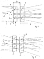
- variable attenuator shown in FIG. 1 and FIG. 2 comprises two multi-aperture apertures 1, 2, which are the same, so that in the following only the first multi-aperture diaphragm. 1 is described in detail.
- the multi-aperture diaphragm 1 comprises a transparent substrate 3, which here is plate-shaped is trained.
- the substrate 3 is made of glass, which is for the supplied electromagnetic radiation beam 4 with a wavelength of 193 nm is transparent.
- the Beam 4 is emitted by an excimer laser, which is not shown here.
- a Absorbing layer 6 of chromium oxide applied which has a plurality of openings 7.
- the Openings are circular here and have a diameter of about 1 mm and are spaced about 1 mm apart.
- the second multi-aperture diaphragm 2 Behind the multi-aperture diaphragm 1, seen in the beam propagation direction A of the beam, the second multi-aperture diaphragm 2 is arranged, wherein the distance D of the two Multiaperture diaphragms 1 and 2 is chosen so that a suitable mixing in transmitted beam 8 about after about 50 cm (distance Z) behind the second Multiaperture 2 is achieved when the divergence of the supplied beam 2 mrad amounts to.
- the weakening position of the attenuator shown in FIG. 1 is a first end position in that in this position the minimum attenuation is achieved.
- FIG. 2 now shows a second attenuation position in which the attenuation is opposite the position of Fig. 1 is greater.
- This is achieved by the second multi-aperture diaphragm 2 is shifted in a direction transverse to the beam propagation direction A.
- Such Displacement can be performed by means of an actuator (not shown) and is through indicated by the double arrow B. Due to the shift, the size of the beam is reduces the effective opening created by the holes 7 in the multi-aperture apertures 1, 2, so that less radiation is transmitted. This achieves the desired attenuation.
- a particular advantage of the attenuator according to the invention is that the Attenuation over the entire cross section of the transmitted beam 8 in is essentially the same. Also, the cross section of the beam 4, 8 through the Attenuator not or hardly changed practically. Thus, it is with the erfindunlicen variable attenuator possible, a stepless attenuation of an electromagnetic Beam to perform. This is especially possible with UV radiation, in this case, a particular advantage is that the attenuator a has excellent durability, since materials absorbing at these wavelengths desired durability are available and the mitigation via geometric parameters (Dimensions and arrangement of the multi-aperture diaphragms) is set.
- multi-aperture diaphragms 1 and 2 can also be realized as a material aperture, such. etched or drilled sheets of absorbent material.
Landscapes
- Physics & Mathematics (AREA)
- General Physics & Mathematics (AREA)
- Optics & Photonics (AREA)
- Mechanical Light Control Or Optical Switches (AREA)
- Optical Elements Other Than Lenses (AREA)
- Variable-Direction Aerials And Aerial Arrays (AREA)
Applications Claiming Priority (2)
| Application Number | Priority Date | Filing Date | Title |
|---|---|---|---|
| DE2003145782 DE10345782A1 (de) | 2003-10-01 | 2003-10-01 | Variabler Abschwächer |
| DE10345782 | 2003-10-01 |
Publications (1)
| Publication Number | Publication Date |
|---|---|
| EP1521109A1 true EP1521109A1 (fr) | 2005-04-06 |
Family
ID=34306192
Family Applications (1)
| Application Number | Title | Priority Date | Filing Date |
|---|---|---|---|
| EP04021936A Ceased EP1521109A1 (fr) | 2003-10-01 | 2004-09-15 | Atténuateur optique variable |
Country Status (2)
| Country | Link |
|---|---|
| EP (1) | EP1521109A1 (fr) |
| DE (1) | DE10345782A1 (fr) |
Cited By (1)
| Publication number | Priority date | Publication date | Assignee | Title |
|---|---|---|---|---|
| CN111555111A (zh) * | 2020-05-19 | 2020-08-18 | 上海科技大学 | 一种硬x射线自由电子激光固体衰减器及衰减控制方法 |
Families Citing this family (1)
| Publication number | Priority date | Publication date | Assignee | Title |
|---|---|---|---|---|
| JP6370766B2 (ja) | 2015-11-13 | 2018-08-08 | ファナック株式会社 | レーザ用パワーセンサ |
Citations (4)
| Publication number | Priority date | Publication date | Assignee | Title |
|---|---|---|---|---|
| DE2836861A1 (de) * | 1977-09-14 | 1979-03-22 | Juerg Nigg | Verfahren zum kontinuierlichen veraendern der lichtdurchlaessigkeit eines lichtmodulators sowie lichtmodulator |
| US5191374A (en) * | 1988-11-17 | 1993-03-02 | Nikon Corporation | Exposure control apparatus |
| EP0899596A2 (fr) * | 1997-08-28 | 1999-03-03 | Salvatore Cali' | Système d'écran imprimé pour commande du passage de la lumière et du champ de vision |
| US20030067591A1 (en) * | 2001-09-18 | 2003-04-10 | Hideki Komatsuda | Illumination optical system, exposure apparatus, and microdevice manufacturing method |
Family Cites Families (4)
| Publication number | Priority date | Publication date | Assignee | Title |
|---|---|---|---|---|
| US4761057A (en) * | 1987-02-19 | 1988-08-02 | General Electric Company | Aperture member for photo plotting apparatus |
| US5062689A (en) * | 1990-08-21 | 1991-11-05 | Koehler Dale R | Electrostatically actuatable light modulating device |
| DE4212077A1 (de) * | 1992-04-10 | 1993-10-14 | Fraunhofer Ges Forschung | Piezoelektrisch verstellbares Ventil und Verfahren zu ihrer Herstellung |
| EP0628796B1 (fr) * | 1993-06-09 | 1996-08-28 | Hewlett-Packard GmbH | Composant optique ajustable |
-
2003
- 2003-10-01 DE DE2003145782 patent/DE10345782A1/de not_active Withdrawn
-
2004
- 2004-09-15 EP EP04021936A patent/EP1521109A1/fr not_active Ceased
Patent Citations (4)
| Publication number | Priority date | Publication date | Assignee | Title |
|---|---|---|---|---|
| DE2836861A1 (de) * | 1977-09-14 | 1979-03-22 | Juerg Nigg | Verfahren zum kontinuierlichen veraendern der lichtdurchlaessigkeit eines lichtmodulators sowie lichtmodulator |
| US5191374A (en) * | 1988-11-17 | 1993-03-02 | Nikon Corporation | Exposure control apparatus |
| EP0899596A2 (fr) * | 1997-08-28 | 1999-03-03 | Salvatore Cali' | Système d'écran imprimé pour commande du passage de la lumière et du champ de vision |
| US20030067591A1 (en) * | 2001-09-18 | 2003-04-10 | Hideki Komatsuda | Illumination optical system, exposure apparatus, and microdevice manufacturing method |
Cited By (2)
| Publication number | Priority date | Publication date | Assignee | Title |
|---|---|---|---|---|
| CN111555111A (zh) * | 2020-05-19 | 2020-08-18 | 上海科技大学 | 一种硬x射线自由电子激光固体衰减器及衰减控制方法 |
| CN111555111B (zh) * | 2020-05-19 | 2021-10-08 | 上海科技大学 | 一种硬x射线自由电子激光固体衰减器及衰减控制方法 |
Also Published As
| Publication number | Publication date |
|---|---|
| DE10345782A1 (de) | 2005-04-21 |
Similar Documents
| Publication | Publication Date | Title |
|---|---|---|
| EP0863588B1 (fr) | Optique pour laser et laser à diode | |
| DE3001059C2 (de) | Röntgenstrahlenlithographiesystem zur Erzeugung von integrierten Schaltungen | |
| DE10108637A1 (de) | Vorrichtung zum Bilden eines homogenisierten Lichtmusters und Verfahren zu ihrer Herstellung | |
| EP2217961A1 (fr) | Dispositif de mise en forme de faisceau | |
| DE2210320C3 (de) | Akusto-optisches Ablenksystem | |
| DE102007052782A1 (de) | Verfahren zur Veränderung der Eigenschaften einer TCO-Schicht | |
| DE10148167A1 (de) | Beleuchtungsanordnung | |
| EP1934647A1 (fr) | Dispositif d'homogeneisation de la lumiere | |
| DE102009037112B4 (de) | Optisches System zum Erzeugen eines Lichtstrahls zur Behandlung eines Substrats | |
| DE3101415C2 (fr) | ||
| EP1789833A1 (fr) | Systeme optique pour convertir une repartition d'intensite primaire en une repartition d'intensite angulaire determinee | |
| WO2014146916A1 (fr) | Dispositif d'homogénéisation d'un rayon laser | |
| DE10322239A1 (de) | Geblazetes diffraktives optisches Element sowie Projektionsobjektiv mit einem solchen Element | |
| WO2009003618A1 (fr) | Dispositif de formation d'un rayonnement laser | |
| CH693474A5 (de) | Neutronenoptisches Bauelement. | |
| DE10313548B4 (de) | Binär geblazetes diffraktives optisches Element sowie ein solches Element enthaltendes Objektiv | |
| DE2638276C3 (de) | Optische Lochblende für lasertechnische Anwendungen | |
| DE2451624A1 (de) | Vorrichtung zum gerichteten uebertragen von elastischen oberflaechenwellen | |
| EP1668422B1 (fr) | Dispositif d'eclairage pour la lithographie | |
| DE102008056315A1 (de) | Vorrichtung zur Homogenisierung von Laserstrahlung sowie Vorrichtung zur Formung von Laserstrahlung | |
| DE4425358C2 (de) | Optische Isolator-Vorrichtung zur Anordnung im Strahlengang zwischen einer Laserstrahlquelle und einem Objekt | |
| EP1438628B1 (fr) | Procede et dispositif de reduction de speckle dans un systeme optique | |
| DE60102766T2 (de) | Optischer Abschwächer mit Polarisationskompensation | |
| DE102021210671A1 (de) | Intensitätsanpassungsfilter für eine optische anordnung und optische anordnung mit einem entsprechenden intensitätsanpassungsfilter sowie verfahren zu dessen herstellung | |
| DE102007048780A1 (de) | Strahlumlenkvorrichtung |
Legal Events
| Date | Code | Title | Description |
|---|---|---|---|
| PUAI | Public reference made under article 153(3) epc to a published international application that has entered the european phase |
Free format text: ORIGINAL CODE: 0009012 |
|
| AK | Designated contracting states |
Kind code of ref document: A1 Designated state(s): AT BE BG CH CY CZ DE DK EE ES FI FR GB GR HU IE IT LI LU MC NL PL PT RO SE SI SK TR |
|
| AX | Request for extension of the european patent |
Extension state: AL HR LT LV MK |
|
| 17P | Request for examination filed |
Effective date: 20050503 |
|
| 17Q | First examination report despatched |
Effective date: 20050617 |
|
| AKX | Designation fees paid |
Designated state(s): AT BE BG CH CY CZ DE DK EE ES FI FR GB GR HU IE IT LI LU MC NL PL PT RO SE SI SK TR |
|
| STAA | Information on the status of an ep patent application or granted ep patent |
Free format text: STATUS: THE APPLICATION HAS BEEN REFUSED |
|
| 18R | Application refused |
Effective date: 20060226 |