EP1521327B1 - Système de modulation et de contrôle de la température de piles à combustible - Google Patents
Système de modulation et de contrôle de la température de piles à combustible Download PDFInfo
- Publication number
- EP1521327B1 EP1521327B1 EP04009879A EP04009879A EP1521327B1 EP 1521327 B1 EP1521327 B1 EP 1521327B1 EP 04009879 A EP04009879 A EP 04009879A EP 04009879 A EP04009879 A EP 04009879A EP 1521327 B1 EP1521327 B1 EP 1521327B1
- Authority
- EP
- European Patent Office
- Prior art keywords
- fuel cell
- fuel
- cells
- cell
- emf
- Prior art date
- Legal status (The legal status is an assumption and is not a legal conclusion. Google has not performed a legal analysis and makes no representation as to the accuracy of the status listed.)
- Expired - Lifetime
Links
- 239000000446 fuel Substances 0.000 title claims description 165
- 238000000034 method Methods 0.000 claims description 27
- 230000007423 decrease Effects 0.000 claims description 20
- 239000001257 hydrogen Substances 0.000 claims description 15
- 229910052739 hydrogen Inorganic materials 0.000 claims description 15
- UFHFLCQGNIYNRP-UHFFFAOYSA-N Hydrogen Chemical compound [H][H] UFHFLCQGNIYNRP-UHFFFAOYSA-N 0.000 claims description 11
- 238000004519 manufacturing process Methods 0.000 claims description 11
- 230000008859 change Effects 0.000 claims description 9
- 239000007787 solid Substances 0.000 claims description 9
- 238000009529 body temperature measurement Methods 0.000 claims description 6
- 239000003792 electrolyte Substances 0.000 description 32
- 239000001301 oxygen Substances 0.000 description 13
- 229910052760 oxygen Inorganic materials 0.000 description 13
- -1 hydrogen ions Chemical class 0.000 description 11
- 239000012528 membrane Substances 0.000 description 9
- 239000000919 ceramic Substances 0.000 description 8
- 239000007800 oxidant agent Substances 0.000 description 8
- 230000020169 heat generation Effects 0.000 description 7
- 239000000203 mixture Substances 0.000 description 7
- 230000001590 oxidative effect Effects 0.000 description 7
- 229910001233 yttria-stabilized zirconia Inorganic materials 0.000 description 7
- OKKJLVBELUTLKV-UHFFFAOYSA-N Methanol Chemical compound OC OKKJLVBELUTLKV-UHFFFAOYSA-N 0.000 description 6
- 239000002245 particle Substances 0.000 description 6
- PXHVJJICTQNCMI-UHFFFAOYSA-N Nickel Chemical compound [Ni] PXHVJJICTQNCMI-UHFFFAOYSA-N 0.000 description 5
- QVGXLLKOCUKJST-UHFFFAOYSA-N atomic oxygen Chemical compound [O] QVGXLLKOCUKJST-UHFFFAOYSA-N 0.000 description 5
- 239000003054 catalyst Substances 0.000 description 5
- 239000005518 polymer electrolyte Substances 0.000 description 5
- 238000005054 agglomeration Methods 0.000 description 4
- 230000002776 aggregation Effects 0.000 description 4
- 230000015572 biosynthetic process Effects 0.000 description 4
- 239000011195 cermet Substances 0.000 description 4
- 238000006243 chemical reaction Methods 0.000 description 4
- 230000001351 cycling effect Effects 0.000 description 4
- 238000010438 heat treatment Methods 0.000 description 4
- 239000000463 material Substances 0.000 description 4
- 229910052751 metal Inorganic materials 0.000 description 4
- 239000002184 metal Substances 0.000 description 4
- VNWKTOKETHGBQD-UHFFFAOYSA-N methane Chemical compound C VNWKTOKETHGBQD-UHFFFAOYSA-N 0.000 description 4
- 230000003647 oxidation Effects 0.000 description 4
- 238000007254 oxidation reaction Methods 0.000 description 4
- BASFCYQUMIYNBI-UHFFFAOYSA-N platinum Chemical compound [Pt] BASFCYQUMIYNBI-UHFFFAOYSA-N 0.000 description 4
- 239000000047 product Substances 0.000 description 4
- XLYOFNOQVPJJNP-UHFFFAOYSA-N water Substances O XLYOFNOQVPJJNP-UHFFFAOYSA-N 0.000 description 4
- 229910002449 CoO3−δ Inorganic materials 0.000 description 3
- 238000001816 cooling Methods 0.000 description 3
- 229910021526 gadolinium-doped ceria Inorganic materials 0.000 description 3
- 239000007789 gas Substances 0.000 description 3
- 229910002119 nickel–yttria stabilized zirconia Inorganic materials 0.000 description 3
- 238000012546 transfer Methods 0.000 description 3
- BVKZGUZCCUSVTD-UHFFFAOYSA-L Carbonate Chemical compound [O-]C([O-])=O BVKZGUZCCUSVTD-UHFFFAOYSA-L 0.000 description 2
- 230000004888 barrier function Effects 0.000 description 2
- WUKWITHWXAAZEY-UHFFFAOYSA-L calcium difluoride Chemical group [F-].[F-].[Ca+2] WUKWITHWXAAZEY-UHFFFAOYSA-L 0.000 description 2
- 230000001627 detrimental effect Effects 0.000 description 2
- 238000009826 distribution Methods 0.000 description 2
- 230000000694 effects Effects 0.000 description 2
- 238000009434 installation Methods 0.000 description 2
- 239000010416 ion conductor Substances 0.000 description 2
- 239000011159 matrix material Substances 0.000 description 2
- 150000002739 metals Chemical class 0.000 description 2
- 229910052759 nickel Inorganic materials 0.000 description 2
- 229910052697 platinum Inorganic materials 0.000 description 2
- 230000008569 process Effects 0.000 description 2
- 230000009467 reduction Effects 0.000 description 2
- 239000004065 semiconductor Substances 0.000 description 2
- 239000000758 substrate Substances 0.000 description 2
- 239000010409 thin film Substances 0.000 description 2
- UGFAIRIUMAVXCW-UHFFFAOYSA-N Carbon monoxide Chemical compound [O+]#[C-] UGFAIRIUMAVXCW-UHFFFAOYSA-N 0.000 description 1
- RYGMFSIKBFXOCR-UHFFFAOYSA-N Copper Chemical compound [Cu] RYGMFSIKBFXOCR-UHFFFAOYSA-N 0.000 description 1
- KJTLSVCANCCWHF-UHFFFAOYSA-N Ruthenium Chemical compound [Ru] KJTLSVCANCCWHF-UHFFFAOYSA-N 0.000 description 1
- 229910052772 Samarium Inorganic materials 0.000 description 1
- BQCADISMDOOEFD-UHFFFAOYSA-N Silver Chemical compound [Ag] BQCADISMDOOEFD-UHFFFAOYSA-N 0.000 description 1
- 208000013201 Stress fracture Diseases 0.000 description 1
- BQENXCOZCUHKRE-UHFFFAOYSA-N [La+3].[La+3].[O-][Mn]([O-])=O.[O-][Mn]([O-])=O.[O-][Mn]([O-])=O Chemical compound [La+3].[La+3].[O-][Mn]([O-])=O.[O-][Mn]([O-])=O.[O-][Mn]([O-])=O BQENXCOZCUHKRE-UHFFFAOYSA-N 0.000 description 1
- 229910045601 alloy Inorganic materials 0.000 description 1
- 239000000956 alloy Substances 0.000 description 1
- 238000013459 approach Methods 0.000 description 1
- 229910002091 carbon monoxide Inorganic materials 0.000 description 1
- 229910021525 ceramic electrolyte Inorganic materials 0.000 description 1
- 229910000422 cerium(IV) oxide Inorganic materials 0.000 description 1
- WGLPBDUCMAPZCE-UHFFFAOYSA-N chromium trioxide Inorganic materials O=[Cr](=O)=O WGLPBDUCMAPZCE-UHFFFAOYSA-N 0.000 description 1
- NFYLSJDPENHSBT-UHFFFAOYSA-N chromium(3+);lanthanum(3+);oxygen(2-) Chemical compound [O-2].[O-2].[O-2].[Cr+3].[La+3] NFYLSJDPENHSBT-UHFFFAOYSA-N 0.000 description 1
- 238000002485 combustion reaction Methods 0.000 description 1
- 229920001940 conductive polymer Polymers 0.000 description 1
- 229910052802 copper Inorganic materials 0.000 description 1
- 239000010949 copper Substances 0.000 description 1
- 230000003247 decreasing effect Effects 0.000 description 1
- 238000010586 diagram Methods 0.000 description 1
- 230000005611 electricity Effects 0.000 description 1
- 238000005530 etching Methods 0.000 description 1
- 239000012530 fluid Substances 0.000 description 1
- 239000010436 fluorite Substances 0.000 description 1
- XLYOFNOQVPJJNP-ZSJDYOACSA-N heavy water Substances [2H]O[2H] XLYOFNOQVPJJNP-ZSJDYOACSA-N 0.000 description 1
- 150000004678 hydrides Chemical class 0.000 description 1
- 229930195733 hydrocarbon Natural products 0.000 description 1
- 150000002430 hydrocarbons Chemical class 0.000 description 1
- 150000002431 hydrogen Chemical class 0.000 description 1
- GPRLSGONYQIRFK-UHFFFAOYSA-N hydron Chemical compound [H+] GPRLSGONYQIRFK-UHFFFAOYSA-N 0.000 description 1
- 150000002500 ions Chemical class 0.000 description 1
- 229910002075 lanthanum strontium manganite Inorganic materials 0.000 description 1
- 239000007788 liquid Substances 0.000 description 1
- 238000005259 measurement Methods 0.000 description 1
- 239000002905 metal composite material Substances 0.000 description 1
- 239000003345 natural gas Substances 0.000 description 1
- 230000033116 oxidation-reduction process Effects 0.000 description 1
- 239000012466 permeate Substances 0.000 description 1
- 238000010248 power generation Methods 0.000 description 1
- 239000012078 proton-conducting electrolyte Substances 0.000 description 1
- 230000008707 rearrangement Effects 0.000 description 1
- 229910052703 rhodium Inorganic materials 0.000 description 1
- 239000010948 rhodium Substances 0.000 description 1
- MHOVAHRLVXNVSD-UHFFFAOYSA-N rhodium atom Chemical compound [Rh] MHOVAHRLVXNVSD-UHFFFAOYSA-N 0.000 description 1
- 229910052707 ruthenium Inorganic materials 0.000 description 1
- KZUNJOHGWZRPMI-UHFFFAOYSA-N samarium atom Chemical compound [Sm] KZUNJOHGWZRPMI-UHFFFAOYSA-N 0.000 description 1
- 229910052709 silver Inorganic materials 0.000 description 1
- 239000004332 silver Substances 0.000 description 1
- 239000011973 solid acid Substances 0.000 description 1
- 239000007858 starting material Substances 0.000 description 1
- 229910000601 superalloy Inorganic materials 0.000 description 1
- 239000002226 superionic conductor Substances 0.000 description 1
- 230000002277 temperature effect Effects 0.000 description 1
- 239000002699 waste material Substances 0.000 description 1
Images


Classifications
-
- H—ELECTRICITY
- H01—ELECTRIC ELEMENTS
- H01M—PROCESSES OR MEANS, e.g. BATTERIES, FOR THE DIRECT CONVERSION OF CHEMICAL ENERGY INTO ELECTRICAL ENERGY
- H01M8/00—Fuel cells; Manufacture thereof
- H01M8/04—Auxiliary arrangements, e.g. for control of pressure or for circulation of fluids
- H01M8/04298—Processes for controlling fuel cells or fuel cell systems
- H01M8/04313—Processes for controlling fuel cells or fuel cell systems characterised by the detection or assessment of variables; characterised by the detection or assessment of failure or abnormal function
- H01M8/0432—Temperature; Ambient temperature
-
- H—ELECTRICITY
- H01—ELECTRIC ELEMENTS
- H01M—PROCESSES OR MEANS, e.g. BATTERIES, FOR THE DIRECT CONVERSION OF CHEMICAL ENERGY INTO ELECTRICAL ENERGY
- H01M8/00—Fuel cells; Manufacture thereof
- H01M8/04—Auxiliary arrangements, e.g. for control of pressure or for circulation of fluids
- H01M8/04007—Auxiliary arrangements, e.g. for control of pressure or for circulation of fluids related to heat exchange
- H01M8/04067—Heat exchange or temperature measuring elements, thermal insulation, e.g. heat pipes, heat pumps, fins
-
- H—ELECTRICITY
- H01—ELECTRIC ELEMENTS
- H01M—PROCESSES OR MEANS, e.g. BATTERIES, FOR THE DIRECT CONVERSION OF CHEMICAL ENERGY INTO ELECTRICAL ENERGY
- H01M8/00—Fuel cells; Manufacture thereof
- H01M8/04—Auxiliary arrangements, e.g. for control of pressure or for circulation of fluids
- H01M8/04298—Processes for controlling fuel cells or fuel cell systems
- H01M8/04694—Processes for controlling fuel cells or fuel cell systems characterised by variables to be controlled
- H01M8/04858—Electric variables
- H01M8/04925—Power, energy, capacity or load
- H01M8/0494—Power, energy, capacity or load of fuel cell stacks
-
- H—ELECTRICITY
- H01—ELECTRIC ELEMENTS
- H01M—PROCESSES OR MEANS, e.g. BATTERIES, FOR THE DIRECT CONVERSION OF CHEMICAL ENERGY INTO ELECTRICAL ENERGY
- H01M8/00—Fuel cells; Manufacture thereof
- H01M8/10—Fuel cells with solid electrolytes
- H01M8/12—Fuel cells with solid electrolytes operating at high temperature, e.g. with stabilised ZrO2 electrolyte
- H01M2008/1293—Fuel cells with solid oxide electrolytes
-
- H—ELECTRICITY
- H01—ELECTRIC ELEMENTS
- H01M—PROCESSES OR MEANS, e.g. BATTERIES, FOR THE DIRECT CONVERSION OF CHEMICAL ENERGY INTO ELECTRICAL ENERGY
- H01M8/00—Fuel cells; Manufacture thereof
- H01M8/24—Grouping of fuel cells, e.g. stacking of fuel cells
- H01M8/249—Grouping of fuel cells, e.g. stacking of fuel cells comprising two or more groupings of fuel cells, e.g. modular assemblies
-
- Y—GENERAL TAGGING OF NEW TECHNOLOGICAL DEVELOPMENTS; GENERAL TAGGING OF CROSS-SECTIONAL TECHNOLOGIES SPANNING OVER SEVERAL SECTIONS OF THE IPC; TECHNICAL SUBJECTS COVERED BY FORMER USPC CROSS-REFERENCE ART COLLECTIONS [XRACs] AND DIGESTS
- Y02—TECHNOLOGIES OR APPLICATIONS FOR MITIGATION OR ADAPTATION AGAINST CLIMATE CHANGE
- Y02E—REDUCTION OF GREENHOUSE GAS [GHG] EMISSIONS, RELATED TO ENERGY GENERATION, TRANSMISSION OR DISTRIBUTION
- Y02E60/00—Enabling technologies; Technologies with a potential or indirect contribution to GHG emissions mitigation
- Y02E60/30—Hydrogen technology
- Y02E60/50—Fuel cells
-
- Y—GENERAL TAGGING OF NEW TECHNOLOGICAL DEVELOPMENTS; GENERAL TAGGING OF CROSS-SECTIONAL TECHNOLOGIES SPANNING OVER SEVERAL SECTIONS OF THE IPC; TECHNICAL SUBJECTS COVERED BY FORMER USPC CROSS-REFERENCE ART COLLECTIONS [XRACs] AND DIGESTS
- Y02—TECHNOLOGIES OR APPLICATIONS FOR MITIGATION OR ADAPTATION AGAINST CLIMATE CHANGE
- Y02P—CLIMATE CHANGE MITIGATION TECHNOLOGIES IN THE PRODUCTION OR PROCESSING OF GOODS
- Y02P70/00—Climate change mitigation technologies in the production process for final industrial or consumer products
- Y02P70/50—Manufacturing or production processes characterised by the final manufactured product
Definitions
- the subject matter disclosed herein pertains to power modulation of fuel cells and temperature control of fuel cells.
- EP 1 294 039 A1 concerns a small fuel cell employing a polymer electrolyte thin film, by using a semiconductor process.
- a polymer electrolyte thin film fuel cell comprises a substrate having a plurality of openings; an electrolyte membrane-electrode assembly formed on the substrate so as to cover each of the openings, the assembly comprising a first catalyst electrode layer, a hydrogen ion conductive polymer electrolyte membrane and a second catalyst electrode layer which are formed successively; and fuel and oxidant supply means for supplying a fuel or an oxidant gas to the first catalyst electrode layer through the openings, and an oxidant gas or a fuel to the second catalyst electrode layer.
- US 6,312,846 B1 discloses a fuel cell which is formed on a semiconductor wafer by etching channel in the wafer and forming a proton exchange membrane PEM barrier in the etched channel.
- the barrier divides the channel into two.
- a hydrogen fuel is admitted into one of the divided channels and an oxidant into the other.
- the hydrogen reacts with a catalyst formed on an anode electrode at the hydrogen side of the channel to release hydrogen ions (protons) which are absorbed into the PEM.
- the protons migrate through the PEM and recombine with return hydrogen electrons on a cathode electrode on the oxygen side of the PEM and the oxygen to form water
- US 2002/0187375 A describes a fuel cell installation and a method for operating a fuel cell installation with a dynamic power control are provided.
- the dynamic power control is achieved by additionally connecting at least one subsystem which is kept ready for operation, a starter system and/or a low-voltage unit for nighttime operation and/or an on-board power supply.
- An exemplary system includes a first fuel cell capable of providing an electrical output, a second fuel cell capable of providing an electrical output, and a switch circuit that includes one or more switches for arranging the electrical output of the first fuel cell and the electrical output of the second fuel cell in parallel or series to thereby adjust electrical output efficiency and heat production.
- a fuel cell can generate electricity and heat by electrochemically reacting a fuel and an oxidizer using an ion conducting electrolyte for transfer of charged species without combustion.
- a typical fuel cell may generate an electrical potential through conversion of energy stored in a fuel (e.g., hydrogen, natural gas, methanol, etc.) and an oxidant (e.g., oxygen).
- a fuel e.g., hydrogen, natural gas, methanol, etc.
- an oxidant e.g., oxygen
- Fig. 1 shows a prior art solid oxide fuel cell 100.
- the fuel cell 100 includes an anode 110, a cathode 114 and an electrolyte 118.
- the anode 110 and the cathode 114 are electrodes while the electrolyte 118 serves as a type of membrane.
- an oxidant containing gas such as air is provided to the cathode 114, which may be referred to as an "air electrode”
- a fuel is provided to the anode 110, which may be referred to as a "fuel electrode”.
- the cathode 114 may receive oxygen (from air) and the anode 110 may receive hydrogen (and optionally carbon monoxide, methane and other hydrocarbons).
- oxygen and hydrogen react to form water. This reaction is exothermic and it has an associated potential whereby the fuel cell 100 provides a flow path for electrons according to the potential.
- the electrolyte 118 acts as a type of membrane, for example, an ion-conducting membrane.
- the electrolyte 118 is an oxygen ion conducting membrane. If H 2 is used as a fuel, two protons or hydrogen ions are formed at the anode 110 from each H 2 molecule due to removal of electrons. An electron flow path or circuit 124 allows these electrons to become available at the cathode 114, which helps to drive oxygen ion formation from O 2 . Oxygen ions conduct or permeate the electrolyte 118 and the anode 110, where the oxygen ions form water with protons or hydrogen ions.
- the electrochemical process may be represented by the following reaction equations: O 2 +4e - ⁇ 2O 2- 2H 2 ⁇ 4H + + 4e - 4H + + 2O 2- ⁇ 2H 2 O
- a hydrogen-oxygen fuel cell according to the reaction equations has an EMF of approximately 1.2 V.
- an electrolyte should have a high transport rate for desired ionic species while preventing transport of unwanted species.
- Various ceramics e.g., electroceramics
- electroceramics have properties suitable for use as electrolyte.
- a group of electroceramics referred to sometimes as “fast ion conductors", “rapid ion conductors” or “superionic conductors”, may support high transport rates for desired ionic species.
- a commonly used ceramic for oxygen ion ion-conducting membranes is yttria stabilized zirconia (YSZ).
- YSZ electrolyte For an YSZ electrolyte to provide sufficient oxygen ion conductivity, fairly high temperatures are required (e.g., typically greater than 700°C), even for a thin electrolyte (e.g., less than approximately 10 ⁇ m). Of course, numerous costs are associated with operation at such high temperatures. For example, high cost alloys (e.g., superalloys, etc.) may be required as a fuel cell housing thereby increasing cost substantially. Stresses at such operating temperatures may also degrade anodes, cathodes and/or electrolytes and thereby increase cost. For example, a cathode may have a coefficient of thermal expansion that differs from that of an electrolyte.
- high cost alloys e.g., superalloys, etc.
- Stresses at such operating temperatures may also degrade anodes, cathodes and/or electrolytes and thereby increase cost.
- a cathode may have a coefficient of thermal expansion that differs from that
- operating temperatures and/or temperature cycling may have a detrimental impact on anode, cathode and/or electrolyte characteristics.
- one or more metal components in an anode may have a tendency to agglomerate above certain temperatures.
- Temperature and/or oxidation-reduction cycling may also promote agglomeration.
- Agglomeration is known to occur in Ni-YSZ cermet anodes of solid oxide fuel cells and to be generally related to factors such as current density and fuel utilization. For example, evenly distributed nickel particles are desirable to maximize the interface or three-phase-boundary (TPB) between an anode and an electrolyte. Agglomeration occurs throughout an anode and causes an increase in "particle size" and a reduction in evenness of particle distribution. These effects decrease effective TPB and thereby increase anode losses. Eventually, a disparate distribution may result that wholly compromises interparticle (or interagglomerate) conductivity.
- An agglomerate may further degrade an electrode upon oxidation. Oxidation typically occurs during and after cooling (e.g., as a part of a fuel cell's operational cycling).
- Ni-YSZ cermet anodes Ni particles or agglomerates typically oxidize during and/or after cooling. Upon oxidation, the particles or agglomerates increase in size. After a few heating and cooling cycles particles or agglomerates may become large enough to exert significant forces (e.g., stress) on, in this example, the ceramic YSZ matrix. Thus, oxidation and/or agglomeration may degrade or break a matrix and render an electrode inoperable or prohibitively inefficient.
- a ceramic and metal composite may serve as an anode while Sr-doped lanthanum manganite (La 1-x Sr x MnO 3 ) may serve as a cathode.
- Sr-doped lanthanum manganite La 1-x Sr x MnO 3
- various other materials may be used for the anode 110 or the cathode 114.
- a plurality of fuel cells may be grouped to form an array or "stack".
- an interconnect is often used to join anodes and cathodes, for example, an interconnect that includes a doped lanthanum chromite (e.g., La 0.8 Ca 0.2 CrO 3 ).
- a doped lanthanum chromite e.g., La 0.8 Ca 0.2 CrO 3
- other materials may be suitable.
- a fuel cell may be one of solid oxide fuel cells (SOFCs), proton conducting ceramic fuel cells, alkaline fuel cells, polymer electrolyte membranes (PEM) fuel cells, molten carbonate fuel cells, solid acid fuel cells, direct methanol PEM fuel cells and others (see, e.g., other examples below).
- SOFCs solid oxide fuel cells
- PEM polymer electrolyte membranes
- molten carbonate fuel cells solid acid fuel cells
- direct methanol PEM fuel cells direct methanol PEM fuel cells and others (see, e.g., other examples below).
- Various exemplary fuel cells presented herein are solid oxide fuel cells.
- An electrolyte may be formed from any suitable material.
- Various exemplary electrolytes as presented herein are at least one of oxygen ion conducting membrane electrolytes, proton conducting electrolytes, carbonate (CO 3 2- ) conducting electrolytes, OH - conducting electrolytes, hydride ion (H - ) conducting and mixtures thereof.
- oxygen ion conducting membrane electrolytes proton conducting electrolytes
- carbonate (CO 3 2- ) conducting electrolytes OH - conducting electrolytes
- OH - conducting electrolytes hydride ion (H - ) conducting and mixtures thereof.
- hydride ion electrolyte fuel cells advances have been recently been demonstrated for molten hydride electrolyte fuel cell.
- exemplary electrolytes are at least one of cubic fluorite structure electrolytes, doped cubic fluorite electrolytes, proton-exchange polymer electrolytes, proton-exchange ceramic electrolytes, and mixtures thereof.
- an exemplary electrolyte is at least one of yttria-stabilized zirconia, samarium doped-ceria, gadolinium doped-ceria, La a Sr b Ga c Mg d O 3- ⁇ , and mixtures thereof, which may be particularly suited for use in solid oxide fuel cells.
- Anode and cathode may be formed from any suitable material, as desired and/or necessitated by a particular end use.
- Various exemplary anodes and/or cathodes are at least one of metal(s), ceramic(s) and cermet(s).
- metals which may be suitable for an anode include at least one of nickel, copper, platinum and mixtures thereof.
- ceramics which may be suitable for an anode include at least one of Ce x Sm y O 2- ⁇ , Ce x Gd y O 2- Ce x Gd y O 2- ⁇ , La x Sr y Cr z O 3- ⁇ , and mixtures thereof.
- Some non-limitative examples of cermets which may be suitable for an anode include at least one of Ni-YSZ, Cu-YSZ, Ni-SDC, Ni-GDC, Cu-SDC, Cu-GDC, and mixtures thereof.
- Some non-limitative examples of metals which may be suitable for a cathode include at least one of silver, platinum, ruthenium, rhodium and mixtures thereof.
- Some non-limitative examples of ceramics which may be suitable for a cathode include at least one of Sm x Sr y CoO 3- ⁇ , Ba x La y CoO 3- ⁇ , Gd x Sr y CoO 3- ⁇ .
- thermodynamic efficiency For water as a product, enthalpy of formation may be given as a "higher heating value” (HHV) corresponding to liquid or as a “lower heating value” (LHV) corresponding to vapor (e.g., steam).
- HHV higher heating value
- LHV lower heating value
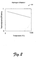
- the thermodynamic efficiency ( ⁇ Thermo ) generally decreases with respect to an increase in temperature due to a temperature related decrease in the Gibbs free energy (e.g., due to temperature and entropy term of the free energy equation).
- Fig. 2 shows a plot 200 representative of the relationship between theoretical thermodynamic efficiency and temperature for hydrogen utilization.
- EMF - ⁇ F f / 2 ⁇ F
- F Faraday's constant (96,485 coulombs).
- the total efficiency inherently depends on temperature due to the dependence of EMF on temperature, according to the theoretical thermodynamic efficiency. However, other temperature effects may be considered. Fig.
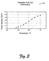
- FIG. 3 shows a plot 300 of power density versus temperature for a cell wherein lower temperatures correspond to lower power densities. Hence, power generation capability of a cell is inhibited by a decrease in cell temperature as shown in plot 300. Further, a decrease in power will typically cool a cell.
- Fig. 4A shows a plot 410 of cell EMF and power density versus current density for an exemplary fuel cell at a temperature of approximately 700°C.
- cell EMF decreases with respect to an increase in current density.
- Power density is defined as current density multiplied by EMF; hence, power density exhibits a maximum with respect to current density.
- An increase in temperature above 700°C for this exemplary cell will initially increase power density but in time could degrade cell performance.
- a decrease in temperature will result in a significant decrease in EMF and hence power density.
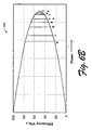
- Fig. 4B shows a plot 420 of cell EMF efficiency versus power density for an exemplary fuel cell at a temperature of approximately 700°C.
- cell EMF decreases and hence, cell EMF efficiency decreases.
- LHV EMF
- an efficiency of 80% would correspond to an EMF of approximately 0.9 V.
- From the plot 410 such a cell would be operating at a current density of approximately 0.36 Acm -2 and a power density of approximately 0.3 Wcm -2 .
- a cell is operating at an EMF efficiency of 60% or an EMF of approximately 0.7 V.
- an EMF of approximately 0.7 V corresponds to a current density of approximately 0.6 Acm -2 , which yields a power density of approximately 0.42 Wcm -2 .
- the same power density may be achieved using a different EMF efficiency as well.
- an EMF efficiency of approximately 30% corresponds to an EMF of approximately 0.36 V and a current density of approximately 1.18 Acm -2 .
- a cell having 1 cm 2 a load that requires a power of approximately 0.42 W can be powered by the cell operating at a high EMF efficiency state or a low EMF efficiency state.
- the high EMF efficiency state corresponds to a high EMF and a low current while the low EMF efficiency state corresponds to a low EMF and a high current.
- a cell is optionally switched between a high EMF efficiency state and a low EMF efficiency state while maintaining a constant power output.
- more fuel is utilized or consumed when compared to the high EMF efficiency state.
- Table 1 below summarizes conditions associated with a low efficiency state (State 1) and a high efficiency state (State 2): Table 1. Operational States State 1 State 2 EMF Efficiency Low High Power Equal to State 2 Equal to State 1 Fuel Consumption High (higher T) Low (lower T)
- Fig. 5A and Fig. 5B further illustrate this principle as it may apply to a series cell system and a parallel cell system, which, as discussed further below, are optionally capable of being switched between series and parallel operation.
- Fig. 5A shows a plot 510 of power versus current for a series cell system having two cells arranged in series and for a parallel cell system having two cells arranged in parallel.
- the maximum power of the series cell system equals the maximum power of parallel cell system; however, these maxima occur at different currents.
- the maximum power of the series cell system occurs at a lesser current than the maximum power of the parallel cell system.
- the plot 510 includes a point 515 where power and current are equal for the series cell system and the parallel cell system.
- the point 515 corresponds to a region of decreasing power with respect to increasing current for the series cell system and to a region of an increasing power with respect to increasing current for the parallel cell system.
- a switchable cell system can be switched from a high efficiency state to a low efficiency state or vise versa. Further, such a switch in configuration and hence efficiency at this point occurs without a change in current or voltage output of the two cell system.
- Fig. 5B shows a plot 520 of efficiency versus power that corresponds to the series cell system and the parallel cell system of the plot 510 of Fig. 5A .
- a power maximum exists for an efficiency that is less than some maximum efficiency and at this power maximum, switching a switchable two cell system between a series and a parallel configuration does not result in a change in efficiency.
- the point 515 where power and current coincide for the series and the parallel configuration is at a power that is less than the maximum power.
- a change in efficiency will occur when switching from a series configuration to a parallel configuration for the exemplary two cell system.
- 5B represents a shift from a series to a parallel configuration or vice versa.
- a parallel configuration corresponds to a higher efficiency and a series configuration corresponds to a lower efficiency.
- Fig. 5A and Fig. 5B show conditions for two configurations, the number of possible configurations increases as the number of cells in a system increases.
- Fig. 6A shows a plot 610 of power versus current for an exemplary switchable cell system having four cells and five possible configurations. As configuration of the system takes on a more parallel configuration, the power versus current curve occurs over a wider range of current; hence, for such a configuration trend, the maximum power will occur at increasingly higher currents.
- the plot 610 illustrates that nine points exist (labeled a-j) where the exemplary system configuration may be switched while maintaining power and current. Further, all of these points correspond to powers less than the maximum power and hence correspond to changes in efficiency. Yet further, none of the points correspond to more than two configurations. Thus, in this example, no points exist where a change between three configurations maintains constant power and current. Of course, for example, in the "3:1" configuration, switching the "1" cell with one of the "3" cells will maintain constant power and current.
- a switch toward a parallel configuration results in a decrease in temperature while a switch toward a series configuration results in an increase in temperature.
- the closer power is to the maximum power the less the temperature will change when switching between configurations.
- a small change in temperature or heat generation may be expected while at point “d” a larger change in temperature or heat generation may be expected.
- a switch from one configuration to another configuration results in a larger efficiency change when compared to a switch at a higher power.
- Fig. 6B shows a plot 620 of efficiency versus power for the exemplary switchable cell system of the plot 610 of Fig. 6A .
- the power axis increases in magnitude.
- a power curve for any given configuration will in general share a common operating point with other configurations as shown in the plot 610 of Fig. 6A .
- Each of these operating points correspond to a unique power output and will shift the switching condition laterally along the efficiency power curve as shown for an exemplary four cell system(see, e.g., the plot 620 of Fig. 6B ).
- a fuel cell system with a large number of cells can have many more potential operating points extending over a near continuous range of power output.
- an operating point is chosen and implemented in an exemplary system tuned for a load specified power requirement.
- Operating points near maximum power output may be expected to generate a small shift in efficiency and thus will produce small shifts in temperature or heat generation over large times compared with operating points further from maximum power value.
- a system operating at a point relatively far from the maximum power output of the system may be expected to produce a large shift in temperature or heat generation over a relatively small time.
- Table 2 summarizes information for the number of possible unique connection configurations (m) and the corresponding number of operating points (N) for various exemplary cell stacks containing between three and eleven individual cells (n). Table 2. Unique Configurations and Total Operating Points Number of cells Number of configurations Number of "points" n m N 3 3 3 4 5 10 5 7 21 6 11 1 55 7 15 105 8 22 231 9 30 435 10 43 903 11 59 1711
- n a relatively small number of cells
- Additional cells e.g., n > 11
- a cell is supplied a constant amount of fuel, for example, according to a low EMF efficiency state (e.g., a more serial configuration) and then switched to a high EMF efficiency state (e.g., a more parallel configuration)
- a high EMF efficiency state e.g., a more parallel configuration
- fuel efficiency which is typically defined as amount of fuel reacted divided amount of fuel supplied
- fuel may become limiting, or alternatively, fuel efficiency will increase because the low state utilizes more fuel than the high state.
- a switch from a low EMF efficiency state to a high EMF efficiency state results in excess fuel while a switch from a high EMF efficiency state to a low EMF efficiency state results in a decrease in excess fuel (e.g., perhaps even a limiting amount of fuel).
- a multiple cell system may operate at more than one state while maintaining a constant power output at a constant current and voltage condition.
- cell EMF and current density are variable parameters that are related to fuel consumption, EMF efficiency, etc.
- An exemplary arrangement allows for at least some cells in multiple cell system to be switched between parallel and series electrical arrangements. First, various exemplary arrangements are described and then various methods of operating the exemplary arrangement are described that account for power and fuel considerations.
- At least some cells in a multiple cell system are operated in series and/or parallel.
- cells are electrically connected in series (e.g., a positive terminal of one cell connected to a negative terminal of another cell, etc.)
- the total voltage output of the cells is equal to the sum of the individual cell voltages.
- the current flow through a cell connected in series is the same as for a single cell.
- cells are connected in parallel (e.g., positive terminals connected together and negative terminals connected together)
- current capacity increases.
- the total voltage output of cells connected in parallel is the same as that of a single cell, assuming the cells have substantially equal voltage outputs.
- connecting cells in parallel has an effect somewhat analogous to increasing size of electrodes and electrolyte in a single cell.
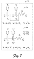
- FIG. 7 shows schematics 700 of two exemplary arrangements 710, 720.
- a parallel arrangement 710 includes a first cell operating at a temperature T 1 and producing an EMF V 1 and a second cell operating at a temperature T 2 and producing an EMF V 2 wherein V 1 equals V 2 .
- a load, represented by a resistor has a resistance R L .
- the temperature measuring circuits for the first cell and the second cell are optional.
- the load experiences an EMF V P that is equal to EMF V 1 and EMF V 2 .
- the arrangement produces a current I P and a power P equal to the product of I P and V P .
- each cell provides only part of the current I P .
- a series arrangement 720 includes a first cell operating at a temperature T 1 ' and producing an EMF V 1 ' and a second cell operating at a temperature T 2 ' and producing an EMF V 2 ' wherein V 1 ' may equal V 2 '.
- a load represented by a resistor has a resistance R L , as in the parallel arrangement 710.
- the temperature measuring circuits for the first cell and the second cell are optional.
- the load experiences an EMF V P that is equal to EMF V 1 ' plus EMF V 2 '. Further, the arrangement produces a current I P and a power P equal to the product of I P and V P .
- each cell provides a current I P .
- a comparison of the exemplary parallel arrangement 710 to the exemplary series arrangement 720 indicates that V 1 ' is less than V P (as well as V 1 and V 2 ) and that V 2 ' is less than V P (as well as V 1 and V 2 ). Further, in the exemplary parallel arrangement 710, the current demand I P is distributed between the two cells whereas each cell in the exemplary arrangement 720 must supply the current demand I P . Thus, given the load having resistance R L and an EMF demand of V P , the exemplary series arrangement 720 may be associated with a low EMF efficiency state of operation (low EMF, high current) when compared to the exemplary parallel arrangement 710 (high EMF, low current).
- an exemplary manner of switching from a high EMF efficiency state to a low EMF efficiency state includes switching from a parallel arrangement of cells to a series arrangement of cells.
- the switching may be expected to maintain a relatively constant power and current given a particular voltage or load.
- Fig. 8 shows an exemplary switchable arrangement of cells 800.
- the exemplary arrangement 800 includes a load having a resistance R L connected to a switchable circuit having two parallel switches SP 1 , SP 2 , one series switch S s and two cells FC 1 and FC 2 . Also shown are temperature measurement circuits T 1 for FC 1 and T 2 for FC 2 , which may be optional, substituted for or in addition to one or more circuits that measure other conditions (e.g., oxidant concentrations, waste product concentrations, etc.).
- switches SP 1 , SP 2 are closed and switch S s is open, then the circuit operates the cells in parallel whereas when switches SP 1 , SP 2 are open and switch S s is closed, the circuit operates the cells in series.
- an exemplary system includes a first fuel cell capable of providing an electrical output, a second fuel cell capable of providing an electrical output and a switch circuit that includes one or more switches for arranging the electrical output of the first fuel cell and the electrical output of the second fuel cell in parallel or series.
- the optional temperature measurement circuits may aid in determining when to switch from parallel to series or from series to parallel. For example, if in a parallel arrangement with an excess fuel supply, T 1 and/or T 2 fall below a set temperature, then a switch to a series arrangement may act to increase heat production and hence temperature.
- a temperature measurement circuit may measure T 1 and/or T 2 and then provide a signal to the switch circuit.
- a controller may control the switch circuit and optionally receive a signal from a temperature measurement circuit or other circuits.
- Fig. 9 shows an exemplary system 900 that includes a plurality of fuel cells 910 (e.g., FC 1 , FC 2 , ... FC N ) and a controller 920.
- the controller 920 controls the electrical arrangement of the fuel cells 910 wherein some or all of the fuel cells are switchable from parallel to series electrical arrangements and from series to parallel electrical arrangements.
- a first set of cells FC 1 and FC 4 may be operating in parallel at an EMF V A while a second set of cells FC 2 , FC 3 , FC 5 , FC 6 , FC 7 and FC 8 are operating in series at an EMF V B wherein V A is substantially equal to V B .
- first set and the second set may be electrically arranged in parallel to a load, which will experience an EMF V A . If the first set of cells FC 1 and FC 4 are switched from parallel to series (e.g., while still in parallel with the second set of cells), then the EMF for cells FC 1 and FC 2 will decrease and the first set of cells will be shifted to a lower EMF efficiency.
- an exemplary method includes a supply block, wherein an excess amount of fuel is supplied to a multiple fuel cell system.
- a switch block At least some of the cells are switched from a parallel to a series electrical arrangement.
- switching maintains a constant power output to one or more loads.
- switching cells from a parallel to a series electrical arrangement can also switch the cells from a high EMF efficiency state to a low EMF efficiency state.
- the exemplary method includes a production block, wherein heat is produced from at least some of the excess fuel because the low EMF efficiency state associated with the cells switched from parallel to series requires more fuel (e.g., a higher fuel utilization).
- the switch increases the fuel efficiency for the switched cells, which was defined as amount of fuel reacted to amount of fuel supplied.
- the production of heat associated with the increase in fuel reacted or utilized causes an increase in temperature of the cells.
- the aforementioned exemplary method would cause T 1 ' to be greater than T 1 and T 2 ' to be greater than T 2 .
- the exemplary method may switch the same cells and/or other cells in a multiple cell system from a series to a parallel electrical arrangement. Such a switch would decrease fuel utilization, assuming a constant supply of fuel, and thereby decrease heat production and hence temperature.
- a switch from parallel to series may aim to increase the temperature of cells FC 1 and FC 4 .
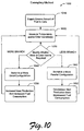
- Fig. 10 shows a block diagram of another exemplary method 1000.
- the exemplary method 1000 includes a fuel supply block 1010, wherein an excess amount of fuel is supplied to a system of fuel cells.
- a measurement block 1020 temperature and/or one or more other variables are measured or otherwise determined.
- a decision block 1030 a decision is made as to whether more or less heat generation is desired.
- the exemplary method 1000 then continues down a less heat generation branch or a more heat generation branch.
- the more branch includes a switching block 1040 that switches the multicell system to a more series configuration (e.g., electrical arrangement) whereas the less branch includes a switching block 1042 that switches the multicell system to a more parallel configuration (e.g., electrical arrangement). Accordingly, the more branch increases heat production in a heat production block 1050 due to increased fuel consumption while the less branch decreases heat production in a heat reduction block 1052 due to a decrease in fuel consumption.
Landscapes
- Life Sciences & Earth Sciences (AREA)
- Engineering & Computer Science (AREA)
- Manufacturing & Machinery (AREA)
- Sustainable Development (AREA)
- Sustainable Energy (AREA)
- Chemical & Material Sciences (AREA)
- Chemical Kinetics & Catalysis (AREA)
- Electrochemistry (AREA)
- General Chemical & Material Sciences (AREA)
- Fuel Cell (AREA)
Claims (9)
- Système comprenant :◆ une première pile à combustible (FC1) capable de fournir une sortie électrique ;◆ une deuxième pile à combustible (FC2) capable de fournir une sortie électrique ;◆ un circuit de commutation qui comprend un ou plusieurs commutateur(s) (SP1, SP2, SS) destiné(s) à agencer la sortie électrique de la première pile à combustible (FC1) et la sortie électrique de la deuxième pile à combustible (FC2) en parallèle ou en série ; et◆ un circuit de mesure de la température (T1, T2) capable de mesurer la température de la première pile à combustible (FC1) ou de la deuxième pile à combustible (FC2) et de fournir un signal au circuit de commutation de façon à ajuster le rendement de la force électromotrice et la production de chaleur de la première et de la deuxième piles à combustible (FC1, FC2).
- Système selon la revendication 1, dans lequel la première pile à combustible (FC1) et la deuxième pile à combustible (FC2) comprennent des piles à combustible à oxyde solide.
- Système selon la revendication 1, comprenant en outre un contrôleur (920) destiné à contrôler le circuit de commutation, dans lequel le contrôleur (920) est optionnellement configuré afin de recevoir le signal de la part du circuit de mesure de la température (T1, T2) et d'agencer la sortie électrique de la première pile à combustible (FC1) et la sortie électrique de la deuxième pile à combustible (FC2) en réponse à celui-ci, dans lequel le contrôleur (920) provoque optionnellement l'agencement en parrallèle de la sortie électrique de la première pile à combustible (FC1) et de la sortie électrique de la deuxième pile à combustible (FC2) par le circuit de commutation afin d'augmenter le rendement de la force électromotrice de la première pile à combustible (FC1) et de la deuxième pile à combustible (FC2), et dans lequel le contrôleur (920) provoque optionnellement l'agencement en série de la sortie électrique de la première pile à combustible (FC1) et de la sortie électrique de la deuxième pile à combustible (FC2) par le circuit de commutation afin de diminuer le rendement de la force électromotrice de la première pile à combustible (FC1) et de la deuxième pile à combustible (FC2).
- Procédé comprenant les étapes consistant à :◆ fournir une quantité excessive de combustible à un système à plusieurs piles à combustible ;◆ commuter au moins certaines des piles à combustible (FC1, FC2) d'un agencement électrique en parallèle à un agencement électrique en série ; et◆ produire de la chaleur à partir d'au moins une partie de la quantité excessive de combustible de façon à contrôler ainsi la température du système de piles à combustible.
- Procédé selon la revendication 4, dans lequel le combustible comprend de l'hydrogène et dans lequel le système à plusieurs piles à combustible comprend optionnellement des piles à combustible à oxyde solide.
- Procédé selon la revendication 4, dans lequel la commutation ne change pas la puissance fournie à une charge.
- Procédé selon la revendication 4, dans lequel la commutation a lieu en réponse à la mesure de la température d'une pile à combustible, identique ou inférieure à une température définie.
- Procédé comprenant les étapes consistant à :◆ fournir une quantité sensiblement constante de combustible à un système à plusieurs piles à combustible ;◆ décider si il est nécessaire ou non d'augmenter la production de chaleur par le système ;◆ en réponse à la décision, commuter au moins certaines des piles à combustible (FC1, FC2) d'un agencement électrique en parallèle à un agencement électrique en série ;◆ moyennant quoi la commutation diminue le rendement de la force électromotrice, et augmente le rendement énergétique de façon à augmenter ainsi la production de chaleur.
- Procédé selon la revendication 8, dans lequel le combustible comprend de l'hydrogène et dans lequel le système à plusieurs piles à combustible comprend optionnellement des piles à combustible à oxyde solide.
Applications Claiming Priority (2)
| Application Number | Priority Date | Filing Date | Title |
|---|---|---|---|
| US10/674,053 US20050069740A1 (en) | 2003-09-29 | 2003-09-29 | Fuel cell modulation and temperature control |
| US674053 | 2003-09-29 |
Publications (3)
| Publication Number | Publication Date |
|---|---|
| EP1521327A2 EP1521327A2 (fr) | 2005-04-06 |
| EP1521327A3 EP1521327A3 (fr) | 2005-07-13 |
| EP1521327B1 true EP1521327B1 (fr) | 2008-06-11 |
Family
ID=34313955
Family Applications (1)
| Application Number | Title | Priority Date | Filing Date |
|---|---|---|---|
| EP04009879A Expired - Lifetime EP1521327B1 (fr) | 2003-09-29 | 2004-04-26 | Système de modulation et de contrôle de la température de piles à combustible |
Country Status (4)
| Country | Link |
|---|---|
| US (1) | US20050069740A1 (fr) |
| EP (1) | EP1521327B1 (fr) |
| JP (1) | JP4021880B2 (fr) |
| DE (1) | DE602004014327D1 (fr) |
Families Citing this family (22)
| Publication number | Priority date | Publication date | Assignee | Title |
|---|---|---|---|---|
| US20070225614A1 (en) * | 2004-05-26 | 2007-09-27 | Endothelix, Inc. | Method and apparatus for determining vascular health conditions |
| US20050095471A1 (en) * | 2003-11-04 | 2005-05-05 | Vince Winstead | Method of operating a hybrid power system within a state of charge window |
| CA2622400C (fr) * | 2005-10-21 | 2011-08-02 | Toyota Jidosha Kabushiki Kaisha | Systeme de pile a combustible, dispositif et methode d'estimation de la quantite de gaz anodique a etre generee |
| US8475969B2 (en) * | 2005-10-25 | 2013-07-02 | Honeywell International Inc. | High power density, ultra-light power generator |
| JP5071879B2 (ja) * | 2005-12-07 | 2012-11-14 | トヨタ自動車株式会社 | 燃料電池システム |
| US20070225606A1 (en) * | 2006-03-22 | 2007-09-27 | Endothelix, Inc. | Method and apparatus for comprehensive assessment of vascular health |
| US20080027330A1 (en) * | 2006-05-15 | 2008-01-31 | Endothelix, Inc. | Risk assessment method for acute cardiovascular events |
| KR100723395B1 (ko) | 2006-05-16 | 2007-05-30 | 삼성에스디아이 주식회사 | 연료전지의 회로연결 제어시스템 및 구동방법 |
| DE102006026257A1 (de) * | 2006-06-02 | 2007-12-06 | Micronas Gmbh | Stromversorgung mittels Brennstoffzellen |
| JP2008041305A (ja) * | 2006-08-02 | 2008-02-21 | Mitsubishi Materials Corp | 固体電解質形燃料電池の運転方法 |
| US20080081963A1 (en) * | 2006-09-29 | 2008-04-03 | Endothelix, Inc. | Methods and Apparatus for Profiling Cardiovascular Vulnerability to Mental Stress |
| US20080107933A1 (en) * | 2006-11-02 | 2008-05-08 | Gallagher Emerson R | Fuel cell hibernation mode method and apparatus |
| JP4821662B2 (ja) * | 2007-03-12 | 2011-11-24 | トヨタ自動車株式会社 | 燃料電池システム |
| JP5326220B2 (ja) * | 2007-04-11 | 2013-10-30 | トヨタ自動車株式会社 | 燃料電池システム及びハイブリッド車両システム |
| US20080292918A1 (en) | 2007-05-25 | 2008-11-27 | Caine Finnerty | Electrochemical system having multiple independent circuits |
| EP2160783B1 (fr) | 2007-05-25 | 2013-08-21 | NanoDynamics Energy, Inc. | Procede de fonctionnement des piles à combustible ayant de multiples circuits indépendants |
| KR101375329B1 (ko) * | 2007-08-06 | 2014-03-20 | 삼성에스디아이 주식회사 | 다양한 전력을 공급할 수 있는 연료전지시스템 |
| CN103213513B (zh) * | 2007-12-28 | 2015-07-29 | 丰田自动车株式会社 | 燃料电池系统 |
| CN102623725A (zh) * | 2011-01-30 | 2012-08-01 | 扬光绿能股份有限公司 | 燃料电池系统及其控制方法 |
| JP6187660B1 (ja) * | 2016-09-13 | 2017-08-30 | 富士電機株式会社 | 燃料電池システム |
| US11495839B2 (en) * | 2017-10-18 | 2022-11-08 | Textron Innovations, Inc. | Internal battery heating |
| CN116632299A (zh) * | 2023-07-10 | 2023-08-22 | 广汽埃安新能源汽车股份有限公司 | 车载燃料电池堆水温获取方法、装置、设备和存储介质 |
Family Cites Families (9)
| Publication number | Priority date | Publication date | Assignee | Title |
|---|---|---|---|---|
| CN1349670A (zh) * | 1999-05-06 | 2002-05-15 | 三帝公司 | 燃料电池和薄膜 |
| WO2001003223A1 (fr) * | 1999-07-05 | 2001-01-11 | Siemens Aktiengesellschaft | Systeme de pile a combustible et procede permettant de faire fonctionner un tel systeme |
| US6312846B1 (en) * | 1999-11-24 | 2001-11-06 | Integrated Fuel Cell Technologies, Inc. | Fuel cell and power chip technology |
| JP4196374B2 (ja) * | 2001-03-29 | 2008-12-17 | パナソニック株式会社 | 高分子電解質型薄膜燃料電池およびその運転方法 |
| US6497974B2 (en) * | 2001-05-23 | 2002-12-24 | Avista Laboratories, Inc. | Fuel cell power system, method of distributing power, and method of operating a fuel cell power system |
| US6740437B2 (en) * | 2001-05-31 | 2004-05-25 | Plug Power Inc. | Method and apparatus for controlling a combined heat and power fuel cell system |
| US20030175566A1 (en) * | 2002-03-12 | 2003-09-18 | Fisher John M. | Fuel cell power systems and methods of operating fuel cell power systems |
| EP1512193A2 (fr) * | 2002-05-16 | 2005-03-09 | Ballard Power Systems Inc. | Centrale electrique equipee d'un reseau ajustable de systemes de piles a combustible |
| US7208246B2 (en) * | 2002-07-23 | 2007-04-24 | Hewlett-Packard Development Company, L.P. | Fuel cell with integrated heater and robust construction |
-
2003
- 2003-09-29 US US10/674,053 patent/US20050069740A1/en not_active Abandoned
-
2004
- 2004-04-26 EP EP04009879A patent/EP1521327B1/fr not_active Expired - Lifetime
- 2004-04-26 DE DE602004014327T patent/DE602004014327D1/de not_active Expired - Lifetime
- 2004-07-26 JP JP2004217067A patent/JP4021880B2/ja not_active Expired - Fee Related
Also Published As
| Publication number | Publication date |
|---|---|
| EP1521327A3 (fr) | 2005-07-13 |
| JP2005108815A (ja) | 2005-04-21 |
| US20050069740A1 (en) | 2005-03-31 |
| JP4021880B2 (ja) | 2007-12-12 |
| DE602004014327D1 (de) | 2008-07-24 |
| EP1521327A2 (fr) | 2005-04-06 |
Similar Documents
| Publication | Publication Date | Title |
|---|---|---|
| EP1521327B1 (fr) | Système de modulation et de contrôle de la température de piles à combustible | |
| Ivers-Tiffée et al. | Materials and technologies for SOFC-components | |
| Weber et al. | Materials and concepts for solid oxide fuel cells (SOFCs) in stationary and mobile applications | |
| CN101682068B (zh) | 随时间展现低性能损失的复合阳极 | |
| Yokokawa et al. | Recent developments in solid oxide fuel cell materials | |
| US8617763B2 (en) | Internal reforming anode for solid oxide fuel cells | |
| US6953632B2 (en) | Fuel cell stack and a method of operating the same | |
| US6696190B2 (en) | Fuel cell system and method | |
| KR102881977B1 (ko) | 전기분해-내성 공기측 전극을 포함하는 고체 산화물 전해조 전지 | |
| KR20190018484A (ko) | 가열 능력을 가진 soec 시스템 | |
| Yao et al. | A cofuel channel microtubular solid oxide fuel/electrolysis cell | |
| US20260043159A1 (en) | Solid oxide electrolyzer cell including electrolysis-tolerant air-side electrode | |
| EP2341571B1 (fr) | Pile à combustible, système de pile à combustible et procédé d'exploitation pour une pile à combustible | |
| JP5331495B2 (ja) | ヒーターユニット、改質装置、及び被加熱体の加熱方法 | |
| Koomson et al. | Electrode reaction properties using a reactant gas addition method in a commercial 100 cm2 class solid oxide fuel cell | |
| KR20050013952A (ko) | 연료 전지 출력 조정 및 온도 제어 | |
| JP2009129602A (ja) | 固体酸化物形燃料電池 | |
| JP2948441B2 (ja) | 平板型固体電解質燃料電池 | |
| Li et al. | Fuel cells: intermediate and high temperature | |
| Corre et al. | High-Temperature Fuel Cell Technology | |
| JP2025082320A (ja) | セルの使用方法、電解システム及びスタック | |
| TW202610084A (zh) | 包含無氧化鈰電解質之固態氧化物電化學電池 | |
| KR20240147886A (ko) | 고체산화물 셀 스택 | |
| Ahmed et al. | High performance cell development at CFCL | |
| EP1376730A1 (fr) | Optimisation du nombre de cellule dans un assemblage de piles à combustible à électrolyte polymère solide |
Legal Events
| Date | Code | Title | Description |
|---|---|---|---|
| PUAI | Public reference made under article 153(3) epc to a published international application that has entered the european phase |
Free format text: ORIGINAL CODE: 0009012 |
|
| AK | Designated contracting states |
Kind code of ref document: A2 Designated state(s): AT BE BG CH CY CZ DE DK EE ES FI FR GB GR HU IE IT LI LU MC NL PL PT RO SE SI SK TR |
|
| AX | Request for extension of the european patent |
Extension state: AL HR LT LV MK |
|
| PUAL | Search report despatched |
Free format text: ORIGINAL CODE: 0009013 |
|
| AK | Designated contracting states |
Kind code of ref document: A3 Designated state(s): AT BE BG CH CY CZ DE DK EE ES FI FR GB GR HU IE IT LI LU MC NL PL PT RO SE SI SK TR |
|
| AX | Request for extension of the european patent |
Extension state: AL HR LT LV MK |
|
| 17P | Request for examination filed |
Effective date: 20051014 |
|
| AKX | Designation fees paid |
Designated state(s): DE FR GB NL |
|
| GRAP | Despatch of communication of intention to grant a patent |
Free format text: ORIGINAL CODE: EPIDOSNIGR1 |
|
| GRAS | Grant fee paid |
Free format text: ORIGINAL CODE: EPIDOSNIGR3 |
|
| GRAA | (expected) grant |
Free format text: ORIGINAL CODE: 0009210 |
|
| AK | Designated contracting states |
Kind code of ref document: B1 Designated state(s): DE FR GB NL |
|
| REG | Reference to a national code |
Ref country code: GB Ref legal event code: FG4D |
|
| REF | Corresponds to: |
Ref document number: 602004014327 Country of ref document: DE Date of ref document: 20080724 Kind code of ref document: P |
|
| RIN2 | Information on inventor provided after grant (corrected) |
Inventor name: CHAMPION, DAVID Inventor name: HERMAN, GREGORY Inventor name: MARDILOVICH, PETER Inventor name: ULMER, KURT |
|
| PG25 | Lapsed in a contracting state [announced via postgrant information from national office to epo] |
Ref country code: NL Free format text: LAPSE BECAUSE OF FAILURE TO SUBMIT A TRANSLATION OF THE DESCRIPTION OR TO PAY THE FEE WITHIN THE PRESCRIBED TIME-LIMIT Effective date: 20080611 |
|
| NLV1 | Nl: lapsed or annulled due to failure to fulfill the requirements of art. 29p and 29m of the patents act | ||
| PLBE | No opposition filed within time limit |
Free format text: ORIGINAL CODE: 0009261 |
|
| STAA | Information on the status of an ep patent application or granted ep patent |
Free format text: STATUS: NO OPPOSITION FILED WITHIN TIME LIMIT |
|
| 26N | No opposition filed |
Effective date: 20090312 |
|
| GBPC | Gb: european patent ceased through non-payment of renewal fee |
Effective date: 20090426 |
|
| REG | Reference to a national code |
Ref country code: FR Ref legal event code: ST Effective date: 20091231 |
|
| PG25 | Lapsed in a contracting state [announced via postgrant information from national office to epo] |
Ref country code: GB Free format text: LAPSE BECAUSE OF NON-PAYMENT OF DUE FEES Effective date: 20090426 Ref country code: FR Free format text: LAPSE BECAUSE OF NON-PAYMENT OF DUE FEES Effective date: 20091222 |
|
| PGFP | Annual fee paid to national office [announced via postgrant information from national office to epo] |
Ref country code: DE Payment date: 20100428 Year of fee payment: 7 |
|
| PG25 | Lapsed in a contracting state [announced via postgrant information from national office to epo] |
Ref country code: DE Free format text: LAPSE BECAUSE OF NON-PAYMENT OF DUE FEES Effective date: 20111101 |
|
| REG | Reference to a national code |
Ref country code: DE Ref legal event code: R119 Ref document number: 602004014327 Country of ref document: DE Effective date: 20111101 |