EP1521338A1 - Assemblage d'un connecteur de câbles - Google Patents
Assemblage d'un connecteur de câbles Download PDFInfo
- Publication number
- EP1521338A1 EP1521338A1 EP04021931A EP04021931A EP1521338A1 EP 1521338 A1 EP1521338 A1 EP 1521338A1 EP 04021931 A EP04021931 A EP 04021931A EP 04021931 A EP04021931 A EP 04021931A EP 1521338 A1 EP1521338 A1 EP 1521338A1
- Authority
- EP
- European Patent Office
- Prior art keywords
- electrical connector
- housing
- space
- main body
- pressing portion
- Prior art date
- Legal status (The legal status is an assumption and is not a legal conclusion. Google has not performed a legal analysis and makes no representation as to the accuracy of the status listed.)
- Withdrawn
Links
- 230000013011 mating Effects 0.000 claims abstract 2
- 210000005069 ears Anatomy 0.000 claims description 8
- 230000000717 retained effect Effects 0.000 claims description 3
- 230000000295 complement effect Effects 0.000 claims 3
- 230000002411 adverse Effects 0.000 description 1
- 230000000712 assembly Effects 0.000 description 1
- 238000000429 assembly Methods 0.000 description 1
- 230000002708 enhancing effect Effects 0.000 description 1
- 230000004048 modification Effects 0.000 description 1
- 238000012986 modification Methods 0.000 description 1
Images


Classifications
-
- H—ELECTRICITY
- H01—ELECTRIC ELEMENTS
- H01R—ELECTRICALLY-CONDUCTIVE CONNECTIONS; STRUCTURAL ASSOCIATIONS OF A PLURALITY OF MUTUALLY-INSULATED ELECTRICAL CONNECTING ELEMENTS; COUPLING DEVICES; CURRENT COLLECTORS
- H01R13/00—Details of coupling devices of the kinds covered by groups H01R12/70 or H01R24/00 - H01R33/00
- H01R13/62—Means for facilitating engagement or disengagement of coupling parts or for holding them in engagement
- H01R13/627—Snap or like fastening
- H01R13/6271—Latching means integral with the housing
- H01R13/6272—Latching means integral with the housing comprising a single latching arm
Definitions
- the present invention relates to a cable connector assembly, and more particularly to a cable connector assembly used in vehicles.
- Some electrical devices such as a rearview mirror having anti-glaring function, an electrical compass installed in a dielectric housing of the rearview mirror or the headlamps installed in the rearview mirror, need power and signal connections with the other parts of the control system of the vehicle for achieving predetermined functions.
- a cable assembly is generally employed for inputting/outputting power and signals for these electrical devices.
- U.S. Patent No. 4,646,210 discloses a conventional cable assembly comprising two cable end connectors respectively connected to the rearview mirror and a power device of the vehicle so that the power can be transmitted from the battery to the rearview mirror.
- the cable connector assembly is fixed beside a pivotal hinge of the rearview mirror.
- the cable connector assembly is exposed outside and is inelegant for appearance for suit in the limousines.
- U.S. Patent Nos. 2,414,223 and 4,883,349 each disclose a cable received in a hollow hinge of the rearview mirror for solving the above-mentioned problems.
- a cable connector assembly can not be placed in the hinge. So, in the prior arts, most of the cable connector assemblies are located at the inside surface of the roof of the vehicle.
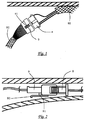
- cables 82, 92 are fixed between the top of the vehicle and a flannelette layer to avoid being exposed outside.
- the cable 82 which is connected to a power source of the vehicle, is connected to the cable 92, which is connected to a rearview mirror, by a connector assembly.
- the connector assembly comprises a male connector 8 and a female connector 9 mated with each other.
- the female connector 9 has a latch 91 extending therefrom.
- the pressing portion 93 of the latch 91 may be compressed by unexpected force to cause the latch 91 of the female connector 9 to be disconnected from the male connector 8, thereby adversely affect an electrical connection between the connectors 8 and 9. Furthermore, due to the vibration of the vehicle, the above-mentioned condition may become even worse and the connectors 8 and 9 are disconnected permanently.
- an electrical connector assembly in accordance with the present invention comprises a first electrical connector and a second electrical connector for matching with the first electrical connector.
- the first electrical connector includes a first dielectric housing, a plurality of first terminals received in the first dielectric housing, a latch extending from the first housing and a retaining device.
- the latch includes a hook portion for locking with the corresponding portion on the second connector and a pressing portion for being exerted on when disconnection the connectors are under expecting.
- the pressing portion and the first dielectric housing define a space therebetween.
- the retaining device includes a main body moveably received in the space.
- FIG. 1 is a side view of a conventional cable connector assembly before assembled onto a top position of a vehicle
- FIG. 2 is a cross-section view of the connector assembly of FIG. 1 after assembled onto the top position of the vehicle;
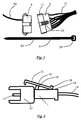
- FIG. 3 is an exploded perspective view of a cable connector assembly in accordance with a first embodiment of the present invention
- FIG. 4 is a side view of a female connector in FIG. 3 before a tie is assembled thereto;
- FIG. 5 is an assembled perspective view of the cable connector assembly in FIG. 3;
- FIG. 6 is a view showing the tie assembled to the female connector of FIG. 5;
- FIG. 7 is a perspective view of the cable connector assembly of FIG. 5 with the tie disassembled therefrom;
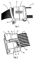
- FIG. 8 is a perspective view of a female connector of a cable connector assembly in accordance with a second embodiment of the present invention.
- FIG. 9 is a view showing a moveable latch sliding through a frame of the female connector.
- FIG. 10 is a perspective view of a female connector of a cable connector assembly in accordance with a third embodiment of the present invention.
- a cable connector assembly in accordance with a first embodiment of the present invention comprises a female connector 1, a male connector 2, a tie 3 and cables 12, 22 respectively connecting with the male and the female connectors 1, 2.
- the tie 3 is made of plastic material and comprises a main portion 31 with serration formed thereon and a locking portion 32 at one end of the main portion 31.
- the tie 3 has a structure substantially the same as the tie used in the art, the detailed description is omitted herein.
- the female connector 1 comprises a dielectric housing 11, and a plurality of terminals 17 received in the housing 11.
- the terminals 17 are electrically connecting with a cable 12.
- the housing 11 has a latch 13 integrally formed on a top thereof.
- the latch 13 includes a.support 16 integrally extending from the housing 11, a hook 15 formed on a front portion of the latch 13 and adapted for latching with a recess (not shown) of the male connector 2, and a pressing portion 14 formed on a rear portion of the latch 13.
- the pressing portion 14 can be pressed downwardly to actuate the hook 15 to separated from the recess of the male connector 2, whereby the female connector 1 can be disconnected from the male connector 2.
- the tie 3 is wrapped around the dielectric housing 11 of the female connector 1 with the main portion 31 extending through the locking portion 32 to secure the tie 3 on the female connector 1.
- the thickness of the main portion 31 is substantially equal to the height of the space between the pressing portion 14 of the latch 13 and a top surface 18 of the dielectric housing 11. Therefore, the main portion 31 of the tie 3 is sandwiched between the pressing portion 14 and the dielectric housing 11.
- a female connector 1' in accordance with a second embodiment of the present invention has a structure substantially the same as the female connector 1 of the first embodiment except that the dielectric housing 11 of the female connector 1' defines a pair of door-shaped frames 5 on a top surface 18 thereof for a moveable block 4 extending therethrough.
- the moveable block 4 includes an elongated main body 41 and a pull tab 42 at one end of the main body 41.
- the main body 41 is formed with a pair of ribs 43 on a top surface thereof.
- the main body 41 of the moveable block 4 passes through the pair of door-shaped frames 5 to be sandwiched between the pressing portion 14 and the dielectric housing 11.
- a thickness of the main body 41 is substantially equal to the height of the space between the pressing portion 14 and a top surface 18 the dielectric housing 11.
- a hole (not labeled) of the frame 5 has a height slightly larger than the thickness of the main body 41 but slightly smaller than the thickness of the ribs 43, whereby the moveable block 4 successfully passes through the frames 5 and is retained below the pressing portion 14 via an interferential engagement between the ribs 43 and the frames 5.
- the moveable block 4 is securely kept in a position below the pressing portion 14 of the latch 13.
- a female connector 1 " in accordance with a third embodiment of the present invention has a structure substantially the same as the female connector 1, 1' of the first and second embodiments except that the dielectric housing 11 of the female connector 1" is formed with a pair of projecting ears 7 on opposite lateral sides (not labeled) thereof.
- a cavity 71 is defined between the projecting ears 7 and a corresponding lateral side of the dielectric housing 11.
- a clip 6 includes a lever 61 and a pair of arms 62 extending forwardly from opposite ends of the lever 61. Each arm 62 is formed with a pair of ribs 63 on a lateral side thereof.
- a thickness of the lever 61 is substantially equal to the height of the space between the pressing portion 14 of the latch 13 and the top surface 18 of the dielectric housing 11.
- the clip 6 is pushed forward to allow the arms 62 to be received in the cavities 71 of the projecting ears 7.
- the pair of ribs 63 of each arm 62 has an interference fit with a corresponding projecting ear 7 to retain the clip 6 to the projecting ear 7.
- the lever 61 is sandwiched between the pressing portion 14 and the top surface 18 of the dielectric housing 11 to prevent the pressing portion 14 from moving downwardly by an unexpected force, thereby ensuring a reliable connection between the female connector 1'' and the male connector 2.
- the two ribs 63 may have different heights, wherein one rib 63 which is adjacent the lever 61 has a height smaller than that of another rib 63, thereby enhancing a reliable engagement between the clip 6 and the projecting ears 7.
Landscapes
- Details Of Connecting Devices For Male And Female Coupling (AREA)
Applications Claiming Priority (4)
| Application Number | Priority Date | Filing Date | Title |
|---|---|---|---|
| CN 03237707 CN2704133Y (zh) | 2003-09-30 | 2003-09-30 | 电缆连接器组合 |
| CN03237707U | 2003-09-30 | ||
| CN 03237708 CN2704134Y (zh) | 2003-09-30 | 2003-09-30 | 电缆连接器 |
| CN03237708U | 2003-09-30 |
Publications (1)
| Publication Number | Publication Date |
|---|---|
| EP1521338A1 true EP1521338A1 (fr) | 2005-04-06 |
Family
ID=34314847
Family Applications (1)
| Application Number | Title | Priority Date | Filing Date |
|---|---|---|---|
| EP04021931A Withdrawn EP1521338A1 (fr) | 2003-09-30 | 2004-09-15 | Assemblage d'un connecteur de câbles |
Country Status (1)
| Country | Link |
|---|---|
| EP (1) | EP1521338A1 (fr) |
Cited By (1)
| Publication number | Priority date | Publication date | Assignee | Title |
|---|---|---|---|---|
| CN112490770A (zh) * | 2020-11-27 | 2021-03-12 | 吴临波 | 一种具有网线保护功能的网线连接用网线插接装置 |
Citations (5)
| Publication number | Priority date | Publication date | Assignee | Title |
|---|---|---|---|---|
| US3828302A (en) * | 1972-09-13 | 1974-08-06 | Bunker Ramo | Electrical connector and mounting means |
| US4708413A (en) * | 1986-03-21 | 1987-11-24 | General Motors Corporation | Electrical connector with position assurance and assist |
| US4938710A (en) * | 1987-12-15 | 1990-07-03 | Honda Giken Kogyo Kabushiki Kaisha | Connector apparatus |
| US4984998A (en) * | 1989-12-15 | 1991-01-15 | Amp Incorporated | High density electrical connector |
| EP0655807A2 (fr) * | 1993-11-30 | 1995-05-31 | The Whitaker Corporation | Dispositif pour assurer la position du connecteur |
-
2004
- 2004-09-15 EP EP04021931A patent/EP1521338A1/fr not_active Withdrawn
Patent Citations (5)
| Publication number | Priority date | Publication date | Assignee | Title |
|---|---|---|---|---|
| US3828302A (en) * | 1972-09-13 | 1974-08-06 | Bunker Ramo | Electrical connector and mounting means |
| US4708413A (en) * | 1986-03-21 | 1987-11-24 | General Motors Corporation | Electrical connector with position assurance and assist |
| US4938710A (en) * | 1987-12-15 | 1990-07-03 | Honda Giken Kogyo Kabushiki Kaisha | Connector apparatus |
| US4984998A (en) * | 1989-12-15 | 1991-01-15 | Amp Incorporated | High density electrical connector |
| EP0655807A2 (fr) * | 1993-11-30 | 1995-05-31 | The Whitaker Corporation | Dispositif pour assurer la position du connecteur |
Cited By (1)
| Publication number | Priority date | Publication date | Assignee | Title |
|---|---|---|---|---|
| CN112490770A (zh) * | 2020-11-27 | 2021-03-12 | 吴临波 | 一种具有网线保护功能的网线连接用网线插接装置 |
Similar Documents
| Publication | Publication Date | Title |
|---|---|---|
| US5775953A (en) | Low-insertion-force connector assembly | |
| JP3364837B2 (ja) | 一体のラッチおよび歪み解放装置を有する電気コネクタ | |
| KR920008315B1 (ko) | 실드 전기 코넥터 | |
| US6179642B1 (en) | Electrical connector assembly having strain-relief | |
| US6027364A (en) | Connector fitting construction with side ribs and corresponding side rib-receiving portions | |
| US6749459B2 (en) | Electrical connection system | |
| US7150634B2 (en) | Connector in which reliable ground connection is assured | |
| US6488524B2 (en) | Half-fitting prevention connector | |
| US6736663B2 (en) | Electrical connector having latching mechanism | |
| US7311546B2 (en) | Connector, a mating connector and a connector device | |
| JPH07302648A (ja) | コネクタのロック結合検知構造 | |
| US20050064756A1 (en) | Cable connector assembly | |
| US5980297A (en) | Lock arm deformation prevention construction | |
| CN110649412B (zh) | 端子金属配件和端子金属配件与壳体的配合结构 | |
| US6966790B2 (en) | Lockable electrical plug and socket connection | |
| US6129565A (en) | Cable connector having a grounding device | |
| US10177487B2 (en) | Electrical connector assembly | |
| JP2006511918A (ja) | フレキシブルケーブル電気コネクタ | |
| JP2001160459A (ja) | 半嵌合防止コネクタ | |
| US20040224563A1 (en) | Electrical connector having contact with pre-pressing structure | |
| JP2001110525A (ja) | コネクタ組立品 | |
| WO2021260627A1 (fr) | Connecteur pour câble plat flexible | |
| JPH11135178A (ja) | コネクタソケット | |
| EP1521338A1 (fr) | Assemblage d'un connecteur de câbles | |
| CN115810949A (zh) | 电连接器 |
Legal Events
| Date | Code | Title | Description |
|---|---|---|---|
| PUAI | Public reference made under article 153(3) epc to a published international application that has entered the european phase |
Free format text: ORIGINAL CODE: 0009012 |
|
| AK | Designated contracting states |
Kind code of ref document: A1 Designated state(s): AT BE BG CH CY CZ DE DK EE ES FI FR GB GR HU IE IT LI LU MC NL PL PT RO SE SI SK TR |
|
| AX | Request for extension of the european patent |
Extension state: AL HR LT LV MK |
|
| AKX | Designation fees paid | ||
| REG | Reference to a national code |
Ref country code: DE Ref legal event code: 8566 |
|
| STAA | Information on the status of an ep patent application or granted ep patent |
Free format text: STATUS: THE APPLICATION IS DEEMED TO BE WITHDRAWN |
|
| 18D | Application deemed to be withdrawn |
Effective date: 20051007 |