EP1521412B1 - Umschalten zwischen Kommunikationsystemen mit Leitungs- und Packetvermittlung - Google Patents
Umschalten zwischen Kommunikationsystemen mit Leitungs- und Packetvermittlung Download PDFInfo
- Publication number
- EP1521412B1 EP1521412B1 EP03022177A EP03022177A EP1521412B1 EP 1521412 B1 EP1521412 B1 EP 1521412B1 EP 03022177 A EP03022177 A EP 03022177A EP 03022177 A EP03022177 A EP 03022177A EP 1521412 B1 EP1521412 B1 EP 1521412B1
- Authority
- EP
- European Patent Office
- Prior art keywords
- call
- video
- audio
- jump
- network
- Prior art date
- Legal status (The legal status is an assumption and is not a legal conclusion. Google has not performed a legal analysis and makes no representation as to the accuracy of the status listed.)
- Expired - Lifetime
Links
- 238000004891 communication Methods 0.000 title description 16
- 230000005236 sound signal Effects 0.000 claims abstract description 14
- 238000000034 method Methods 0.000 claims description 29
- 230000003213 activating effect Effects 0.000 claims description 5
- 230000004044 response Effects 0.000 claims description 4
- 230000004913 activation Effects 0.000 claims description 3
- 230000008878 coupling Effects 0.000 claims description 2
- 238000010168 coupling process Methods 0.000 claims description 2
- 238000005859 coupling reaction Methods 0.000 claims description 2
- 230000000977 initiatory effect Effects 0.000 claims description 2
- 230000009977 dual effect Effects 0.000 claims 2
- 238000010586 diagram Methods 0.000 description 4
- 230000007704 transition Effects 0.000 description 4
- 230000005540 biological transmission Effects 0.000 description 3
- 230000008569 process Effects 0.000 description 3
- 230000006870 function Effects 0.000 description 2
- 230000009191 jumping Effects 0.000 description 2
- 230000009471 action Effects 0.000 description 1
- 230000008901 benefit Effects 0.000 description 1
- 239000000969 carrier Substances 0.000 description 1
- 238000004590 computer program Methods 0.000 description 1
- 230000007246 mechanism Effects 0.000 description 1
- 230000004048 modification Effects 0.000 description 1
- 238000012986 modification Methods 0.000 description 1
- 230000006855 networking Effects 0.000 description 1
- 238000012545 processing Methods 0.000 description 1
- 238000012546 transfer Methods 0.000 description 1
- 230000001960 triggered effect Effects 0.000 description 1
- 238000011144 upstream manufacturing Methods 0.000 description 1
- 230000000007 visual effect Effects 0.000 description 1
Images



Classifications
-
- H—ELECTRICITY
- H04—ELECTRIC COMMUNICATION TECHNIQUE
- H04L—TRANSMISSION OF DIGITAL INFORMATION, e.g. TELEGRAPHIC COMMUNICATION
- H04L12/00—Data switching networks
- H04L12/64—Hybrid switching systems
- H04L12/6418—Hybrid transport
-
- H—ELECTRICITY
- H04—ELECTRIC COMMUNICATION TECHNIQUE
- H04L—TRANSMISSION OF DIGITAL INFORMATION, e.g. TELEGRAPHIC COMMUNICATION
- H04L12/00—Data switching networks
- H04L12/64—Hybrid switching systems
- H04L12/6418—Hybrid transport
- H04L2012/6424—Access arrangements
- H04L2012/6427—Subscriber Access Module; Concentrator; Group equipment
-
- H—ELECTRICITY
- H04—ELECTRIC COMMUNICATION TECHNIQUE
- H04L—TRANSMISSION OF DIGITAL INFORMATION, e.g. TELEGRAPHIC COMMUNICATION
- H04L12/00—Data switching networks
- H04L12/64—Hybrid switching systems
- H04L12/6418—Hybrid transport
- H04L2012/6478—Digital subscriber line, e.g. DSL, ADSL, HDSL, XDSL, VDSL
-
- H—ELECTRICITY
- H04—ELECTRIC COMMUNICATION TECHNIQUE
- H04L—TRANSMISSION OF DIGITAL INFORMATION, e.g. TELEGRAPHIC COMMUNICATION
- H04L12/00—Data switching networks
- H04L12/64—Hybrid switching systems
- H04L12/6418—Hybrid transport
- H04L2012/6483—Video, e.g. MPEG
Definitions
- the invention relates to a call jump and, more particularly, to a call jump system, method and apparatus for jumping an audio call to an audio/video (AV) network, particularly an Internet Protocol Network.
- AV audio/video
- packet oriented communication devices In the field of packet oriented communication devices, what is lacking is the convenience for end users. Unlike in traditional telephone communication where the user simply lifts a hand receiver, packet oriented communication offers a variety of devices with which to access the packet network and to communicate with other users. Problematically, this is inconvenient for the end usr, who must decide which communication form to use when initiating a call.
- PC personal computer
- Video conferencing requires the use of a special video capable device. Thus, the users are required to establish the phone call using the video conferencing device.
- a video conference phone It has been proposed, for example, to use a video conference phone. It has also been proposed to employ a Set Top Box for this purpose, an electronic device that is connected to a communication channel, such as a phone, Integrated Services Digital Network (ISDN) or cable television line, and produces output on a conventional television screen.
- Set-top boxes are commonly used to receive and decode digital television broadcasts and to interface with the Internet through the user's television instead of a PC.
- PSTN Public Switched Telephone Network
- the typical situation is that two parties are already connected through a normal PSTN.
- the question arises how the parties can add video during the PSTN call. It is also not clear how the previous systems would extend their capability to other forms of video information, such as Voice over Internet Protocol (VoIP), as well as other media types.
- VoIP Voice over Internet Protocol
- the question further arises how the parties are able to implement a seamless transition from the PSTN to an environment that supports the video information.
- Burkman et al. (US Patent 5,920,693) filed September 30, 1997, describe an audio to video switchover in video conferencing.
- IP Internet Protocol
- Burkman et al. do not describe how to jump from a standard telephone network to an Internet Protocol (IP) network.
- IP Internet Protocol
- Burkman et al. teach only switching from an audio channel of an Integrated Services Digital Network (ISDN) to a video channel of the ISDN (Col. 4, lines 4-14). For this reason, Burkman et al. nowhere teach a handshaking means for switching between the standard telephone network and the IP network.
- the Burkman et al. solution is thus limited to the ISDN domain and is not able to, therefore, provide the same services as an IP network, such as VoIP and other media types.
- Another difficulty is that of dividing the bandwidth between audio and video information over an IP channel.
- audio suddenly has to share bandwidth with video information it becomes difficult to determine the optimum amount of bandwidth to allocate to each.
- the difficulty presented over an IP line is particularly troublesome.
- a packetized network such as the IP, a significant portion of the bandwidth is dedicated to headers and information describing the identity of the packet and its source and destination.
- What is needed is to allow users to communicate using their known devices, particularly the PSTN telephone, and offer additionally a convenient manner to add video capability.
- What is needed is a device that provides the convenience equipment that the user is accustomed to a such as those found in the common living room. This should be done without inconveniencing the user with a special video conferencing phone. The goal is to seamlessly transition a call to implement the exchange of video information.
- What is needed is a mechanism of the present invention for enabling easy-to-use standard communication equipment which connect through the traditional telephone network that establishes the video communication over an IP connection.
- An objective of the present invention is to allow users to communicate using their known devices.
- An objective of the present invention is to allow users to communicate using the PSTN telephone.
- An objective of the present invention is to offer a convenient manner to add video capability.
- An objective of the present invention is to provide convenient equipment that the user is accustomed to.
- An objective of the present invention is to provide video conferencing using T.V.
- An objective of the present invention is to not inconvenience the user with a special video conferencing phone.
- An objective of the present invention is to seamlessly transition a call to implement the exchange of video information.
- An objective of the present invention is to provide a protocol of for enabling easy-to-use standard communication equipment.
- An objective of the present invention is to connect through the traditional telephone network that establishes the video communication over an IP connection.
- a method for performing a call jump from a call established using a traditional telephone carrier to a video carrying call A traditional telephone call is established with audio signals. It is determined that video should be added to the call. A packetized network is connected to. The audio and video are transmitted over the packetized network.
- a call jump system for jumping a call established over a traditional telephone carrier to a packetized network.
- a video enabled device is capable of rerouting the audio selectively to either the traditional telephone carrier or the packetized network.
- a packetizer packetizes the audio signals from the standard telephone equipment and the video.
- US 2003/0065805 A1 describes a system, method, apparatus and computer program product for providing location based functions and mobile e-commerce. This reference mentions sending a corresponding video signal parallel with the audio signal. However, this is not elegant and requires a significant amount of additional processing. What is required is an elegant way to establish video telephony during a traditional telephone call.
- FIG. 1 there is shown the exemplary system 100, wherein a user 102 initiates a telephone call to another user 104 who is connected to a traditional telephonic network, such as POTS.
- a traditional telephonic network such as POTS.
- the user 104 may be connected to other networks as well.
- the caller 102 initiates an audio call via the standard telephone hand set shown. Normally, the audio call is switched via the POTS switching network through a Digital Line Unit (DLU) 106 coupled to an Electronic Worldwide Switch Digital (EWSD) 108 on the caller side and another EWSD 110 and another DLU 112 on the receiver side of the POTS network as indicated by the arrow 116.
- DLU Digital Line Unit
- EWSD Electronic Worldwide Switch Digital
- a video source such as a set top box 118, which may be coupled to a T.V. 120, for the purpose of capturing the video image of the user 102 at the caller side.
- a video capture device such as a video phone 122 or a video enabled Personal Computer (PC) 124.
- the invention provides a multiplexor 126.
- the telephone output is shown in the figure to be configured through the set top box and then fed into the splitter 128.
- the video information, or data is generated by the video source and shown in the figure to be sent to the multiplexor 126.
- the multiplexor 126 builds, such as packetizing, the data stream for optimal transmission over IP network.
- the set top box 118 of the invention controls the splitter 128.
- the set top box switches the splitter according to either the audio or A/V modes.
- the audio or A/V data is then forwarded to a gateway 130, a network point that acts as an entrance to another network.
- a splitter 132 at the control of the gateway 130, redirects the data stream to either the POTS network 114 or the router 134 of the IP network 136.
- the router 134 determines the next network point to which a packet should be forwarded toward its destination. The router 134 decides which way to send each information packet based on its current understanding of the state of the networks it is connected to.
- a splitter 140 forwards either the packets from the router 138 or, alternatively, the audio data from the POTS network 114.
- Gateway 142 receives either the audio or A/V information from the splitter 140 and forwards the same to the receiving side sub-network where another splitter 144 redirects the audio data to standard telephone equipment 104 or the A/V packets to a demultiplexor 146 that depacketizes the packets.
- the video information is reassembled and displayed by a video display device, such as the T.V. 148 shown.
- Switching control of the IP network may be controlled by a switch, such as the soft switch 150 shown that has control connections the gateways 130 and 142, and the IP network 136.
- the switch is connected as shown in the exemplary figure to the video source 118 which exchanges information, in a protocol such as SIP/NCS/H.323, to indicate to the switch 150 when A/V information is to be transmitted.
- the switch 150 may also be connected to data servers through a suitable protocol, such as SIP or MGCP. These data servers may 152 include conferencing information and applications or MMS applications, for example.
- the switch 150 may be coupled to other networks 154, for example, such as the SS7 network shown. Further, the switch 150 may be connected to other switches 156 through an, for example, an SIP / SIP-T protocol.
- the video capable network may be other than an IP network. It may be, for example, any type of packetized network, such as Ethernet.
- the user 102 initiates an audio call 116.
- the standard telephone equipment generates the audio signals, which are channeled through the set top box 118 and then relayed to the splitter.
- the gateway 130 takes the audio signals and, by control of the splitter 132, redirects the audio signal to the network 114, such as a POTS, where it is handled by the DLUs and EWSD devices.
- the network 114 may be the traditional POTS network, for example.
- the splitter 140 and gateway 142 receive the audio signal and forward the same to the splitter 144 where it is redirected to the telephone equipment of the receiving user 104.
- the video source 118 activates the video capability.
- the video captured of the user 102 is fed back to a display 120 at the user 102 side and optionally displayed.
- the video source directs the video to the multiplexor 126 which packetizes the video signal and the splitter 128 merges the video and audio signals together into a combined real time IP stream.
- the IP stream is transmitted via the gateway 130, the splitter 132 and the router 134 through the IP network 136 as indicated generally by the reference numeral 158.
- the A/V signal is directed by the router 138, the splitter 140, and the gateway 142 and decoded by the splitter 144 and multiplexor 146.
- the audio is parsed and sent to the telephone of the user 104 and the video is directed to the video display 148 for visual display.
- the audio remains transmitted over the standard telephone equipment.
- the video source 118 may be a set top box (STB), which in the context of this application is defined as an electronic device that is connected to a communication channel, such as a phone, Integrated Services Digital Network (ISDN) or cable television line, and produces output on a conventional television screen.
- STB set top box
- the set top box includes the capability to receive and decode digital television broadcasts and to interface with the Internet through the user's television instead of a PC.
- Set-top boxes shall apply not only to the simplest device that receives and unscrambles incoming television signals but also to the more complex that will also function as multimedia desktop computers that can run a variety of advanced services such as video conferencing, home networking, Internet Protocol (IP) telephony, Video on-Demand (VoD) and highspeed Internet TV services.
- IP Internet Protocol
- VoD Video on-Demand
- the invention is also directed to determining an optimal arrangement for transmitting a combine A/V signal through a packetized network.
- dividing the bandwidth between audio and video information over an IP channel is difficult. Audio has to share the bandwidth with video information, and it becomes difficult to determine the optimum amount of bandwidth to allocate.
- a packetized network such as the IP, a significant portion of the bandwidth is dedicated to headers and information describing the identity of the packet and its source and destination.
- the network carriers are constrained, either intentionally to save costs or physically, to narrower bandwidths than that capable. Perhaps, some networks are older than others, such as can occur if the network exists in another country. Further, the up stream and down stream bandwidths are not always symmetrical, meaning that an up link may have a smaller bandwidth than down stream. And, hence the invention takes these factors into account in formulating the optimum IP stream format.
- the bandwidth available shown is approximately 700 Kbps, although the theoretical Kbps is actually much higher.
- the audio and video signals are separated into Time Division Multiplex (TDM) channels.
- the audio is coded according to the G.711 / 723 / 729 protocols and the video according to the H.263 / MPEG-4 protocol.
- the invention could provide an upstream DSL line may provide 768 Kbps for the video signal and the downstream signal may offer 1500 Kbps.
- the invention provides 384 Kbps, for example.
- FIG 3 illustrates a variation 300 on the system shown in Figure 1. Similar features are shown with the same reference numerals.
- the audio call 116 is channeled through the POTS network 114 to the gateway 302, which is coupled to a PSTN 3GPP network 304.
- the network 304 may support mobile phone services, for example.
- a gateway 308 is further provided that is capable of coupling to the 3GPP network 304 such that the A/V stream 158 is coupled to the 3GPP network 304.
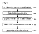
- the invention comprises the steps shown in Figure 4A.
- the video device recognizes an established call, such as from the traditional PSTN network.
- the destination number is stored. It is then recognized in step 406 that video is to be added to the call.
- the existing call is transferred seamlessly to the data network.
- the audio remains transmitted over the standard telephone equipment.
- the A/V data is handled transparent to the user.
- step 410 which represents a variant on the main theme, other media can be added to the call. This may include software related data, such as gaming data for applying on-line games to the A/V signal
- a party A such as the user 102 ( Figure 1) calls party B using a normal or traditional telephone system, such as PSTN, and a normal telephone connection is established according to the known standard telephone call connection procedures.
- the video source (118, Figure 1) on the party A side recognizes and stores the destination phone number in step 502.
- the telephone call acts like a normal call.
- the parties A & B communicate via the standard telephone network using the standard telephone equipment. If it occurs that the parties terminate the call, such as in step 504, the video source 120 takes no action and the destination number is ignored.
- the standard telephone equipment is coupled through the video source 120. As mentioned earlier, the video source 120 forwards the audio signal in this case to the splitter 128.
- the invention triggers the call jump procedure in step 506.
- this is triggered by activation of the user, such as by button or voice activation.
- the button may be, for example, a button already existing with the standard telephone equipment or standard numeric keypad, such as the # key.
- the # key is suitable because it is not normally used during a phone call. Other keys that are not normally used during the call are similarly suitable.
- the corresponding video source recognizes the trigger and initiates the steps necessary for performing the all jump.
- step 510 the video source, for example referenced element 120 ( Figure 1), sends an activating signal to the other end, where another video source may be located. This may be done through the already established POTS telephone call, for example.
- both video enabled devices prepare for the call jump by establishing a connection to the network 136, which is a packetized network in the exemplary embodiment.
- the network 136 is a packetized network in the exemplary embodiment.
- this saves resources on the data network side as the video sources do not have to be online all the time. Thus, it is sufficient to connect on-demand. This is clearly an advantage over to the video communication solutions discussed above, which are reachable only if they are online.
- the video enabled devices each register themselves with the network 136 at a call handling server.
- the video enabled devices send a REGISTER message to an H.323 gatekeeper, a SIP proxy or another call handling server.
- the video enabled devices establish the data call using the known IP network rules for establishing a call, for example. This may be done from either side, but it is exemplary to establish the call from the party A side, so that the original caller may be charged for additional services or added call features.
- the video enabled devices transfer the audio to VoIP.
- the original audio signals are rerouted to the multiplexor in step 518, which packetizes the audio along with the video in step 520, for transmission through the IP network in step 522 via the gateways and routers 130, 134, 138, 142.
- the original audio call 116 is terminated in step 524, which is not necessary, but may save resources and telephone charges.
- the invention provides a seamless jump from a traditional telephone network to a video capable network, such as a packetized network.
- a video capable network such as a packetized network.
- the users are unaware of the jump, other than perhaps a low 'click' caused by the switching.
- the users communicate using their known devices, particularly the PSTN telephone, and offer additionally a convenient manner to add video capability.
- a device that provides the convenience equipment that the user is accustomed to a such as those found in the common living room. This is done without inconveniencing the user with a special video conferencing phone.
- the invention seamlessly transitions a call to implement the exchange of video information.
- a protocol of the present invention for enabling easy-to-use standard communication equipment which connect through the traditional telephone network that establishes the video communication over video enabled carrier, such as an IP connection.
Landscapes
- Engineering & Computer Science (AREA)
- Computer Networks & Wireless Communication (AREA)
- Signal Processing (AREA)
- Telephonic Communication Services (AREA)
- Data Exchanges In Wide-Area Networks (AREA)
- Mobile Radio Communication Systems (AREA)
- Communication Control (AREA)
- Radar Systems Or Details Thereof (AREA)
Claims (19)
- Verfahren zur Implementierung von Videotelefonie von einem Telefonanruf aus, der von einem herkömmlichen Telefonnetzträger verarbeitet wird, mit Hilfe eines Anrufverzweigungsverfahrens (Call Jump), wobei das Verfahren folgende Schritte beinhaltet:Aufbauen (500) eines herkömmlichen Telefonanrufs mit Audiosignalen;Aktivieren (506) der Videotelefonie durch einen der Anrufteilnehmer durch Betätigung eines Telefongerätes oder eines Gerätes, das mit dem Telefongerät auf der Seite dieses Teilnehmers gekoppelt ist, gekennzeichnet durch:Senden eines Aktivierungssignals (510), um das Anrufverzweigungsverfahren in Reaktion auf den das Anrufverzweigungsverfahren initiierenden Aktivierungsschritt an einem Paketierungsnetz abzuschließen, das Videotelefonie unterstützen kann;Akzeptieren (516) einer Anrufverzweigung, die durch das Anrufverzweigungsverfahren initiiert wurde, durch den anderen Anrufteilnehmer und Generieren eines Signals in Reaktion darauf, das anzeigt, dass die Anrufverzweigung abgeschlossen werden sollte;Initiieren der Anrufverzweigung in Reaktion auf das Akzeptieren der Anrufverzweigung, wie dies durch das Signal angezeigt wird, wobei die Teilnehmer über ein paketiertes Netz verbunden werden; undÜbertragen (520) der gemultiplexten Audio- und Videosignale über das paketierte Netz;Beenden (524) des Telefonanrufs über den herkömmlichen Telefonnetzträger, wobei die durch die Anrufverzweigung aufgebaute Videotelefonie weiter fortgesetzt werden kann.
- Verfahren nach jedem der vorstehenden Ansprüche, das weiterhin den Schritt des Paketierens (520) der Audiosignale und der Videosignale beinhaltet.
- Verfahren nach jedem der vorstehenden Ansprüche, das weiterhin den Schritt des Bestimmens einer optimalen Aufteilung zwischen Audio- und Videobandbreite durch Multiplexen der Videosignale mit den Audiosignalen nach Bedarf beinhaltet.
- Verfahren nach jedem der vorstehenden Ansprüche, das weiterhin den Schritt des Erkennens eines aufgebauten Anrufs durch das Videogerät beinhaltet.
- Verfahren nach jedem der vorstehenden Ansprüche, das weiterhin den Schritt des Speicherns der Zielnummer beinhaltet.
- Verfahren nach jedem der vorstehenden Ansprüche, das weiterhin den Schritt des Erkennens (502), dass der Anruf um Videofunktionalität erweitert werden soll, beinhaltet.
- Verfahren nach jedem der vorstehenden Ansprüche, das weiterhin den Schritt des Aufbauens einer Verbindung (512) durch videofähige Geräte beinhaltet.
- Verfahren nach jedem der vorstehenden Ansprüche, das weiterhin den Schritt des Registrierens (514) der videofähigen Geräte beinhaltet.
- System (300) für die Implementierung von Videotelefonie von einem Telefonanruf aus, der von einem herkömmlichen Telefonnetzträger (114) verarbeitet wird, mit Hilfe eines Anrufverzweigungsverfahrens (Call Jump), wobei das System Folgendes beinhaltet:ein Mittel (102, 306) zum Eingeben der Entscheidung eines Teilnehmers, die Videotelefonie während des herkömmlichen Telefonanrufs auf der Seite des Anrufteilnehmers zu aktivieren;ein Mittel (118) zum Senden eines Aktivierungssignals, das das Anrufsverzweigungsverfahren initiiert, das durch die andere Teilnehmerseite abgeschlossen werden muss, um eine Anrufverzweigung zu einem paketierten Netz aufzubauen, das Videotelefonie unterstützen kann;ein Mittel (150) zum Akzeptieren der durch die Anrufverzweigungsprozedur aufgebauten Anrufverzweigung durch den anderen Teilnehmer;ein videofähiges Gerät (118), das das Audiosignal selektiv entweder zum herkömmlichen Telefonnetzträger oder zum paketierten Netz umleiten kann;ein Multiplexer (150) zum Multiplexen der Audio- und Videosignale; undein Paketierer (118) zum Paketieren der von der Standardtelefonausrüstung kommenden gemultiplexten Audio- und Videosignale und der Videosignale, die über das paketierte Netz gesendet werden sollen, wenn die Anrufverzweigung vom einen Teilnehmer gewünscht und vom anderen Teilnehmer akzeptiert wird;Beenden des über den herkömmlichen Telefonnetzträger (114) geführten Telefonanrufs durch den herkömmlichen Telefonnetzträger und Zulassen der Fortsetzung der durch die Anrufverzweigung aufgebauten Videotelefonie.
- System nach Anspruch 9, das weiterhin ein Gateway-Mittel (130, 142) zum Koppeln der paketierten Audio- und Videosignale entweder an den herkömmlichen Telefonnetzträger oder das paketierte Netz beinhaltet.
- System nach jedem der vorstehenden Ansprüche 9 - 10, das weiterhin einen Router (134, 138) zum Routen der paketierten Audio- und Videosignale durch das paketierte Netz zu einer Empfängerseite beinhaltet.
- System nach jedem der vorstehenden Ansprüche 9 - 11, bei dem das videofähige Gerät eine Set-Top-Box (118) ist.
- System nach jedem der vorstehenden Ansprüche 9 - 12, bei dem das videofähige Gerät ein Videotelefon (122) ist.
- System nach jedem der vorstehenden Ansprüche 9 - 13, bei dem das videofähige Gerät ein videofähiger PC (124) ist.
- System nach jedem der vorstehenden Ansprüche 9 - 14, bei dem das paketierte Netz ein IP-Netz (136) ist.
- Verfahren nach Anspruch 1, bei dem der Schritt des Aktivierens durch Betätigung mindestens einer MFV-Taste am Telefongerät (102) durchgeführt wird.
- Verfahren nach Anspruch 1, das weiterhin den Schritt der Belastung des Teilnehmers mit den Gebühren beinhaltet, der die Anrufverzweigung aktiviert.
- System nach Anspruch 9, das weiterhin mindestens eine MFV-Taste zur Aktivierung der Anrufverzweigung beinhaltet.
- System nach Anspruch 9, das weiterhin ein Mittel zur Belastung des Teilnehmers mit den Gebühren beinhaltet, der die Anrufverzweigung aktiviert.
Priority Applications (9)
| Application Number | Priority Date | Filing Date | Title |
|---|---|---|---|
| DE60312332T DE60312332T2 (de) | 2003-09-30 | 2003-09-30 | Anrufsprungsystem, verfahren und vorrichtung |
| EP03022177A EP1521412B1 (de) | 2003-09-30 | 2003-09-30 | Umschalten zwischen Kommunikationsystemen mit Leitungs- und Packetvermittlung |
| CNA2004800283715A CN1961546A (zh) | 2003-09-30 | 2004-09-28 | 具有电路和分组交换的通信系统之间的交换 |
| EP04787235A EP1668852B1 (de) | 2003-09-30 | 2004-09-28 | Anrufsprung zwischen kommunikationssystemen bei verwendung eines sprungs zwischen einem leitungsvermittelten und einem paketvermittelten system |
| US10/574,335 US7773544B2 (en) | 2003-09-30 | 2004-09-28 | Call jump system, method and apparatus |
| JP2006530256A JP2007507939A (ja) | 2003-09-30 | 2004-09-28 | 回線交換およびパケット交換による通信システム間の交換 |
| PCT/EP2004/052339 WO2005032081A1 (en) | 2003-09-30 | 2004-09-28 | A call jump system, method & apparatus |
| DE602004017760T DE602004017760D1 (de) | 2003-09-30 | 2004-09-28 | Anrufsprung zwischen kommunikationssystemen bei verwendung eines sprungs zwischen einem leitungsvermittelten und einem paketvermittelten system |
| AT04787235T ATE414371T1 (de) | 2003-09-30 | 2004-09-28 | Anrufsprung zwischen kommunikationssystemen bei verwendung eines sprungs zwischen einem leitungsvermittelten und einem paketvermittelten system |
Applications Claiming Priority (1)
| Application Number | Priority Date | Filing Date | Title |
|---|---|---|---|
| EP03022177A EP1521412B1 (de) | 2003-09-30 | 2003-09-30 | Umschalten zwischen Kommunikationsystemen mit Leitungs- und Packetvermittlung |
Publications (2)
| Publication Number | Publication Date |
|---|---|
| EP1521412A1 EP1521412A1 (de) | 2005-04-06 |
| EP1521412B1 true EP1521412B1 (de) | 2007-03-07 |
Family
ID=34306813
Family Applications (2)
| Application Number | Title | Priority Date | Filing Date |
|---|---|---|---|
| EP03022177A Expired - Lifetime EP1521412B1 (de) | 2003-09-30 | 2003-09-30 | Umschalten zwischen Kommunikationsystemen mit Leitungs- und Packetvermittlung |
| EP04787235A Expired - Lifetime EP1668852B1 (de) | 2003-09-30 | 2004-09-28 | Anrufsprung zwischen kommunikationssystemen bei verwendung eines sprungs zwischen einem leitungsvermittelten und einem paketvermittelten system |
Family Applications After (1)
| Application Number | Title | Priority Date | Filing Date |
|---|---|---|---|
| EP04787235A Expired - Lifetime EP1668852B1 (de) | 2003-09-30 | 2004-09-28 | Anrufsprung zwischen kommunikationssystemen bei verwendung eines sprungs zwischen einem leitungsvermittelten und einem paketvermittelten system |
Country Status (7)
| Country | Link |
|---|---|
| US (1) | US7773544B2 (de) |
| EP (2) | EP1521412B1 (de) |
| JP (1) | JP2007507939A (de) |
| CN (1) | CN1961546A (de) |
| AT (1) | ATE414371T1 (de) |
| DE (2) | DE60312332T2 (de) |
| WO (1) | WO2005032081A1 (de) |
Families Citing this family (11)
| Publication number | Priority date | Publication date | Assignee | Title |
|---|---|---|---|---|
| US20060002373A1 (en) * | 2004-06-30 | 2006-01-05 | Michael Denny | Terminals, methods, systems, and computer program products for providing video communications over a broadband connection based on a call via a PSTN |
| US20060090166A1 (en) * | 2004-09-30 | 2006-04-27 | Krishna Dhara | System and method for generating applications for communication devices using a markup language |
| US8488591B2 (en) * | 2004-12-23 | 2013-07-16 | Telecom Italia S.P.A. | Method and system for video telephone communications set up, related equipment and computer program product |
| KR100895425B1 (ko) * | 2007-04-19 | 2009-05-07 | (주)제너시스템즈 | 일체형 영상 폰 사용 환경에서 영상전화를 제공하는 방법및 시스템 |
| US8619759B2 (en) * | 2007-06-15 | 2013-12-31 | At&T Intellectual Property I, Lp | System for video call processing |
| US8340268B2 (en) * | 2008-05-14 | 2012-12-25 | Polycom, Inc. | Method and system for providing a user interface to a portable communication device for controlling a conferencing session |
| US8725880B2 (en) | 2010-04-07 | 2014-05-13 | Apple, Inc. | Establishing online communication sessions between client computing devices |
| US8964544B2 (en) * | 2010-10-14 | 2015-02-24 | T-Mobile Usa, Inc. | Quality of service adjustments to improve network utilization |
| JP5877351B2 (ja) * | 2010-12-15 | 2016-03-08 | パナソニックIpマネジメント株式会社 | 通信装置および通信方法 |
| US20120275450A1 (en) | 2011-04-29 | 2012-11-01 | Comcast Cable Communications, Llc | Obtaining Services Through a Local Network |
| US9866700B2 (en) * | 2012-12-27 | 2018-01-09 | Robert Bosch Gmbh | Conference system and process for voice activation in the conference system |
Family Cites Families (10)
| Publication number | Priority date | Publication date | Assignee | Title |
|---|---|---|---|---|
| JPS57159153A (en) | 1981-03-25 | 1982-10-01 | Nippon Telegr & Teleph Corp <Ntt> | Line-packet selection communicating system |
| US6215515B1 (en) * | 1992-02-19 | 2001-04-10 | Netergy Networks, Inc. | Videocommunicating device with an on-screen telephone keypad user-interface method and arrangement |
| JPH05304541A (ja) | 1992-04-27 | 1993-11-16 | Fujitsu Ltd | 端末装置 |
| AU1465997A (en) * | 1995-12-21 | 1997-07-14 | Intel Corporation | Method and apparatus for integrating video, voice and computer data traffic in a single, conferencing system using existing telephone and catv connections |
| US6199047B1 (en) * | 1997-12-31 | 2001-03-06 | Csg Systems, Inc. | Apparatus and method for an event rating engine |
| AU2001247856A1 (en) * | 2000-03-29 | 2001-10-08 | Openwave Technologies Inc. | System and method for streaming internet audio and video to a wireless telephone |
| US7487112B2 (en) * | 2000-06-29 | 2009-02-03 | Barnes Jr Melvin L | System, method, and computer program product for providing location based services and mobile e-commerce |
| US6891841B2 (en) * | 2001-03-12 | 2005-05-10 | Advent Networks, Inc. | Time division multiple access over broadband modulation method and apparatus |
| JP3896873B2 (ja) | 2002-03-07 | 2007-03-22 | 日本電気株式会社 | 可変通信システム |
| US7489671B2 (en) * | 2003-02-14 | 2009-02-10 | Marsico Robert G | Telephone management system and method |
-
2003
- 2003-09-30 EP EP03022177A patent/EP1521412B1/de not_active Expired - Lifetime
- 2003-09-30 DE DE60312332T patent/DE60312332T2/de not_active Expired - Fee Related
-
2004
- 2004-09-28 EP EP04787235A patent/EP1668852B1/de not_active Expired - Lifetime
- 2004-09-28 CN CNA2004800283715A patent/CN1961546A/zh active Pending
- 2004-09-28 US US10/574,335 patent/US7773544B2/en active Active
- 2004-09-28 WO PCT/EP2004/052339 patent/WO2005032081A1/en not_active Ceased
- 2004-09-28 DE DE602004017760T patent/DE602004017760D1/de not_active Expired - Lifetime
- 2004-09-28 AT AT04787235T patent/ATE414371T1/de not_active IP Right Cessation
- 2004-09-28 JP JP2006530256A patent/JP2007507939A/ja active Pending
Also Published As
| Publication number | Publication date |
|---|---|
| ATE414371T1 (de) | 2008-11-15 |
| CN1961546A (zh) | 2007-05-09 |
| DE602004017760D1 (de) | 2008-12-24 |
| EP1521412A1 (de) | 2005-04-06 |
| WO2005032081A1 (en) | 2005-04-07 |
| JP2007507939A (ja) | 2007-03-29 |
| DE60312332T2 (de) | 2008-01-10 |
| US7773544B2 (en) | 2010-08-10 |
| DE60312332D1 (de) | 2007-04-19 |
| US20080037513A1 (en) | 2008-02-14 |
| EP1668852A1 (de) | 2006-06-14 |
| EP1668852B1 (de) | 2008-11-12 |
Similar Documents
| Publication | Publication Date | Title |
|---|---|---|
| US6768722B1 (en) | Systems and methods for managing multiple communications | |
| US6681252B1 (en) | System and method for interconnecting portable information devices through a network based telecommunication system | |
| US6870830B1 (en) | System and method for performing messaging services using a data communications channel in a data network telephone system | |
| US6262978B1 (en) | Call completion of video telephone/teleconference call as packet voice call | |
| US6741586B1 (en) | System and method for sharing computer screens over a telephony network | |
| AU730598B2 (en) | A telephone doubler arrangement | |
| US20030002476A1 (en) | Integrated internet phone call routing system | |
| US20050009519A1 (en) | Communication apparatus and operation control method therefor | |
| EP1685699A2 (de) | Videorelaissystem und verfahren | |
| US6707797B1 (en) | Multi-line telephony via network gateways | |
| EP1668852B1 (de) | Anrufsprung zwischen kommunikationssystemen bei verwendung eines sprungs zwischen einem leitungsvermittelten und einem paketvermittelten system | |
| US7567269B2 (en) | Television phone adaptor | |
| CN1302139A (zh) | Ip租用线路 | |
| US7460523B2 (en) | Client-server architecture for the delivery of broadband services | |
| US8611522B2 (en) | Telephone call processing method and apparatus | |
| US20090238176A1 (en) | Method, telephone system and telephone terminal for call session | |
| JP4391362B2 (ja) | 画像通信装置 | |
| US20030048772A1 (en) | System for converting GR303 signals to NCS signals | |
| KR100799478B1 (ko) | VoIP 시스템용 비디오 어댑터 장치 및 이를 이용한영상통화 서비스 제공방법 | |
| KR100474070B1 (ko) | 디스플레이 장착형 전화기를 이용한 전화 채팅 서비스제공방법 | |
| KR100330140B1 (ko) | 인터넷폰 시스템 | |
| KR20040095094A (ko) | 전화와 PC를 연동한 VoIP 화상 전화 서비스 방법 | |
| Chowdhury | Voice over IP | |
| KR20060133280A (ko) | 집합형 VoIP 장비를 이용한 VoIP 서비스 제공시스템 및 방법 |
Legal Events
| Date | Code | Title | Description |
|---|---|---|---|
| PUAI | Public reference made under article 153(3) epc to a published international application that has entered the european phase |
Free format text: ORIGINAL CODE: 0009012 |
|
| AK | Designated contracting states |
Kind code of ref document: A1 Designated state(s): AT BE BG CH CY CZ DE DK EE ES FI FR GB GR HU IE IT LI LU MC NL PT RO SE SI SK TR |
|
| AX | Request for extension of the european patent |
Extension state: AL LT LV MK |
|
| 17P | Request for examination filed |
Effective date: 20051006 |
|
| AKX | Designation fees paid |
Designated state(s): DE FR GB |
|
| GRAP | Despatch of communication of intention to grant a patent |
Free format text: ORIGINAL CODE: EPIDOSNIGR1 |
|
| RIN1 | Information on inventor provided before grant (corrected) |
Inventor name: HNYK, RUEDIGER Inventor name: GRANZER, HERMANN, DR. |
|
| GRAS | Grant fee paid |
Free format text: ORIGINAL CODE: EPIDOSNIGR3 |
|
| GRAA | (expected) grant |
Free format text: ORIGINAL CODE: 0009210 |
|
| AK | Designated contracting states |
Kind code of ref document: B1 Designated state(s): DE FR GB |
|
| REG | Reference to a national code |
Ref country code: GB Ref legal event code: FG4D |
|
| REF | Corresponds to: |
Ref document number: 60312332 Country of ref document: DE Date of ref document: 20070419 Kind code of ref document: P |
|
| ET | Fr: translation filed | ||
| PLBE | No opposition filed within time limit |
Free format text: ORIGINAL CODE: 0009261 |
|
| STAA | Information on the status of an ep patent application or granted ep patent |
Free format text: STATUS: NO OPPOSITION FILED WITHIN TIME LIMIT |
|
| 26N | No opposition filed |
Effective date: 20071210 |
|
| PGFP | Annual fee paid to national office [announced via postgrant information from national office to epo] |
Ref country code: FR Payment date: 20080912 Year of fee payment: 6 |
|
| REG | Reference to a national code |
Ref country code: FR Ref legal event code: TP |
|
| PGFP | Annual fee paid to national office [announced via postgrant information from national office to epo] |
Ref country code: DE Payment date: 20080919 Year of fee payment: 6 |
|
| REG | Reference to a national code |
Ref country code: FR Ref legal event code: ST Effective date: 20100531 |
|
| PG25 | Lapsed in a contracting state [announced via postgrant information from national office to epo] |
Ref country code: FR Free format text: LAPSE BECAUSE OF NON-PAYMENT OF DUE FEES Effective date: 20090930 Ref country code: DE Free format text: LAPSE BECAUSE OF NON-PAYMENT OF DUE FEES Effective date: 20100401 |
|
| PGFP | Annual fee paid to national office [announced via postgrant information from national office to epo] |
Ref country code: GB Payment date: 20220927 Year of fee payment: 20 |
|
| REG | Reference to a national code |
Ref country code: GB Ref legal event code: PE20 Expiry date: 20230929 |
|
| PG25 | Lapsed in a contracting state [announced via postgrant information from national office to epo] |
Ref country code: GB Free format text: LAPSE BECAUSE OF EXPIRATION OF PROTECTION Effective date: 20230929 |