EP1521456A2 - Bildaufnahmevorrichtung, Bildanzeigeverfahren und Programm - Google Patents
Bildaufnahmevorrichtung, Bildanzeigeverfahren und Programm Download PDFInfo
- Publication number
- EP1521456A2 EP1521456A2 EP04255965A EP04255965A EP1521456A2 EP 1521456 A2 EP1521456 A2 EP 1521456A2 EP 04255965 A EP04255965 A EP 04255965A EP 04255965 A EP04255965 A EP 04255965A EP 1521456 A2 EP1521456 A2 EP 1521456A2
- Authority
- EP
- European Patent Office
- Prior art keywords
- image
- display device
- image capture
- display
- capture apparatus
- Prior art date
- Legal status (The legal status is an assumption and is not a legal conclusion. Google has not performed a legal analysis and makes no representation as to the accuracy of the status listed.)
- Granted
Links
Images


Classifications
-
- H—ELECTRICITY
- H04—ELECTRIC COMMUNICATION TECHNIQUE
- H04N—PICTORIAL COMMUNICATION, e.g. TELEVISION
- H04N23/00—Cameras or camera modules comprising electronic image sensors; Control thereof
- H04N23/60—Control of cameras or camera modules
- H04N23/63—Control of cameras or camera modules by using electronic viewfinders
- H04N23/631—Graphical user interfaces [GUI] specially adapted for controlling image capture or setting capture parameters
-
- H—ELECTRICITY
- H04—ELECTRIC COMMUNICATION TECHNIQUE
- H04N—PICTORIAL COMMUNICATION, e.g. TELEVISION
- H04N23/00—Cameras or camera modules comprising electronic image sensors; Control thereof
- H04N23/50—Constructional details
- H04N23/53—Constructional details of electronic viewfinders, e.g. rotatable or detachable
- H04N23/531—Constructional details of electronic viewfinders, e.g. rotatable or detachable being rotatable or detachable
-
- H—ELECTRICITY
- H04—ELECTRIC COMMUNICATION TECHNIQUE
- H04N—PICTORIAL COMMUNICATION, e.g. TELEVISION
- H04N23/00—Cameras or camera modules comprising electronic image sensors; Control thereof
- H04N23/60—Control of cameras or camera modules
- H04N23/66—Remote control of cameras or camera parts, e.g. by remote control devices
Definitions
- the present invention relates to an image capture apparatus, and more specifically to an image capture apparatus capable of capturing images in normal and self-portrait shooting modes.
- the image-capture section includes a camera lens for use in photo-taking a subject.
- the display section includes a monitor screen to display thereon an image captured by the image-capture section or an image reproduced from a recording medium.
- Some digital cameras have the display section coupled to the image-capture section via a joint portion such that the display section is rotatable with respect to the image-capture section. These digital cameras allow for both normal shooting and self-portrait shooting. In normal shooting, the direction in which the camera lens faces is opposite to the direction in which the monitor screen faces. In self-portrait shooting in which the photographer can photograph himself, the direction of the camera lens faces in the same direction as the monitor screen.
- an indication member such as an LED, for indicating the focusing state of the digital camera is one of the above-described indication members.
- the image capture apparatus includes an image capture device operable to capture the image and output an image signal corresponding to the captured image; a display device operable to display a displayed image; a reversing device generating a mirror image of the captured image from the image signal; and a controller controlling the display device to display the displayed image.
- the image capture apparatus is capable of preventing a user from operating an operation member that may cause a problem if operated when the monitor screen is in the self-portrait shooting posture.
- the image capture apparatus includes an inhibition device inhibiting operation of the operation device by the user responsive to the display device being in the second position.
- Fig. 1 is a block diagram showing the components of an image capture apparatus according to an exemplary embodiment of the invention.
- Fig. 4 is a view as seen from the front of the image capture apparatus, showing the self-portrait shooting mode in which the monitor faces in the same direction as a photo-taking lens.
- Fig. 6 is a flow chart illustrating the sequence of image data transfer during the normal shooting mode performed by a memory control circuit in a rectangular area on the DRAM shown in Fig. 5A.
- Fig. 8 is a flow chart illustrating the sequence of image erasure and menu display processing executed by a CPU depending on the operating conditions of a switch group.
- the image capture apparatus further includes an on-screen display (hereinafter referred to as "OSD") circuit 116.
- the OSD circuit 116 outputs a character signal corresponding to character data transmitted from the CPU 100.
- the image capture apparatus further includes a switch group 122.
- the switch group 122 includes a switch SF1, a switch SF2, a switch SF3, a switch SF4, etc..., which are connected to the CPU 100.
- the image capture apparatus further includes an LED indication circuit 125.
- the LED indication circuit 125 is provided for turning on LEDs (light emitting diodes) to give notice or warning, and includes an LED 126 and an LED 127, which are further described later with reference to Fig. 2.
- the details of the switch group 122 are described as follows.
- the switch SF3 is a menu switch for switching settings of the image capture apparatus. In response to the switch SF3 being turned on by the photographer, the image capture apparatus comes into a mode allowing the photographer to switch settings of the image capture apparatus.
- the switch SF4 is an erase switch for erasing image data. In response to the switch SF4 being turned on by the photographer, captured image data is erased.
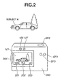
- a shutter speed (1/250) 201, an aperture value (F5.6) 202 and a remaining number of recordable frames (50) 203 which are parameters used for capturing a still image, are displayed while being superimposed on a photo-taken subject image.
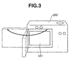
- Fig. 3 is a view as seen from the back side of the image capture apparatus, showing the state where the monitor 121 is rotatable around the joint portion 204 with respect the camera section 200.
- Fig. 4 is a view as seen from the front of the image capture apparatus, showing the self-portrait shooting mode in which the monitor 121 faces in the same direction as the photo-taking lens 106.
- the image capture apparatus comes into the self-portrait shooting mode.
- the scanning direction on an image plane of the monitor 121 is made opposite to that described in Fig. 2, so that a video image of a subject B is displayed on the monitor 121 as a mirror image in which an original image is horizontally reversed.
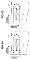
- the memory control circuit 115 regards the DRAM 104 as a two-dimensional plane and performs data transfer (writing of image data) to a rectangular area on the DRAM 104.
- Fig. 5A illustrates image data transfer performed when the image capture apparatus is in the normal shooting mode.
- points P1, P2, P3, P4, P5 and P6 denote addresses.
- Reference character N denotes the number of lines in the rectangular area to which data is transferred.
- Reference character M denotes the number of pixels (the number of words) of one line. Values of all distances (offsets) J indicated by broken lines are the same, each being equal to "P3 - P2".
- Data transfer to the rectangular area is effected by sequentially writing image data for M words from each of the leftmost addresses P1, P2, P3, ... P4 toward increased addresses over N times from the top line to the bottom line.
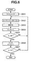
- Fig. 6 is a flow chart illustrating the sequence of image data transfer during the normal shooting mode performed by the memory control circuit 115 in the rectangular area on the DRAM 104 shown in Fig. 5A. It should be noted that values P1, M, N and J shown in Fig. 6 correspond respectively to the address P1, the number M of pixels, the number N of lines and the distance J shown in Fig. 5A. These values are previously set at setting registers of the memory control circuit 115.
- the memory control circuit 115 writes image data to an area on the DRAM 104 designated by the address "a" computed at step S602.
- step S605 if it is determined at step S605 that the counter value "h” is not equal to the number M of pixels, or if it is determined at step S607 that the counter value "c" is not equal to the number N of lines, the flow returns to step S602.
- step S615 determines whether the counter value "h" is equal to the number M of pixels, or if it is determined at step S617 that the counter value "c" is not equal to the number N of lines.
- the variable magnification circuit 111 performs sub-sampling, linear interpolation processing, etc..., of pixel data of a captured image in accordance with the display size of the monitor 121. In particular, the variable magnification circuit 111 reduces the size of image data supplied from the signal processing circuit 110 both in the horizontal direction and the vertical direction to output overall-reduced image data to the memory control circuit 115.
- the CPU 100 causes the memory control circuit 115 to effect processing of the sequence shown in Fig. 6 when the monitor 121 is in the normal shooting posture shown in Fig. 2.
- the memory control circuit 115 sequentially writes, to addresses "a" on the DRAM 104, image data according with the display size supplied from the variable magnification circuit 111. Accordingly, overall-reduced image data are written into the DRAM 104, as shown in Fig. 5A.
- the memory control circuit 115 sequentially reads out the overall-reduced image data stored in the DRAM 104 from the leftmost address to the rightmost address and from the top line to the bottom line on the two-dimensional plane of the DRAM 104 (the same scanning direction as the writing action shown in Fig. 5A). Then, the memory control circuit 115 outputs the read-out image data to the reproduction circuit 120.
- step S701 if it is determined at step S701 that the image capture apparatus is in the normal shooting mode, the flow proceeds to step S702.
- step S702 the CPU 100 makes a check to determine whether the erase switch SF4 is turned on. If it is determined that the erase switch SF4 is turned on, the flow proceeds to step S703.
- step S703 the CPU 100 executes processing for erasing image data that has been last recorded. Then, the CPU 100 brings the flow to an end.
- step S704 the flow proceeds to step S704.
- step S704 the CPU 100 makes a check to determine whether the menu switch SF3 is turned on. If it is determined that the menu switch SF3 is turned on, the flow proceeds to step S705.
- step S705 the CPU 100 causes the monitor 121 to display a menu. The photographer, when viewing the menu displayed on the monitor 121, may give the image capture apparatus instructions to change settings thereof. After completion of processing for changing the settings of the image capture apparatus, the CPU 100 brings the flow to an end.
- processing for generating a mirror image of the photo-taken image processing for generating a character information pattern and processing for displaying the OSD lighting indications 401 and 402 shown in Fig. 4 can also be effected at the timing of the step S706.
- a character information pattern in such an orientation as to make the character information pattern normally recognizable on the monitor screen can be superimposed on a mirror image of the captured image displayed on the monitor screen, without need for an increase in circuitry scale.
- a content to be displayed by a display member which is located on the back side of the image capture apparatus and which cannot be viewed by a photographer when a monitor section is in the self-portrait shooting posture is displayed on the monitor section in a superimposed fashion during the self-portrait shooting mode. Accordingly, the photographer can notice the above content even during the self-portrait shooting mode.
- the present invention can also be achieved by providing a system or apparatus with a storage medium that stores a program code of software for realizing the functions of the above-described embodiment, and causing a computer (or a CPU, MPU or the like) of the system or apparatus to read the program code from the storage medium and then to execute the program code.
- the program code itself read from the storage medium realizes the novel functions of the embodiment, and a storage medium storing the program code and a program containing the program code each constitute the invention.
- the storage medium for providing the program code includes a flexible disk, a hard disk, an optical disk, a magneto-optical disk, a CD-ROM, a CD-R, a CD-RW, a DVD-ROM, a DVD-RAM, a DVD-RW, a DVD-R, a magnetic tape, a non-volatile memory card, a ROM, etc...
- the present invention includes an OS (operating system) or the like running on the computer performing an actual process in whole or in part according to instructions of the program code to realize the functions of the above-described embodiment.
- OS operating system
- the present invention also includes a CPU or the like contained in a function expansion board inserted into the computer or in a function expansion unit connected to the computer, the function expansion board or the function expansion unit having a memory in which the program code read from the storage medium is written, the CPU or the like performing an actual process in whole or in part according to instructions of the program code to realize the functions of the above-described embodiment.
Landscapes
- Engineering & Computer Science (AREA)
- Multimedia (AREA)
- Signal Processing (AREA)
- Human Computer Interaction (AREA)
- Studio Devices (AREA)
- Studio Circuits (AREA)
- Controls And Circuits For Display Device (AREA)
Applications Claiming Priority (2)
| Application Number | Priority Date | Filing Date | Title |
|---|---|---|---|
| JP2003343722 | 2003-10-01 | ||
| JP2003343722A JP4174404B2 (ja) | 2003-10-01 | 2003-10-01 | 撮像装置、画像表示方法、プログラムおよび記憶媒体 |
Publications (3)
| Publication Number | Publication Date |
|---|---|
| EP1521456A2 true EP1521456A2 (de) | 2005-04-06 |
| EP1521456A3 EP1521456A3 (de) | 2007-08-22 |
| EP1521456B1 EP1521456B1 (de) | 2016-05-18 |
Family
ID=34309123
Family Applications (1)
| Application Number | Title | Priority Date | Filing Date |
|---|---|---|---|
| EP04255965.8A Expired - Lifetime EP1521456B1 (de) | 2003-10-01 | 2004-09-29 | Bildaufnahmevorrichtung, Bildanzeigeverfahren und Programm |
Country Status (4)
| Country | Link |
|---|---|
| US (2) | US7414657B2 (de) |
| EP (1) | EP1521456B1 (de) |
| JP (1) | JP4174404B2 (de) |
| CN (1) | CN100369461C (de) |
Cited By (1)
| Publication number | Priority date | Publication date | Assignee | Title |
|---|---|---|---|---|
| RU2643352C2 (ru) * | 2012-04-25 | 2018-02-01 | Сони Корпорейшн | Устройство управления отображением и способ управления отображением |
Families Citing this family (28)
| Publication number | Priority date | Publication date | Assignee | Title |
|---|---|---|---|---|
| US7733405B2 (en) * | 2005-02-10 | 2010-06-08 | Seiko Epson Corporation | Apparatus and method for resizing an image |
| JP2006279307A (ja) * | 2005-03-28 | 2006-10-12 | Toshiba Corp | 画像記録再生装置及びキーアサイン変更方法 |
| KR100677237B1 (ko) * | 2005-05-03 | 2007-02-02 | 엘지전자 주식회사 | 듀얼 엘시디를 구비한 영상 표시장치 |
| JP2006324731A (ja) * | 2005-05-17 | 2006-11-30 | Matsushita Electric Ind Co Ltd | 映像信号処理回路 |
| JP2007013768A (ja) * | 2005-07-01 | 2007-01-18 | Konica Minolta Photo Imaging Inc | 撮像装置 |
| US20100066895A1 (en) * | 2005-12-06 | 2010-03-18 | Panasonic Corporation | Digital camera |
| CN101715061B (zh) | 2005-12-06 | 2012-07-04 | 松下电器产业株式会社 | 数字相机、相机机身及该数字相机的控制方法 |
| US20100066890A1 (en) * | 2005-12-06 | 2010-03-18 | Panasonic Corporation | Digital camera |
| US8223242B2 (en) * | 2005-12-06 | 2012-07-17 | Panasonic Corporation | Digital camera which switches the displays of images with respect to a plurality of display portions |
| US7918614B2 (en) * | 2006-01-20 | 2011-04-05 | Sony Ericsson Mobile Communications Ab | Camera for electronic device |
| CN101571620B (zh) * | 2008-04-30 | 2011-11-02 | 联想(北京)有限公司 | 调节摄像单元的方法和设备 |
| US20110210970A1 (en) * | 2008-06-18 | 2011-09-01 | Kazu Segawa | Digital mirror apparatus |
| JP5213585B2 (ja) | 2008-08-22 | 2013-06-19 | キヤノン株式会社 | 画像処理装置およびその制御方法 |
| JP2010273021A (ja) * | 2009-05-20 | 2010-12-02 | Sony Corp | 画像表示装置、画像表示方法 |
| CA2798246C (en) | 2010-05-03 | 2023-09-12 | Creatv Microtech, Inc. | Polymer microfilters and methods of manufacturing the same |
| US11175279B2 (en) | 2010-05-03 | 2021-11-16 | Creatv Microtech, Inc. | Polymer microfilters, devices comprising the same, methods of manufacturing the same, and uses thereof |
| KR20120017670A (ko) * | 2010-08-19 | 2012-02-29 | 삼성전자주식회사 | 화상 통신 방법 및 장치 |
| KR101811717B1 (ko) * | 2011-11-14 | 2018-01-25 | 삼성전자주식회사 | 줌 제어 방법 및 장치와, 디지털 촬영 장치 |
| KR101795603B1 (ko) * | 2011-11-17 | 2017-12-01 | 삼성전자주식회사 | 디지털 촬영 장치 및 그 제어방법 |
| US9807299B2 (en) | 2012-08-30 | 2017-10-31 | Htc Corporation | Image capture methods and systems with positioning and angling assistance |
| EP3091737A3 (de) * | 2013-02-14 | 2017-02-15 | Panasonic Intellectual Property Management Co., Ltd. | Digitale spiegelvorrichtung |
| CN103152489B (zh) * | 2013-03-25 | 2015-07-29 | 锤子科技(北京)有限公司 | 一种自拍图像的展现方法及装置 |
| WO2015015560A1 (ja) | 2013-07-30 | 2015-02-05 | キヤノン株式会社 | 表示制御装置及びその制御方法 |
| CN103888683B (zh) * | 2014-03-24 | 2015-05-27 | 深圳市中兴移动通信有限公司 | 移动终端及其拍摄方法 |
| CN104243831A (zh) * | 2014-09-30 | 2014-12-24 | 北京金山安全软件有限公司 | 通过移动终端进行拍摄的方法、装置及移动终端 |
| WO2018076156A1 (zh) * | 2016-10-25 | 2018-05-03 | 上海思恩电子信息科技有限公司 | 一种用于显示自己在他人眼里真实动态影像的自拍相机 |
| CN109937567B (zh) * | 2016-11-10 | 2021-06-22 | 索尼公司 | 图像处理装置和方法以及非暂态计算机可读介质 |
| CN110858874B (zh) * | 2018-08-24 | 2021-07-06 | 青岛海信移动通信技术股份有限公司 | 一种图片添加水印的方法及系统、拍照设备 |
Family Cites Families (21)
| Publication number | Priority date | Publication date | Assignee | Title |
|---|---|---|---|---|
| US5619232A (en) * | 1992-12-16 | 1997-04-08 | Citizen Watch Co., Ltd. | Maintenance station of ink jet printer and cap and pump included therein |
| JP3050474B2 (ja) | 1993-12-01 | 2000-06-12 | シャープ株式会社 | モニタ画面一体型ビデオカメラ |
| DE69513224T2 (de) * | 1994-05-12 | 2000-07-13 | Matsushita Electric Industrial Co., Ltd. | Videokamera |
| US5754961A (en) * | 1994-06-20 | 1998-05-19 | Kabushiki Kaisha Toshiba | Radio communication system including SDL having transmission rate of relatively high speed |
| US5627573A (en) * | 1995-01-04 | 1997-05-06 | Brother International Corporation | Maintenance device in an ink jet printing apparatus |
| EP0788172B1 (de) * | 1996-02-05 | 2001-12-05 | Matsushita Electric Industrial Co., Ltd. | Brennstoffzelle zur Befestigung auf Geräten |
| JP4033543B2 (ja) * | 1998-03-18 | 2008-01-16 | オリンパス株式会社 | 電子的撮像装置 |
| JP4065464B2 (ja) | 1998-03-23 | 2008-03-26 | キヤノン株式会社 | ビデオカメラ及びコンピュータ読み取り可能な記憶媒体 |
| US6411824B1 (en) * | 1998-06-24 | 2002-06-25 | Conexant Systems, Inc. | Polarization-adaptive antenna transmit diversity system |
| US6377817B1 (en) * | 1999-05-03 | 2002-04-23 | Nokia Mobile Phones Ltd. | Asymmetric data transmission for use in a multi-modulation environment |
| DE60026455T2 (de) * | 1999-05-28 | 2006-11-09 | Sony Corp. | Bildaufnahmevorrichtung mit Bildanzeigeschirm |
| JP2001326843A (ja) * | 2000-05-18 | 2001-11-22 | Sony Corp | 撮像装置及びその操作方法 |
| US6398338B1 (en) * | 2000-06-16 | 2002-06-04 | Xerox Corporation | Cam-actuated lever capping arm |
| US6912006B2 (en) * | 2001-04-16 | 2005-06-28 | Sony Corporation | Exposure controller for camera attached to electronic equipment |
| US6533386B1 (en) * | 2000-11-27 | 2003-03-18 | Xerox Corporation | Cam-actuated lever capping arm |
| US6447945B1 (en) * | 2000-12-12 | 2002-09-10 | General Atomics | Portable electronic device powered by proton exchange membrane fuel cell |
| US6912005B2 (en) * | 2001-03-19 | 2005-06-28 | Matsushita Electric Industrial Co., Ltd. | Electronic camera recording/playback apparatus for shooting pictures and editing shot data |
| US6549759B2 (en) * | 2001-08-24 | 2003-04-15 | Ensemble Communications, Inc. | Asymmetric adaptive modulation in a wireless communication system |
| EP1564968B1 (de) | 2002-11-20 | 2008-06-11 | Matsushita Electric Industrial Co., Ltd. | Tragbares kommunikationsendgeraet |
| DE602004012094T2 (de) * | 2003-05-28 | 2009-04-02 | Telefonaktiebolaget Lm Ericsson (Publ) | Verfahren und architektur für drahtlose kommunikationsnetze mit cooperativer weiterleitung |
| US7284820B2 (en) * | 2004-12-06 | 2007-10-23 | Silverbrook Research Pty Ltd | Two-stage capping mechanism for inkjet printers |
-
2003
- 2003-10-01 JP JP2003343722A patent/JP4174404B2/ja not_active Expired - Fee Related
-
2004
- 2004-09-27 US US10/950,884 patent/US7414657B2/en not_active Expired - Fee Related
- 2004-09-27 CN CNB2004100809243A patent/CN100369461C/zh not_active Expired - Fee Related
- 2004-09-29 EP EP04255965.8A patent/EP1521456B1/de not_active Expired - Lifetime
-
2008
- 2008-01-28 US US12/021,228 patent/US8018517B2/en not_active Expired - Fee Related
Cited By (1)
| Publication number | Priority date | Publication date | Assignee | Title |
|---|---|---|---|---|
| RU2643352C2 (ru) * | 2012-04-25 | 2018-02-01 | Сони Корпорейшн | Устройство управления отображением и способ управления отображением |
Also Published As
| Publication number | Publication date |
|---|---|
| JP4174404B2 (ja) | 2008-10-29 |
| US7414657B2 (en) | 2008-08-19 |
| EP1521456A3 (de) | 2007-08-22 |
| JP2005110138A (ja) | 2005-04-21 |
| CN100369461C (zh) | 2008-02-13 |
| US20050073600A1 (en) | 2005-04-07 |
| US20080117307A1 (en) | 2008-05-22 |
| CN1604620A (zh) | 2005-04-06 |
| US8018517B2 (en) | 2011-09-13 |
| EP1521456B1 (de) | 2016-05-18 |
Similar Documents
| Publication | Publication Date | Title |
|---|---|---|
| US8018517B2 (en) | Image capture apparatus having display displaying correctly oriented images based on orientation of display, image display method of displaying correctly oriented images, and program | |
| KR100957261B1 (ko) | 화상 촬영 장치 및 색수차 보정 방법 | |
| TWI360348B (en) | Imaging device and image blurring reduction method | |
| CN101931752B (zh) | 摄像装置、以及对焦方法 | |
| JP4900401B2 (ja) | 撮影装置およびプログラム | |
| JP2006245726A (ja) | デジタルカメラ | |
| US20070230933A1 (en) | Device and method for controlling flash | |
| CN102404506B (zh) | 摄影设备 | |
| US9065998B2 (en) | Photographing apparatus provided with an object detection function | |
| JP4088944B2 (ja) | 電子カメラ | |
| KR20040071274A (ko) | 촬상장치, 촬영방법, 및 촬영방법이 기록된 저장매체 | |
| US20100110267A1 (en) | Digital imaging apparatus and image display method | |
| JP4952891B2 (ja) | 動画撮影装置および動画撮影プログラム | |
| JP3937924B2 (ja) | 撮像装置及びその制御方法 | |
| JP2005012423A (ja) | 撮像装置及び信号処理装置 | |
| JP2004248171A (ja) | 動画記録装置、動画再生装置、及び動画記録再生装置 | |
| JP4368783B2 (ja) | 撮影装置 | |
| JP4408397B2 (ja) | 撮影装置および撮影方法およびプログラム | |
| JP2005236511A (ja) | 電子カメラ | |
| JP5493839B2 (ja) | 撮像装置、画像合成方法及びプログラム | |
| JP2000102035A (ja) | 立体写真システム | |
| JP2010093579A (ja) | 撮像装置及びその制御方法及びプログラム | |
| JP4888829B2 (ja) | 動画処理装置、動画撮影装置および動画撮影プログラム | |
| JP5160155B2 (ja) | 撮影装置 | |
| JP5613145B2 (ja) | 撮影装置およびプログラム |
Legal Events
| Date | Code | Title | Description |
|---|---|---|---|
| PUAI | Public reference made under article 153(3) epc to a published international application that has entered the european phase |
Free format text: ORIGINAL CODE: 0009012 |
|
| AK | Designated contracting states |
Kind code of ref document: A2 Designated state(s): AT BE BG CH CY CZ DE DK EE ES FI FR GB GR HU IE IT LI LU MC NL PL PT RO SE SI SK TR |
|
| AX | Request for extension of the european patent |
Extension state: AL HR LT LV MK |
|
| PUAL | Search report despatched |
Free format text: ORIGINAL CODE: 0009013 |
|
| AK | Designated contracting states |
Kind code of ref document: A3 Designated state(s): AT BE BG CH CY CZ DE DK EE ES FI FR GB GR HU IE IT LI LU MC NL PL PT RO SE SI SK TR |
|
| AX | Request for extension of the european patent |
Extension state: AL HR LT LV MK |
|
| 17P | Request for examination filed |
Effective date: 20080222 |
|
| AKX | Designation fees paid |
Designated state(s): DE FR GB |
|
| 17Q | First examination report despatched |
Effective date: 20080812 |
|
| GRAP | Despatch of communication of intention to grant a patent |
Free format text: ORIGINAL CODE: EPIDOSNIGR1 |
|
| INTG | Intention to grant announced |
Effective date: 20151126 |
|
| GRAS | Grant fee paid |
Free format text: ORIGINAL CODE: EPIDOSNIGR3 |
|
| GRAA | (expected) grant |
Free format text: ORIGINAL CODE: 0009210 |
|
| AK | Designated contracting states |
Kind code of ref document: B1 Designated state(s): DE FR GB |
|
| REG | Reference to a national code |
Ref country code: GB Ref legal event code: FG4D |
|
| REG | Reference to a national code |
Ref country code: DE Ref legal event code: R096 Ref document number: 602004049322 Country of ref document: DE |
|
| REG | Reference to a national code |
Ref country code: DE Ref legal event code: R097 Ref document number: 602004049322 Country of ref document: DE |
|
| PLBE | No opposition filed within time limit |
Free format text: ORIGINAL CODE: 0009261 |
|
| STAA | Information on the status of an ep patent application or granted ep patent |
Free format text: STATUS: NO OPPOSITION FILED WITHIN TIME LIMIT |
|
| REG | Reference to a national code |
Ref country code: DE Ref legal event code: R119 Ref document number: 602004049322 Country of ref document: DE |
|
| 26N | No opposition filed |
Effective date: 20170221 |
|
| REG | Reference to a national code |
Ref country code: FR Ref legal event code: ST Effective date: 20170531 |
|
| PG25 | Lapsed in a contracting state [announced via postgrant information from national office to epo] |
Ref country code: FR Free format text: LAPSE BECAUSE OF NON-PAYMENT OF DUE FEES Effective date: 20160930 Ref country code: DE Free format text: LAPSE BECAUSE OF NON-PAYMENT OF DUE FEES Effective date: 20170401 |
|
| PGFP | Annual fee paid to national office [announced via postgrant information from national office to epo] |
Ref country code: GB Payment date: 20170929 Year of fee payment: 14 |
|
| GBPC | Gb: european patent ceased through non-payment of renewal fee |
Effective date: 20180929 |
|
| PG25 | Lapsed in a contracting state [announced via postgrant information from national office to epo] |
Ref country code: GB Free format text: LAPSE BECAUSE OF NON-PAYMENT OF DUE FEES Effective date: 20180929 |