EP1521507A1 - Verfahren und Vorrichtung zum Betrieb einer Entladungslampe - Google Patents
Verfahren und Vorrichtung zum Betrieb einer Entladungslampe Download PDFInfo
- Publication number
- EP1521507A1 EP1521507A1 EP04251532A EP04251532A EP1521507A1 EP 1521507 A1 EP1521507 A1 EP 1521507A1 EP 04251532 A EP04251532 A EP 04251532A EP 04251532 A EP04251532 A EP 04251532A EP 1521507 A1 EP1521507 A1 EP 1521507A1
- Authority
- EP
- European Patent Office
- Prior art keywords
- primary
- current
- transformer
- lamp
- voltage
- Prior art date
- Legal status (The legal status is an assumption and is not a legal conclusion. Google has not performed a legal analysis and makes no representation as to the accuracy of the status listed.)
- Withdrawn
Links
Images




Classifications
-
- H—ELECTRICITY
- H05—ELECTRIC TECHNIQUES NOT OTHERWISE PROVIDED FOR
- H05B—ELECTRIC HEATING; ELECTRIC LIGHT SOURCES NOT OTHERWISE PROVIDED FOR; CIRCUIT ARRANGEMENTS FOR ELECTRIC LIGHT SOURCES, IN GENERAL
- H05B41/00—Circuit arrangements or apparatus for igniting or operating discharge lamps
- H05B41/14—Circuit arrangements
- H05B41/26—Circuit arrangements in which the lamp is fed by power derived from DC by means of a converter, e.g. by high-voltage DC
- H05B41/28—Circuit arrangements in which the lamp is fed by power derived from DC by means of a converter, e.g. by high-voltage DC using static converters
- H05B41/282—Circuit arrangements in which the lamp is fed by power derived from DC by means of a converter, e.g. by high-voltage DC using static converters with semiconductor devices
-
- H—ELECTRICITY
- H05—ELECTRIC TECHNIQUES NOT OTHERWISE PROVIDED FOR
- H05B—ELECTRIC HEATING; ELECTRIC LIGHT SOURCES NOT OTHERWISE PROVIDED FOR; CIRCUIT ARRANGEMENTS FOR ELECTRIC LIGHT SOURCES, IN GENERAL
- H05B41/00—Circuit arrangements or apparatus for igniting or operating discharge lamps
- H05B41/14—Circuit arrangements
- H05B41/26—Circuit arrangements in which the lamp is fed by power derived from DC by means of a converter, e.g. by high-voltage DC
- H05B41/28—Circuit arrangements in which the lamp is fed by power derived from DC by means of a converter, e.g. by high-voltage DC using static converters
- H05B41/282—Circuit arrangements in which the lamp is fed by power derived from DC by means of a converter, e.g. by high-voltage DC using static converters with semiconductor devices
- H05B41/2825—Circuit arrangements in which the lamp is fed by power derived from DC by means of a converter, e.g. by high-voltage DC using static converters with semiconductor devices by means of a bridge converter in the final stage
- H05B41/2828—Circuit arrangements in which the lamp is fed by power derived from DC by means of a converter, e.g. by high-voltage DC using static converters with semiconductor devices by means of a bridge converter in the final stage using control circuits for the switching elements
-
- Y—GENERAL TAGGING OF NEW TECHNOLOGICAL DEVELOPMENTS; GENERAL TAGGING OF CROSS-SECTIONAL TECHNOLOGIES SPANNING OVER SEVERAL SECTIONS OF THE IPC; TECHNICAL SUBJECTS COVERED BY FORMER USPC CROSS-REFERENCE ART COLLECTIONS [XRACs] AND DIGESTS
- Y10—TECHNICAL SUBJECTS COVERED BY FORMER USPC
- Y10S—TECHNICAL SUBJECTS COVERED BY FORMER USPC CROSS-REFERENCE ART COLLECTIONS [XRACs] AND DIGESTS
- Y10S315/00—Electric lamp and discharge devices: systems
- Y10S315/05—Starting and operating circuit for fluorescent lamp
-
- Y—GENERAL TAGGING OF NEW TECHNOLOGICAL DEVELOPMENTS; GENERAL TAGGING OF CROSS-SECTIONAL TECHNOLOGIES SPANNING OVER SEVERAL SECTIONS OF THE IPC; TECHNICAL SUBJECTS COVERED BY FORMER USPC CROSS-REFERENCE ART COLLECTIONS [XRACs] AND DIGESTS
- Y10—TECHNICAL SUBJECTS COVERED BY FORMER USPC
- Y10S—TECHNICAL SUBJECTS COVERED BY FORMER USPC CROSS-REFERENCE ART COLLECTIONS [XRACs] AND DIGESTS
- Y10S315/00—Electric lamp and discharge devices: systems
- Y10S315/07—Starting and control circuits for gas discharge lamp using transistors
Definitions
- the present invention relates to discharge lighting and, in particular, to efficiently supplying electrical power for igniting of a discharge lamp by sweeping to a strike frequency based on the phase relationship between the current and the voltage in the load.
- a discharge lamp such as a cold cathode fluorescent lamp (CCFL)
- CCFL cold cathode fluorescent lamp
- AC signal a stimulus
- the CCFL is "struck" or ignited, the lamp will not conduct a current with an applied terminal voltage that is less than the strike voltage.
- the terminal voltage may fall to a run voltage that is approximately 1/3 of the strike voltage over a relatively wide range of input currents.
- the CCFL is driven by an AC signal at a relatively high frequency, the CCFL (once struck) will not extinguish on each cycle and will exhibit a positive resistance terminal characteristic. Since the CCFL efficiency improves at relatively higher frequencies, the CCFL is usually driven by AC signals having frequencies that range from 50 Kilohertz to 100 Kilohertz.
- CCFLs are used in battery powered systems, e. g., notebook computers and personal digital assistants.
- the system battery supplies a direct current (DC) voltage ranging from 7 to 20 Volts with a nominal value of about 12V to an input of a DC to AC inverter.
- a common technique for converting a relatively low DC input voltage to a higher AC output voltage is to chop up the DC input signal with power switches, filter out the harmonic signals produced by the chopping, and output a relatively clean sine-shaped AC signal.
- the voltage of the AC signal is stepped up with a transformer to a relatively high voltage, e.g., from 12 to 1500 Volts.
- the power switches may be bipolar junction transistors (BJT) or field effect transistors (MOSFET). Also, the transistors may be discrete or integrated into the same package as the control circuitry for the DC to AC converter.
- the inverter is a fixed frequency inverter that sweeps to the strike frequency based on sensing the current from the lamp.
- this approach may not be able to generate a high enough voltage to ignite a lamp.
- this approach may not be effective in mass produced devices or may miss resonance.
- the present invention provides a method of driving a lamp according to claim 1.
- the present invention provides an apparatus for driving a fluorescent lamp according to claim 5.
- inverters for driving a CCFL typically comprise a DC to AC converter, a filter circuit, and a transformer. Examples of such circuits are shown in U.S. Patent No. 6,114,814 to Shannon et al., assigned to the assignee of the present invention and herein incorporated by reference in its entirety.
- other prior art inverter circuits such as a constant frequency half-bridge (CFHB) circuit or a inductive-mode half-bridge (IMHB) circuit, may be used to drive a CCFL.
- CFHB constant frequency half-bridge
- IMHB inductive-mode half-bridge
- the present invention may be used in conjunction with any of these inverter circuits, as well as other inverter circuits.
- the disclosure herein teaches a method and apparatus for striking and supplying electrical power to a discharge lamp, such as a cold cathode fluorescent lamp (CCFL).
- a discharge lamp such as a cold cathode fluorescent lamp (CCFL).
- the inverter will "sweep" to the strike frequency.
- a "fixed frequency” CCFL inverter that sweeps to strike frequency based on the phase relationship between the current and the voltage in the load is next described.
- the decision to sweep is independent of the feedback parameters from the lamp.
- FIG. 1 shows a typical tank circuit that is used to drive a CCFL load.
- the tank circuit includes a driving voltage generator, such as a full bridge inverter, that can drive the primary of a transformer through a primary coupling capacitor Cp.
- the CCFL lamp is connected across the terminals of the secondary of the transformer (also referred to as the transformer secondary). Also connected across the terminals of the transformer secondary is a capacitive voltage divider and a parasitic and/or stray capacitance included in C s .
- the circuit of Figure 1 can be simplified into the equivalent circuit shown in Figure 2 during operation in the frequency range of interest.
- the primary coupling capacitor C p and the transformer leakage inductance L lk determine the resonant frequency of the tank after the lamp has been struck.
- the lamp is represented as a resistance R lamp .
- the transformer's magnetizing inductance is typically greater than ten times the leakage inductance in a well-designed, ungapped transformer. Therefore, the current through the magnetizing inductance (not shown)can be neglected to the first order. Further, after the lamp has been struck, the equivalent resistance of the lamp is typically one-third of the reactance of C s , so that most of the secondary current flows through the lamp (R lamp ) and not through C s . Note that both the lamp resistance and the secondary capacitance are shown transformed to the primary in Figure 2.
- the response of the tank circuit with the lamp conducting is shown as the lower curve 301. If the lamp is not conducting (either because it has hot yet been struck or because it has been broken), there is practically no load on the tank circuit and the response is approximately represented by the upper curve 303.
- the parameter A is used generically in Figure 3 to represent the magnitude of the response of the tank circuit.
- the equivalent tuning capacitance is the series combination of C p and C s .
- the operating frequency of an inverter should be tuned to point A in Figure 3 for the highest efficiency after the lamp has been struck.
- point A same operating frequency A (same as point B in Figure 3) to guarantee that the lamp will strike. Therefore, it is necessary to increase the frequency at which the lamp is struck in order to guarantee an adequate strike voltage across the lamp to ignite the lamp.
- the unloaded resonant frequency of the tank circuit must be found in order to strike the lamp.
- the control circuitry must be able to determine when to search for the strike frequency.
- the decision to change the operating frequency was based upon the magnitude of the lamp current.
- a comparator is used to decide whether the lamp current is less than or greater than a preset threshold. If the lamp current is less than the threshold, the signal from the output of the comparator causes the control circuitry to raise the operating frequency according to some predetermined strategy in an attempt to strike the lamp.
- this approach may complicate the strategy to strike the lamp and make the startup sequence of the lamp awkward.
- the threshold of the comparator is set too high, it may not be possible to use analog dimming of the lamp. In this case, a lamp current that is less than the threshold would cause the control circuitry to decide that the lamp had extinguished or broken and it would try to correct accordingly even though no fault had occurred.
- Another pitfall of a high comparator threshold is that the power available at the strike frequency may not be sufficient to raise the lamp current above the threshold. This could hang the control circuitry in a state where it continues to try to strike the lamp at the strike frequency even though the lamp is already conducting. Thus, the control strategy would have to account for these possibilities and somehow circumvent these pitfalls.
- the threshold of the comparator is set too low, this may trigger falsely. For example, this may happen because the lamp and its wiring have a small amount of stray capacitive coupling between the high and low ends of the lamp. If the current through the stray capacitance is high enough to cross the low comparative threshold, the control circuitry would be fooled into thinking the lamp had already struck and would try to switch to run mode even though the lamp was not conducting. In such a situation, it would be difficult to strike the lamp.
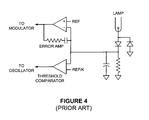
- the prior art approaches suggests measuring the unloaded resonant frequency and then tuning the open lamp operating frequency accordingly using an auxiliary resistor.
- Other approaches use a scanning technique that seems to adapt to normal component variations across the production spread.
- the inverter operating frequency is controlled independently from the regulation loops.
- the operating frequency is determined by a fixed frequency oscillator for normal operation after the lamp has ignited.
- the operating frequency can be locked to an external synchronization clock during normal operation.
- the operating frequency is swept higher in order to ensure adequate voltage at the output of the inverter module to strike the lamp.
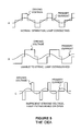
- the inverter operating frequency "tries” to run at a predetermined fixed frequency. However, if it is determined that the output current and voltage are out of phase by more than a threshold magnitude, then the "fixed" frequency control is overridden and the operating frequency is adjusted to bring the current and voltage substantially into phase.
- the idea of keeping the voltage and current in phase is taught in our U.S. Patent No. 6,114,814 in the context of optimizing switch efficiency. However, it has been found in the present invention that maintaining the correct phase relationship may also be used for generating enough voltage to strike the lamp.
- the waveforms for the operating point C are shown in Figure 5C.
- the criterion for this case is that the current through the primary winding and the driving voltage are once again substantially in phase.
- the technique for ensuring this is to drive the frequency higher until the trailing edge of the voltage wave form is substantially synchronous with the falling zero crossing of the current in the primary winding. Note that the lamp voltage regulator has narrowed the output pulse width because very little power is required to maintain strike voltage across the lamp when the driving voltage and the current across the primary winding are both in phase.
- the unloaded resonant frequency of the tank circuit can be easily found and the strike frequency is close enough to resonance to ensure plenty of open-lamp voltage. Because the trailing edge of the driving voltage and the falling zero crossing of the current across the primary winding are essentially coincidental, the frequency is constrained to the capacitive side (low side) of the resonant peak and can not hop over the peak of the upper curve 303 and run away on the high side.
- Another benefit is that, as soon as the lamp starts to dissipate power, the response curve of the tank circuit starts to change.
- the resonant peak starts moving down in frequency.
- the upper curve 303 slowly morphs into the lower curve 301 as you move from the unloaded condition to the loaded condition. Since the frequency controller tries to keep the operation on the capacitive side of resonance, the operating frequency starts sliding lower even before there is noticeable current in the lamp.
- the operating frequency remains nearly optimal throughout the start-up transient and moves towards the "fixed" operating frequency as early as possible. In other words, there is no need to detect the lamp current before leaving open lamp mode and approaching steady state run mode.
- the phase of the output stage current may be measured at different points.
- the voltage phase is determined by the output switch timing.
- the current may be measured in the output transistors as taught in U.S. Patent No. 6,114,814.
- the voltage phase may be determined by the output switch timing and the current may be measured at the cold end of the transformer primary.
- the current may be measured across the on-resistance of the power switches.
- the operating frequency is generated by a voltage-controlled oscillator (VCO).
- VCO voltage-controlled oscillator
- the operating frequency may be current controlled.
- the abbreviation VCO/ICO is used herein to identity both of these possibilities.
- the control input of the VCO/ICO is normally driven all the way to the low frequency of its control range or the VCO/ICO is synchronized to an external reference clock. This is the normal frequency after the lamp has been struck. The frequency is swept up higher when the falling zero crossing of the current flowing through the primary winding occurs in the second half of the driving voltage pulse. Small errors in setting the normal open frequency can be tolerated by the system because the loaded Q can be very low (Q ⁇ 1), which means the phase difference between voltage and current changes very slowly with frequency.
- the lamp has not ignited (or has extinguished or has been broken), operating at the normal frequency in a system adjusted as described above will cause the phase of the current waveform to lead the voltage significantly (capacitive load). This is evidence that the operating frequency is far removed from the resonant frequency of the tank. Depending on the quality of the components comprising the tank, it may not be possible to obtain adequate voltage on the secondary to guarantee that the lamp would strike.
- a simple Boolean expression that compares the phase lag of the output voltage with the zero-crossing of the output current provides an error correction signal to the control node of the VCO/ICO.
- the VCO/ICO can then be "swept up” in frequency until the voltage and current are once more substantially in phase. In this manner, there is sufficient gain in the tank to ensure striking the lamp. Once the lamp strikes, the output voltage no longer lags the output current and the VCO/ICO sweeps down to its normal operating frequency.
- the pulsed current source C1 drives the VCO control node and is much larger in magnitude (typically greater than ten times) than the weak current sink C2.
- the ratio of the magnitudes of the current sink and the pulsed current source determines the phase error allowed by the frequency control loop. If it is desired to lock the operating frequency to an external clock, then the weak current sink in Figure 6 would represent the maximum current available 'from the phase locked loop phase comparator block.
- the circuit of Figure 6 includes Boolean logic that operates as a phase comparator.
- the zero-crossing detector for the current flowing in the primary winding can be configured in many different ways for the various driver-staged topologies.
- the primary current can be sensed across the R dson of the switches in the bridge.
- the R dson in this example is measured across switches 2 and 4 of Figure 7 to sense the primary current.
- output stage that the current in the primary winding can be sensed in the return leg of the primary winding as seen in Figure 8 across R psense .
- the primary current can be sensed across the R dson of the switches in a push-pull output stage.
- the R dson in the example of Figure 9 is measured across switches 1 and 2 to sense the primary current.
- the circuit of Figure 10 shows multiple feedback paths through a common pulse-width modulator that controls lamp current, open lamp voltage, and secondary current. Because all three loops use the same compensation node and modulator, the system moves smoothly from one mode to another without annoying glitches and flashes that can occur when a loop is broken and the compensation node for one parameter drifts off to an extreme of its control range.
- the VCO control node can be driven with the output of a phase comparator.
- the oscillator would run near the low end of its control range.
- the same logic described above overwhelms the output of the phase comparator and drives the operating frequency up to the resonant frequency of the unloaded tank.
- the lamp current, lamp voltage, and secondary current are maintained by closed loops independent of the operating frequency.
- the multiple feedback paths converge on the same point to control various physical parameters in the system.
- one important feedback parameter is lamp current or lamp power. This is an important feedback path because it determines what the lamp looks like to the user and it can affect the lifetime of the lamp.
- all of these various feedback paths converge at the compensation (Comp) node.
- the advantage to this is that the voltage at the Comp node is maintained in its active region and the hand-off between the various control loops is smooth and well-behaved. Note that, if one or more of the loops did not use the common Comp node, then the Comp voltage is likely to wander off to some arbitrary voltage while a minor feedback path is in control. This would result in the feedback parameter that uses the Comp node to possibly be in error when control returns to it abruptly.
- the multiple feedback path concept may be expanded to any combination of several feedback parameters and ways of combining them in any particular controller.
- the main feedback parameter can be either lamp current sensed in a resistor or output power computed and averaged as taught in our U.S. Patent No. 6,114,814.
- Minor feedback parameters usually include lamp voltage (either balanced or unbalanced) in combination with some scheme of sensing module output current. Note that the output current does not necessarily return to the lamp current sense resistor -- it may dangerously pass from the high voltage side of the transformer secondary through an unfortunate person and directly to ground. Therefore, it is necessary to find a way to measure module output current that is independent of sensing the lamp current.
- the current may be sensed in the transformer secondary current.
- the current is sensed in the transformer primary, measuring it in the output power switches.
- the current in the secondary can be inferred from the current in the primary.
- the short circuit current in the secondary is very nearly the current in the primary divided by the turns ratio.
- Comp node Other parameters may be measured and fed back through the Comp node. For example, light output from the lamp could be measured with a photodiode and this parameter could "dither" the lamp current or power to guarantee uniform light across the production spread of panels, lamps, and modules.
- the lamp current may be sensed using a full-wave sense amplifier as described in our co-pending U.S. Patent Application Serial No. 10/354,541 entitled “FULL WAVE SENSE AMPLIFIER AND DISCHARGE LAMP INVERTER INCORPORATING THE SAME” filed January 29, 2003 which is hereby incorporated by reference in its entirety. Further, the amplifiers and comparators at the Comp node may also use a controlled-offset technique as described in our co-pending U.S. Patent Application Serial No. 10/656,087 entitled “CONTROLLED OFFSET AMPLIFIER” filed September 5, 2003 which is hereby incorporated by reference in its entirety.
Landscapes
- Circuit Arrangements For Discharge Lamps (AREA)
- Inverter Devices (AREA)
Applications Claiming Priority (2)
| Application Number | Priority Date | Filing Date | Title |
|---|---|---|---|
| US677612 | 2000-10-03 | ||
| US10/677,612 US6919694B2 (en) | 2003-10-02 | 2003-10-02 | Fixed operating frequency inverter for cold cathode fluorescent lamp having strike frequency adjusted by voltage to current phase relationship |
Publications (1)
| Publication Number | Publication Date |
|---|---|
| EP1521507A1 true EP1521507A1 (de) | 2005-04-06 |
Family
ID=34314057
Family Applications (1)
| Application Number | Title | Priority Date | Filing Date |
|---|---|---|---|
| EP04251532A Withdrawn EP1521507A1 (de) | 2003-10-02 | 2004-03-18 | Verfahren und Vorrichtung zum Betrieb einer Entladungslampe |
Country Status (6)
| Country | Link |
|---|---|
| US (3) | US6919694B2 (de) |
| EP (1) | EP1521507A1 (de) |
| JP (1) | JP4083126B2 (de) |
| KR (1) | KR100620479B1 (de) |
| CN (1) | CN100512590C (de) |
| TW (1) | TW200514116A (de) |
Cited By (2)
| Publication number | Priority date | Publication date | Assignee | Title |
|---|---|---|---|---|
| WO2006131890A3 (en) * | 2005-06-10 | 2007-02-22 | Koninkl Philips Electronics Nv | A control device for controlling the output of one or more full-bridges |
| EP2175699A4 (de) * | 2007-07-26 | 2014-01-01 | Panasonic Corp | Elektronische vorschaltung für eine entladungslampe |
Families Citing this family (20)
| Publication number | Priority date | Publication date | Assignee | Title |
|---|---|---|---|---|
| US6919694B2 (en) * | 2003-10-02 | 2005-07-19 | Monolithic Power Systems, Inc. | Fixed operating frequency inverter for cold cathode fluorescent lamp having strike frequency adjusted by voltage to current phase relationship |
| US7368879B2 (en) * | 2004-02-19 | 2008-05-06 | International Rectifier Corporation | Pendulum resonant converter and method |
| US20060186833A1 (en) * | 2005-02-23 | 2006-08-24 | Yu Chung-Che | Fluorescent tube driver circuit system of pulse-width modulation control |
| JP2006244908A (ja) * | 2005-03-04 | 2006-09-14 | Koito Mfg Co Ltd | 放電灯点灯回路 |
| EP1869759B1 (de) * | 2005-04-01 | 2019-08-07 | Nxp B.V. | Steuerung eines resonanzwandlers |
| TW200707888A (en) * | 2005-04-20 | 2007-02-16 | Intersil Inc | DC-AC converter having phase-modulated, double-ended bridge topology for powering high voltage load such as cold cathode fluorescent lamp |
| CN1856206B (zh) * | 2005-04-25 | 2010-06-09 | 明基电通股份有限公司 | 稳定一冷阴极灯管亮度的方法及其相关装置 |
| KR100631986B1 (ko) * | 2005-06-13 | 2006-10-09 | 삼성전기주식회사 | 냉음극 형광 램프의 구동 장치 |
| KR100631987B1 (ko) * | 2005-06-20 | 2006-10-09 | 삼성전기주식회사 | 냉음극 형광 램프의 구동 장치 |
| TW200711537A (en) * | 2005-07-07 | 2007-03-16 | Koninkl Philips Electronics Nv | Parasitic capacitance compensations system and method |
| US7420829B2 (en) * | 2005-08-25 | 2008-09-02 | Monolithic Power Systems, Inc. | Hybrid control for discharge lamps |
| US7382636B2 (en) * | 2005-10-14 | 2008-06-03 | Access Business Group International Llc | System and method for powering a load |
| US7394203B2 (en) * | 2005-12-15 | 2008-07-01 | Monolithic Power Systems, Inc. | Method and system for open lamp protection |
| US7423388B2 (en) * | 2006-02-15 | 2008-09-09 | Monolithic Power Systems, Inc. | Fixed lamp frequency synchronization with the resonant tank for discharge lamps |
| NZ553000A (en) * | 2007-02-02 | 2009-09-25 | Advanced Environmental Technol | Switching technique for efficient electrical power utilization |
| US7570358B2 (en) * | 2007-03-30 | 2009-08-04 | Asml Netherlands Bv | Angularly resolved scatterometer, inspection method, lithographic apparatus, lithographic processing cell device manufacturing method and alignment sensor |
| CN101583229B (zh) * | 2008-05-15 | 2013-01-09 | 杭州茂力半导体技术有限公司 | 多放电灯并联驱动电路及驱动方法 |
| TW201030275A (en) * | 2009-10-26 | 2010-08-16 | ding-cheng Lai | Lamp tube and lamp tube module |
| US10695740B2 (en) | 2013-11-25 | 2020-06-30 | Imalog Inc. | Method and device for controlling an ozone generator power supply |
| CN109587912B (zh) * | 2018-12-03 | 2023-07-21 | 北京蓝天创通科技有限责任公司 | 一种用于铁路信号机主灯丝的断丝报警系统 |
Citations (5)
| Publication number | Priority date | Publication date | Assignee | Title |
|---|---|---|---|---|
| US6114814A (en) | 1998-12-11 | 2000-09-05 | Monolithic Power Systems, Inc. | Apparatus for controlling a discharge lamp in a backlighted display |
| US6226196B1 (en) * | 1999-04-16 | 2001-05-01 | Murata Manufacturing Co., Ltd. | Piezoelectric transformer inverter |
| US6348755B1 (en) | 1999-04-22 | 2002-02-19 | Taiyo Yuden, Co., Ltd. | Method and apparatus for driving piezoelectric transformer |
| EP1296542A1 (de) * | 2001-09-21 | 2003-03-26 | Minebea Co., Ltd. | Wechselrichter für eine Entladungslampe |
| US20030160572A1 (en) * | 2002-02-27 | 2003-08-28 | Texas Instruments Incorporated | Control circuit employing preconditioned feedback amplifier for initializing vco operating frequency |
Family Cites Families (69)
| Publication number | Priority date | Publication date | Assignee | Title |
|---|---|---|---|---|
| CA1053761A (en) * | 1974-12-13 | 1979-05-01 | White-Westinghouse Corporation | Induction cooking apparatus |
| US5481160A (en) | 1978-03-20 | 1996-01-02 | Nilssen; Ole K. | Electronic ballast with FET bridge inverter |
| US5402043A (en) | 1978-03-20 | 1995-03-28 | Nilssen; Ole K. | Controlled driven series-resonant ballast |
| US6002210A (en) | 1978-03-20 | 1999-12-14 | Nilssen; Ole K. | Electronic ballast with controlled-magnitude output voltage |
| US5422546A (en) | 1978-03-20 | 1995-06-06 | Nilssen; Ole K. | Dimmable parallel-resonant electric ballast |
| US5744915A (en) | 1978-03-20 | 1998-04-28 | Nilssen; Ole K. | Electronic ballast for instant-start lamps |
| US4277728A (en) | 1978-05-08 | 1981-07-07 | Stevens Luminoptics | Power supply for a high intensity discharge or fluorescent lamp |
| US4504895A (en) | 1982-11-03 | 1985-03-12 | General Electric Company | Regulated dc-dc converter using a resonating transformer |
| US4541041A (en) | 1983-08-22 | 1985-09-10 | General Electric Company | Full load to no-load control for a voltage fed resonant inverter |
| US4672528A (en) | 1986-05-27 | 1987-06-09 | General Electric Company | Resonant inverter with improved control |
| JPH07118915B2 (ja) | 1987-01-30 | 1995-12-18 | 株式会社日立メデイコ | 共振型dc−dcコンバ−タ |
| US4727469A (en) | 1987-03-23 | 1988-02-23 | Reliance Comm/Tec Corporation | Control for a series resonant power converter |
| NL8800288A (nl) | 1988-02-08 | 1989-09-01 | Nedap Nv | Voorschakelapparaat voor een fluorescentielamp. |
| JP2618685B2 (ja) * | 1988-05-19 | 1997-06-11 | ティーディーケイ株式会社 | 圧電振動子駆動回路 |
| US4952849A (en) * | 1988-07-15 | 1990-08-28 | North American Philips Corporation | Fluorescent lamp controllers |
| US4855888A (en) | 1988-10-19 | 1989-08-08 | Unisys Corporation | Constant frequency resonant power converter with zero voltage switching |
| FR2649277B1 (fr) | 1989-06-30 | 1996-05-31 | Thomson Csf | Procede et dispositif de gradation de lumiere pour lampe fluorescente d'eclairage arriere d'ecran a cristaux liquides |
| JPH0355794A (ja) | 1989-07-24 | 1991-03-11 | Hitachi Ltd | 放電灯点灯装置 |
| US4935857A (en) | 1989-08-22 | 1990-06-19 | Sundstrand Corporation | Transistor conduction-angle control for a series-parallel resonant converter |
| US4992919A (en) | 1989-12-29 | 1991-02-12 | Lee Chu Quon | Parallel resonant converter with zero voltage switching |
| US5270620A (en) | 1990-09-04 | 1993-12-14 | General Electric Company | High frequency resonant converter for operating metal halide lamps |
| CA2096624A1 (en) | 1990-12-03 | 1992-06-04 | Woodrow L. Antle | Wide dimming range gas discharge lamp drive system |
| US5130611A (en) * | 1991-01-16 | 1992-07-14 | Intent Patents A.G. | Universal electronic ballast system |
| JP2826918B2 (ja) | 1991-10-11 | 1998-11-18 | キヤノン株式会社 | 高圧交流電圧発生回路 |
| US5157592A (en) | 1991-10-15 | 1992-10-20 | International Business Machines Corporation | DC-DC converter with adaptive zero-voltage switching |
| US5285372A (en) | 1991-10-23 | 1994-02-08 | Henkel Corporation | Power supply for an ozone generator with a bridge inverter |
| US5384516A (en) | 1991-11-06 | 1995-01-24 | Hitachi, Ltd. | Information processing apparatus including a control circuit for controlling a liquid crystal display illumination based on whether illuminatio power is being supplied from an AC power source or from a battery |
| US5442540A (en) | 1992-06-12 | 1995-08-15 | The Center For Innovative Technology | Soft-switching PWM converters |
| US5315498A (en) | 1992-12-23 | 1994-05-24 | International Business Machines Corporation | Apparatus providing leading leg current sensing for control of full bridge power supply |
| US5363020A (en) | 1993-02-05 | 1994-11-08 | Systems And Service International, Inc. | Electronic power controller |
| US5438497A (en) | 1993-05-13 | 1995-08-01 | Northern Telecom Limited | Tertiary side resonant DC/DC converter |
| US5438242A (en) | 1993-06-24 | 1995-08-01 | Fusion Systems Corporation | Apparatus for controlling the brightness of a magnetron-excited lamp |
| US5477131A (en) | 1993-09-02 | 1995-12-19 | Motorola, Inc. | Zero-voltage-transition switching power converters using magnetic feedback |
| US5416387A (en) | 1993-11-24 | 1995-05-16 | California Institute Of Technology | Single stage, high power factor, gas discharge lamp ballast |
| US5438498A (en) | 1993-12-21 | 1995-08-01 | Raytheon Company | Series resonant converter having a resonant snubber |
| US5583402A (en) | 1994-01-31 | 1996-12-10 | Magnetek, Inc. | Symmetry control circuit and method |
| US5481449A (en) | 1994-03-21 | 1996-01-02 | General Electric Company | Efficient, high power density, high power factor converter for very low dc voltage applications |
| CH688952B5 (fr) | 1994-05-26 | 1998-12-31 | Ebauchesfabrik Eta Ag | Circuit d'alimentation pour une feuille électroluminescente. |
| JP3027298B2 (ja) | 1994-05-31 | 2000-03-27 | シャープ株式会社 | バックライト制御機能付き液晶表示装置 |
| US5615093A (en) | 1994-08-05 | 1997-03-25 | Linfinity Microelectronics | Current synchronous zero voltage switching resonant topology |
| US5550436A (en) | 1994-09-01 | 1996-08-27 | International Rectifier Corporation | MOS gate driver integrated circuit for ballast circuits |
| KR0138306B1 (ko) | 1994-12-14 | 1998-06-15 | 김광호 | 영전압 스위칭 제어회로 |
| US5754012A (en) | 1995-01-25 | 1998-05-19 | Micro Linear Corporation | Primary side lamp current sensing for minature cold cathode fluorescent lamp system |
| US5604411A (en) | 1995-03-31 | 1997-02-18 | Philips Electronics North America Corporation | Electronic ballast having a triac dimming filter with preconditioner offset control |
| US5694007A (en) | 1995-04-19 | 1997-12-02 | Systems And Services International, Inc. | Discharge lamp lighting system for avoiding high in-rush current |
| US5677602A (en) | 1995-05-26 | 1997-10-14 | Paul; Jon D. | High efficiency electronic ballast for high intensity discharge lamps |
| US5875103A (en) | 1995-12-22 | 1999-02-23 | Electronic Measurements, Inc. | Full range soft-switching DC-DC converter |
| WO1997024016A1 (en) | 1995-12-26 | 1997-07-03 | General Electric Company | Control and protection of dimmable electronic fluorescent lamp ballast with wide input voltage range and wide dimming range |
| US5619402A (en) | 1996-04-16 | 1997-04-08 | O2 Micro, Inc. | Higher-efficiency cold-cathode fluorescent lamp power supply |
| CN1126146C (zh) | 1996-05-09 | 2003-10-29 | 皇家菲利浦电子有限公司 | 高压放电灯 |
| US5719474A (en) | 1996-06-14 | 1998-02-17 | Loral Corporation | Fluorescent lamps with current-mode driver control |
| US5781418A (en) | 1996-12-23 | 1998-07-14 | Philips Electronics North America Corporation | Switching scheme for power supply having a voltage-fed inverter |
| US5932976A (en) | 1997-01-14 | 1999-08-03 | Matsushita Electric Works R&D Laboratory, Inc. | Discharge lamp driving |
| US6011360A (en) * | 1997-02-13 | 2000-01-04 | Philips Electronics North America Corporation | High efficiency dimmable cold cathode fluorescent lamp ballast |
| US5923129A (en) | 1997-03-14 | 1999-07-13 | Linfinity Microelectronics | Apparatus and method for starting a fluorescent lamp |
| US5930121A (en) | 1997-03-14 | 1999-07-27 | Linfinity Microelectronics | Direct drive backlight system |
| JP3216572B2 (ja) | 1997-05-27 | 2001-10-09 | 日本電気株式会社 | 圧電トランスの駆動回路 |
| US5940709A (en) | 1997-12-18 | 1999-08-17 | Advanced Micro Devices, Inc. | Method and system for source only reoxidation after junction implant for flash memory devices |
| US5939830A (en) | 1997-12-24 | 1999-08-17 | Honeywell Inc. | Method and apparatus for dimming a lamp in a backlight of a liquid crystal display |
| US6016052A (en) | 1998-04-03 | 2000-01-18 | Cts Corporation | Pulse frequency modulation drive circuit for piezoelectric transformer |
| US6900600B2 (en) * | 1998-12-11 | 2005-05-31 | Monolithic Power Systems, Inc. | Method for starting a discharge lamp using high energy initial pulse |
| US6108215A (en) * | 1999-01-22 | 2000-08-22 | Dell Computer Corporation | Voltage regulator with double synchronous bridge CCFL inverter |
| US6198234B1 (en) | 1999-06-09 | 2001-03-06 | Linfinity Microelectronics | Dimmable backlight system |
| US6259615B1 (en) * | 1999-07-22 | 2001-07-10 | O2 Micro International Limited | High-efficiency adaptive DC/AC converter |
| US6900599B2 (en) * | 2001-03-22 | 2005-05-31 | International Rectifier Corporation | Electronic dimming ballast for cold cathode fluorescent lamp |
| US6683422B1 (en) * | 2003-01-29 | 2004-01-27 | Monolithic Power Systems, Inc. | Full wave sense amplifier and discharge lamp inverter incorporating the same |
| US6919694B2 (en) * | 2003-10-02 | 2005-07-19 | Monolithic Power Systems, Inc. | Fixed operating frequency inverter for cold cathode fluorescent lamp having strike frequency adjusted by voltage to current phase relationship |
| US7187140B2 (en) * | 2003-12-16 | 2007-03-06 | Microsemi Corporation | Lamp current control using profile synthesizer |
| CN1953631A (zh) * | 2005-10-17 | 2007-04-25 | 美国芯源系统股份有限公司 | 一种适合冷阴极荧光灯背光应用的直流/交流电源装置 |
-
2003
- 2003-10-02 US US10/677,612 patent/US6919694B2/en not_active Expired - Lifetime
-
2004
- 2004-02-05 JP JP2004029258A patent/JP4083126B2/ja not_active Expired - Fee Related
- 2004-02-11 KR KR1020040008942A patent/KR100620479B1/ko not_active Expired - Fee Related
- 2004-02-24 TW TW093104688A patent/TW200514116A/zh not_active IP Right Cessation
- 2004-03-18 EP EP04251532A patent/EP1521507A1/de not_active Withdrawn
- 2004-05-27 CN CNB2004100476461A patent/CN100512590C/zh not_active Expired - Fee Related
-
2005
- 2005-02-16 US US11/060,237 patent/US7294974B2/en not_active Ceased
-
2009
- 2009-11-13 US US12/617,924 patent/USRE44133E1/en not_active Expired - Lifetime
Patent Citations (5)
| Publication number | Priority date | Publication date | Assignee | Title |
|---|---|---|---|---|
| US6114814A (en) | 1998-12-11 | 2000-09-05 | Monolithic Power Systems, Inc. | Apparatus for controlling a discharge lamp in a backlighted display |
| US6226196B1 (en) * | 1999-04-16 | 2001-05-01 | Murata Manufacturing Co., Ltd. | Piezoelectric transformer inverter |
| US6348755B1 (en) | 1999-04-22 | 2002-02-19 | Taiyo Yuden, Co., Ltd. | Method and apparatus for driving piezoelectric transformer |
| EP1296542A1 (de) * | 2001-09-21 | 2003-03-26 | Minebea Co., Ltd. | Wechselrichter für eine Entladungslampe |
| US20030160572A1 (en) * | 2002-02-27 | 2003-08-28 | Texas Instruments Incorporated | Control circuit employing preconditioned feedback amplifier for initializing vco operating frequency |
Cited By (3)
| Publication number | Priority date | Publication date | Assignee | Title |
|---|---|---|---|---|
| WO2006131890A3 (en) * | 2005-06-10 | 2007-02-22 | Koninkl Philips Electronics Nv | A control device for controlling the output of one or more full-bridges |
| US8648789B2 (en) | 2005-06-10 | 2014-02-11 | Nxp, B.V. | Control device for controlling the output of one or more full-bridges |
| EP2175699A4 (de) * | 2007-07-26 | 2014-01-01 | Panasonic Corp | Elektronische vorschaltung für eine entladungslampe |
Also Published As
| Publication number | Publication date |
|---|---|
| US20050073266A1 (en) | 2005-04-07 |
| TW200514116A (en) | 2005-04-16 |
| US7294974B2 (en) | 2007-11-13 |
| KR20050032988A (ko) | 2005-04-08 |
| KR100620479B1 (ko) | 2006-09-13 |
| USRE44133E1 (en) | 2013-04-09 |
| CN1604715A (zh) | 2005-04-06 |
| US20050140313A1 (en) | 2005-06-30 |
| CN100512590C (zh) | 2009-07-08 |
| US6919694B2 (en) | 2005-07-19 |
| JP2005117881A (ja) | 2005-04-28 |
| JP4083126B2 (ja) | 2008-04-30 |
| TWI296811B (de) | 2008-05-11 |
Similar Documents
| Publication | Publication Date | Title |
|---|---|---|
| USRE44133E1 (en) | Fixed operating frequency inverter for cold cathode fluorescent lamp having strike frequency adjusted by voltage to current phase relationship | |
| US7876060B2 (en) | Multi-lamps instant start electronic ballast | |
| EP0763311B1 (de) | Vorschaltgerät für eine entladungslampe | |
| EP2064927B1 (de) | Lampenantriebsschaltung und verfahren zum antreiben einer entladungslampe | |
| US7911153B2 (en) | Electronic ballasts for lighting systems | |
| US5402043A (en) | Controlled driven series-resonant ballast | |
| KR100853869B1 (ko) | 디밍 밸러스트 제어 회로 | |
| US8400074B2 (en) | Electronic ballast with feedback current control for preheating of lamp filaments | |
| US7242154B2 (en) | Circuit arrangement and method for operation of lamps | |
| KR20040058248A (ko) | 방전 램프용 밸러스트 장치 | |
| US6377000B2 (en) | Electronic ballast for gas discharge lamp | |
| US6031342A (en) | Universal input warm-start linear ballast | |
| US7312586B2 (en) | Ballast power supply | |
| CN100539379C (zh) | 包含具有可变偏流源的反馈电路的谐振逆变器 | |
| US8339056B1 (en) | Lamp ballast with protection circuit for input arcing and line interruption | |
| US6414449B1 (en) | Universal electronic ballast | |
| US7656096B2 (en) | Hybrid ballast control circuit in a simplified package | |
| US6841951B2 (en) | Single stage HID electronic ballast | |
| JPH10149888A (ja) | 照明用点灯装置及びその制御方法 | |
| US6677718B2 (en) | HID electronic ballast with glow to arc and warm-up control | |
| US20070145905A1 (en) | Driver device for a gas discharge lamp and igniter | |
| Ribas et al. | High frequency electronic ballast for metal halide lamps based on a PLL controlled class E resonant inverter | |
| JP2008166290A (ja) | 単純化されたパッケージにおける混成安定器制御回路 | |
| Huang et al. | Designing a wide range high performance T5HO electronic ballast platform | |
| JP2003197394A (ja) | 放電灯点灯装置 |
Legal Events
| Date | Code | Title | Description |
|---|---|---|---|
| PUAI | Public reference made under article 153(3) epc to a published international application that has entered the european phase |
Free format text: ORIGINAL CODE: 0009012 |
|
| 17P | Request for examination filed |
Effective date: 20040318 |
|
| AK | Designated contracting states |
Kind code of ref document: A1 Designated state(s): AT BE BG CH CY CZ DE DK EE ES FI FR GB GR HU IE IT LI LU MC NL PL PT RO SE SI SK TR |
|
| AX | Request for extension of the european patent |
Extension state: AL HR LT LV MK |
|
| AKX | Designation fees paid |
Designated state(s): AT BE BG CH CY CZ DE DK EE ES FI FR GB GR HU IE IT LI LU MC NL PL PT RO SE SI SK TR |
|
| 17Q | First examination report despatched |
Effective date: 20070306 |
|
| STAA | Information on the status of an ep patent application or granted ep patent |
Free format text: STATUS: THE APPLICATION IS DEEMED TO BE WITHDRAWN |
|
| 18D | Application deemed to be withdrawn |
Effective date: 20111005 |