EP1521684B1 - Klimaanlage mit abschaltungsisolierung und entlüftung eines verdampfers unter verwendung eines h-förmigem ventils - Google Patents
Klimaanlage mit abschaltungsisolierung und entlüftung eines verdampfers unter verwendung eines h-förmigem ventils Download PDFInfo
- Publication number
- EP1521684B1 EP1521684B1 EP03739281A EP03739281A EP1521684B1 EP 1521684 B1 EP1521684 B1 EP 1521684B1 EP 03739281 A EP03739281 A EP 03739281A EP 03739281 A EP03739281 A EP 03739281A EP 1521684 B1 EP1521684 B1 EP 1521684B1
- Authority
- EP
- European Patent Office
- Prior art keywords
- liquid
- valve
- suction
- pass
- fluid line
- Prior art date
- Legal status (The legal status is an assumption and is not a legal conclusion. Google has not performed a legal analysis and makes no representation as to the accuracy of the status listed.)
- Expired - Lifetime
Links
Images

Classifications
-
- B—PERFORMING OPERATIONS; TRANSPORTING
- B60—VEHICLES IN GENERAL
- B60H—ARRANGEMENTS OF HEATING, COOLING, VENTILATING OR OTHER AIR-TREATING DEVICES SPECIALLY ADAPTED FOR PASSENGER OR GOODS SPACES OF VEHICLES
- B60H1/00—Heating, cooling or ventilating devices
- B60H1/32—Cooling devices
- B60H1/3204—Cooling devices using compression
- B60H1/3205—Control means therefor
- B60H1/3214—Control means therefor for improving the lubrication of a refrigerant compressor in a vehicle
-
- B—PERFORMING OPERATIONS; TRANSPORTING
- B60—VEHICLES IN GENERAL
- B60H—ARRANGEMENTS OF HEATING, COOLING, VENTILATING OR OTHER AIR-TREATING DEVICES SPECIALLY ADAPTED FOR PASSENGER OR GOODS SPACES OF VEHICLES
- B60H1/00—Heating, cooling or ventilating devices
- B60H1/00485—Valves for air-conditioning devices, e.g. thermostatic valves
-
- B—PERFORMING OPERATIONS; TRANSPORTING
- B60—VEHICLES IN GENERAL
- B60H—ARRANGEMENTS OF HEATING, COOLING, VENTILATING OR OTHER AIR-TREATING DEVICES SPECIALLY ADAPTED FOR PASSENGER OR GOODS SPACES OF VEHICLES
- B60H1/00—Heating, cooling or ventilating devices
- B60H1/00642—Control systems or circuits; Control members or indication devices for heating, cooling or ventilating devices
- B60H1/00814—Control systems or circuits characterised by their output, for controlling particular components of the heating, cooling or ventilating installation
- B60H1/00878—Control systems or circuits characterised by their output, for controlling particular components of the heating, cooling or ventilating installation the components being temperature regulating devices
- B60H1/00885—Controlling the flow of heating or cooling liquid, e.g. valves or pumps
-
- B—PERFORMING OPERATIONS; TRANSPORTING
- B60—VEHICLES IN GENERAL
- B60H—ARRANGEMENTS OF HEATING, COOLING, VENTILATING OR OTHER AIR-TREATING DEVICES SPECIALLY ADAPTED FOR PASSENGER OR GOODS SPACES OF VEHICLES
- B60H1/00—Heating, cooling or ventilating devices
- B60H1/32—Cooling devices
- B60H1/3204—Cooling devices using compression
- B60H1/3205—Control means therefor
-
- B—PERFORMING OPERATIONS; TRANSPORTING
- B60—VEHICLES IN GENERAL
- B60H—ARRANGEMENTS OF HEATING, COOLING, VENTILATING OR OTHER AIR-TREATING DEVICES SPECIALLY ADAPTED FOR PASSENGER OR GOODS SPACES OF VEHICLES
- B60H1/00—Heating, cooling or ventilating devices
- B60H1/32—Cooling devices
- B60H1/3204—Cooling devices using compression
- B60H1/3205—Control means therefor
- B60H1/3217—Control means therefor for high pressure, inflamable or poisonous refrigerants causing danger in case of accidents
-
- B—PERFORMING OPERATIONS; TRANSPORTING
- B60—VEHICLES IN GENERAL
- B60H—ARRANGEMENTS OF HEATING, COOLING, VENTILATING OR OTHER AIR-TREATING DEVICES SPECIALLY ADAPTED FOR PASSENGER OR GOODS SPACES OF VEHICLES
- B60H1/00—Heating, cooling or ventilating devices
- B60H1/32—Cooling devices
- B60H1/3204—Cooling devices using compression
- B60H1/3225—Cooling devices using compression characterised by safety arrangements, e.g. compressor anti-seizure means or by signalling devices
-
- F—MECHANICAL ENGINEERING; LIGHTING; HEATING; WEAPONS; BLASTING
- F25—REFRIGERATION OR COOLING; COMBINED HEATING AND REFRIGERATION SYSTEMS; HEAT PUMP SYSTEMS; MANUFACTURE OR STORAGE OF ICE; LIQUEFACTION SOLIDIFICATION OF GASES
- F25B—REFRIGERATION MACHINES, PLANTS OR SYSTEMS; COMBINED HEATING AND REFRIGERATION SYSTEMS; HEAT PUMP SYSTEMS
- F25B41/00—Fluid-circulation arrangements
- F25B41/20—Disposition of valves, e.g. of on-off valves or flow control valves
-
- B—PERFORMING OPERATIONS; TRANSPORTING
- B60—VEHICLES IN GENERAL
- B60H—ARRANGEMENTS OF HEATING, COOLING, VENTILATING OR OTHER AIR-TREATING DEVICES SPECIALLY ADAPTED FOR PASSENGER OR GOODS SPACES OF VEHICLES
- B60H1/00—Heating, cooling or ventilating devices
- B60H1/32—Cooling devices
- B60H2001/3236—Cooling devices information from a variable is obtained
- B60H2001/3238—Cooling devices information from a variable is obtained related to the operation of the compressor
-
- B—PERFORMING OPERATIONS; TRANSPORTING
- B60—VEHICLES IN GENERAL
- B60H—ARRANGEMENTS OF HEATING, COOLING, VENTILATING OR OTHER AIR-TREATING DEVICES SPECIALLY ADAPTED FOR PASSENGER OR GOODS SPACES OF VEHICLES
- B60H1/00—Heating, cooling or ventilating devices
- B60H1/32—Cooling devices
- B60H2001/3269—Cooling devices output of a control signal
- B60H2001/327—Cooling devices output of a control signal related to a compressing unit
- B60H2001/3275—Cooling devices output of a control signal related to a compressing unit to control the volume of a compressor
-
- B—PERFORMING OPERATIONS; TRANSPORTING
- B60—VEHICLES IN GENERAL
- B60H—ARRANGEMENTS OF HEATING, COOLING, VENTILATING OR OTHER AIR-TREATING DEVICES SPECIALLY ADAPTED FOR PASSENGER OR GOODS SPACES OF VEHICLES
- B60H1/00—Heating, cooling or ventilating devices
- B60H1/32—Cooling devices
- B60H2001/3269—Cooling devices output of a control signal
- B60H2001/328—Cooling devices output of a control signal related to an evaporating unit
- B60H2001/3283—Cooling devices output of a control signal related to an evaporating unit to control the refrigerant flow
-
- F—MECHANICAL ENGINEERING; LIGHTING; HEATING; WEAPONS; BLASTING
- F25—REFRIGERATION OR COOLING; COMBINED HEATING AND REFRIGERATION SYSTEMS; HEAT PUMP SYSTEMS; MANUFACTURE OR STORAGE OF ICE; LIQUEFACTION SOLIDIFICATION OF GASES
- F25B—REFRIGERATION MACHINES, PLANTS OR SYSTEMS; COMBINED HEATING AND REFRIGERATION SYSTEMS; HEAT PUMP SYSTEMS
- F25B2400/00—Component parts or details not otherwise provided for in this subclass
- F25B2400/04—Refrigeration circuit bypassing means
- F25B2400/0409—Refrigeration circuit bypassing means for evaporators
-
- F—MECHANICAL ENGINEERING; LIGHTING; HEATING; WEAPONS; BLASTING
- F25—REFRIGERATION OR COOLING; COMBINED HEATING AND REFRIGERATION SYSTEMS; HEAT PUMP SYSTEMS; MANUFACTURE OR STORAGE OF ICE; LIQUEFACTION SOLIDIFICATION OF GASES
- F25B—REFRIGERATION MACHINES, PLANTS OR SYSTEMS; COMBINED HEATING AND REFRIGERATION SYSTEMS; HEAT PUMP SYSTEMS
- F25B25/00—Machines, plants or systems, using a combination of modes of operation covered by two or more of the groups F25B1/00 - F25B23/00
-
- F—MECHANICAL ENGINEERING; LIGHTING; HEATING; WEAPONS; BLASTING
- F25—REFRIGERATION OR COOLING; COMBINED HEATING AND REFRIGERATION SYSTEMS; HEAT PUMP SYSTEMS; MANUFACTURE OR STORAGE OF ICE; LIQUEFACTION SOLIDIFICATION OF GASES
- F25B—REFRIGERATION MACHINES, PLANTS OR SYSTEMS; COMBINED HEATING AND REFRIGERATION SYSTEMS; HEAT PUMP SYSTEMS
- F25B2500/00—Problems to be solved
- F25B2500/22—Preventing, detecting or repairing leaks of refrigeration fluids
- F25B2500/221—Preventing leaks from developing
-
- F—MECHANICAL ENGINEERING; LIGHTING; HEATING; WEAPONS; BLASTING
- F25—REFRIGERATION OR COOLING; COMBINED HEATING AND REFRIGERATION SYSTEMS; HEAT PUMP SYSTEMS; MANUFACTURE OR STORAGE OF ICE; LIQUEFACTION SOLIDIFICATION OF GASES
- F25B—REFRIGERATION MACHINES, PLANTS OR SYSTEMS; COMBINED HEATING AND REFRIGERATION SYSTEMS; HEAT PUMP SYSTEMS
- F25B2500/00—Problems to be solved
- F25B2500/27—Problems to be solved characterised by the stop of the refrigeration cycle
-
- F—MECHANICAL ENGINEERING; LIGHTING; HEATING; WEAPONS; BLASTING
- F25—REFRIGERATION OR COOLING; COMBINED HEATING AND REFRIGERATION SYSTEMS; HEAT PUMP SYSTEMS; MANUFACTURE OR STORAGE OF ICE; LIQUEFACTION SOLIDIFICATION OF GASES
- F25B—REFRIGERATION MACHINES, PLANTS OR SYSTEMS; COMBINED HEATING AND REFRIGERATION SYSTEMS; HEAT PUMP SYSTEMS
- F25B2600/00—Control issues
- F25B2600/02—Compressor control
- F25B2600/023—Compressor control controlling swash plate angles
-
- F—MECHANICAL ENGINEERING; LIGHTING; HEATING; WEAPONS; BLASTING
- F25—REFRIGERATION OR COOLING; COMBINED HEATING AND REFRIGERATION SYSTEMS; HEAT PUMP SYSTEMS; MANUFACTURE OR STORAGE OF ICE; LIQUEFACTION SOLIDIFICATION OF GASES
- F25B—REFRIGERATION MACHINES, PLANTS OR SYSTEMS; COMBINED HEATING AND REFRIGERATION SYSTEMS; HEAT PUMP SYSTEMS
- F25B2600/00—Control issues
- F25B2600/05—Refrigerant levels
Definitions
- the subject invention relates to an air conditioning system for a vehicle, frequently referred to as a heating, ventilating and air conditioning (HVAC) system.
- HVAC heating, ventilating and air conditioning
- Such systems typically include a compressor for compressing a refrigerant, a condenser for condensing the refrigerant, an evaporator for evaporating the refrigerant, a discharge fluid line interconnecting the compressor and the condenser, a liquid fluid line interconnecting the evaporator and the condenser, and a suction fluid line interconnecting the evaporator and the compressor.
- Such systems utilize various valve arrangements for controlling flow through the system during operation and during shutdown and/or in response to a leak of refrigerant in the system.
- Some systems employ valves for bypassing the flow of refrigerant around the evaporator. However, such systems normally include the attendant plumbing for affecting the by-pass.
- the subject invention provides a compact by-pass arrangement that includes the valves and may be disposed next to or adjacent to the evaporator.
- the invention includes a valve body having a by-pass passage extending between the liquid and suction fluid lines, a by-pass valve at the intersection of the liquid fluid line and the by-pass passage.
- the by-pass valve has a normal operating position for directing fluid flow from the liquid fluid line to the evaporator and a by-pass position for directing fluid flow from the liquid fluid line to the by-pass passage.
- the valve also includes a by-pass check valve for allowing only one-way fluid flow through the by-pass passage when the by-pass valve is in the by-pass position.
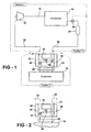
- Figure 1 is schematic view of a first system incorporating the subject invention with the by-pass valve in the by-pass position;
- Figure 2 is a schematic view of the first system with the by-pass valve in the normal operating position
- Figure 3 is a schematic view of a second system incorporating the subject invention with the by-pass valve in the by-pass position;
- Figure 4 is a schematic view of the second system with the by-pass valve in the normal operating position.
- An air conditioning system for a vehicle is shown schematically in Figure 1 and typically comprises a compressor 12 for compressing a refrigerant, a condenser 14 for condensing the refrigerant, and an evaporator 16 for evaporating the refrigerant.
- a discharge fluid line 18 interconnects the compressor 12 and the condenser 14 and a liquid fluid line 20 interconnects the condenser 14 and the evaporator 16, while a suction fluid line 22 interconnects the evaporator 16 and the compressor 12.
- a receiver/drier (R/D) 24 (Fig. 1) may be disposed in the liquid fluid line 20 and in others an accumulator/dehydrator (A/D) 26 (Fig. 3) may be disposed in the suction fluid line 22 (as is well known in the art).
- FIG 1 represents a system configuration wherein a thermal expansion valve (TXV) 28 is disposed in the fluid lines 20 and 22 into and out of the evaporator 16 and
- Figure 3 represents an expansion device 30, such as an orifice tube, being intermediate between the condenser 14 and the evaporator 16 in the liquid fluid line 20.
- TXV thermal expansion valve
- the system includes an integral valve 32 having a by-pass passage 34 extending between the liquid 20 and suction 22 fluid lines.
- the integral valve 32 includes a by-pass valve 36 at the intersection of the liquid fluid line 20 and the by-pass passage 34 that has a normal operating position for directing fluid flow from the liquid fluid line 20 to the evaporator 16 and a by-pass position for directing fluid flow through the by-pass passage 34.
- the integral valve 32 also includes a by-pass check valve 38, 40 for allowing only one-way fluid flow through the by-pass passage 34 when the by-pass valve 36 is in the by-pass position.
- the integral valve 32 comprises a valve block, one solid and integral piece, having a liquid line bore 42 extending therethrough and a suction line bore 44 extending therethrough with the by-pass passage 34 comprising a transverse bore in the 32 block.
- Each of the liquid and suction bores would have threads or a similar fitting for connection to the lines of the system.
- the cross bore for the by-pass passage 34 could be cross-bored and capped.
- the liquid line and suction line bores 42, 44 are parallel to one another with the by-pass bore 34 being perpendicular to the liquid line and suction line bores 42, 44.
- the by-pass check valve 38 of the first system of Figures 1 and 2 allows only one-way fluid flow through the by-pass passage 34 from the suction fluid line 22 to the liquid fluid line 20 allowing the refrigerant to remain on high side in the R/D 24, whereas the by-pass check valve 40 of the second system of Figures 3 and 4 allows only one-way fluid flow through the by-pass passage 34 from the liquid fluid line 20 to the suction fluid line 22 allowing the A/D 26 to fill with refrigerant.
- a suction check valve 46 in the suction fluid line 22 for allowing one-way fluid flow from the evaporator 16 to the compressor 12.
- the suction check valve 46 is disposed in the suction line bore 44 in the valve block 32.
- control valves in one of the liquid 20 and suction 22 fluid lines adjacent the condenser 14 for controlling fluid flow therethrough and dividing the system into a section on either side of the control valve and extending to another section defined by the evaporator 16.
- the control valve comprises a liquid check valve 54 in the liquid fluid line 20 at the output of the condenser 14. This liquid check valve 54 divides the first system into three sections. Section one extends from the liquid check valve 54 to the suction check valve 46. Section two includes the evaporator 16 and section three extends from the by-pass valve 36 to the liquid check valve 54.
- the first system of Figure 1 includes a receiver/drier 24 disposed in the liquid fluid line 20 between the liquid check valve 54 and the evaporator 16 while the second system of Figure 3 includes an accumulator/dehydrator 26 disposed in the suction line 22..
- FIG. 1 shows a schematic diagram of a typical vehicular air-conditioning system showing the refrigerant loop including the compressor 12, condenser 14, expansion device 28, evaporator 16 and receiver/dehydrator (R/D) 24.
- the expansion device 28 is a thermal expansion valve (TXV) 28 located between the by-pass valve 32 and the evaporator 16, i.e, with the by-pass valve 32 between the TXV 28 and the evaporator 16.
- the TXV 28 could alternatively be located on the other side of the evaporator 16 from the valve 32.
- this system consists of a liquid line check valve 54 and two check valves 38 and 46 that are embodied in a block that includes the bypass valve 36.
- the by-pass check valve 38 prevents refrigerant from section three to empty out into section one, which it would do because section one is at a lower pressure. Thus the refrigerant will now be separated into three sections holding discrete amounts of refrigerants with the major portion in section three.
- the evaporator 16 airflow could be turned on to drive off excess refrigerant into either section one or three depending on the pressures in those sections.
- the engine compartment gets warm and warms up the compressor 14 and the R/D 24. If the compressor 14 gets warmer than the R/D 24, refrigerant will flow into section three from either the liquid line check valve 54 or the by-pass check valve 38.
- the compressor 14 itself has in-built pseudo check valves (not shown) that do not allow flow backwards in the compressor 14. If the compressor 14 does not get warmer, it will cool down slower than the R/D 24 and under this condition (probably parked vehicle or winter driving), the refrigerant will again be forced into section three.
- FIG. 2 shows the same configuration with the bypass valve 36 in the normal operating position.
- the solenoid operated shutoff or open and closed valve 50 may be disposed in the discharge fluid line 18 (as shown in Figure 3). This will now separate the circuit into four sections by dividing section one into sub-sections 1a and 1b. A leak in section two will result in the charge in that section being released. A leak in sub-section 1b will result only in a release of charge in that sub-section 1b. Likewise, a leak in sub-section 1a will result in release of charge from sections two and three as well as sub-section 1a.
- bypass valve 36 is normally open to isolate the evaporator 16 from the rest of the system when the system is turned off either because the air conditioner request is off or the vehicle is turned off.
- the control valve 50 opens up via an actuator or solenoid and the bypass valve 36 closes to stop the flow from bypassing the evaporator 16 as shown in Figure 4.
- valve block 32 itself would be in the engine compartment allowing the line connections to be made easily in the assembly plant.
Landscapes
- Engineering & Computer Science (AREA)
- Physics & Mathematics (AREA)
- Thermal Sciences (AREA)
- Mechanical Engineering (AREA)
- General Engineering & Computer Science (AREA)
- Air-Conditioning For Vehicles (AREA)
- Steam Or Hot-Water Central Heating Systems (AREA)
- Check Valves (AREA)
Claims (13)
- Klimaanlage für eine Kraftfahrzeug, die umfasst:einen Verdichter (12) zum Verdichten eines Kältemittels;einen Kondensator (14) zum Kondensieren des Kältemittels;einen Verdampfer (16) zum Verdampfen des Kühlmittels,eine Ausströmfluidleitung (18), die den Verdichter (12) und den Kondensator (14) verbindet;eine Flüssigfluidleitung (20), die den Kondensator (14) und den Verdampfer (16) verbindet;eine Ansaugfluidleitung (22), die den Verdampfer (16) und den Verdichter (12) verbindet;gekennzeichnet durchein integriertes Ventil (32) mit einem Umgehungskanal (34), der sich zwischen der Flüssig(20)- und der Ansaug(22)-Fluidleitung erstreckt, ein Umgehungsventil (36) an dem Schnittpunkt zwischen der Flüssigfluidleitung (20) und dem Umgehungskanal (34), das eine normale Betriebsstellung, um eine Fluidströmung von der Flüssigfluidleitung (20) zu dem Verdampfer (16) zu leiten, und eine Umgehungsposition aufweist, um eine Fluidströmung durch den Umgehungskanal (34) zu leiten, und ein Umgehungs-Rückschlagventil (38, 40), um eine Fluidströmung in nur einer Richtung durch den Umgehungskanal (34) zuzulassen, wenn das Umgehungsventil (36) in der Umgehungsstellung ist.
- System nach Anspruch 1, wobei das integrierte Ventil (32) einen Ventilblock mit einer Flüssigkeitsleitungsbohrung (42), die sich hierdurch erstreckt, und eine Ansaugleitungsbohrung (44), die sich hierdurch erstreckt, umfasst, wobei der Umgehungskanal (34) eine Querbohrung in dem Ventilblock umfasst.
- System nach Anspruch 2, wobei die Flüssigkeitsleitungsbohrung (42) und die Ansaugleitungsbohrung (44) zueinander parallel sind.
- System nach Anspruch 1, umfassend ein Ansaug-Rückschlagventil (46) in der Ansaugfluidleitung (22), um eine Fluidströmung in einer Richtung von dem Verdampfer (16) zu dem Verdichter (12) zuzulassen.
- System nach Anspruch 4, wobei das Ansaug-Rückschlagventil (46) in der Ansaugleitungsbohrung (44) in dem Ventilblock (32) angeordnet ist.
- System nach Anspruch 4, umfassend ein Regelventil in einer von der Flüssig(20)- und der Ansaug(22)-Fluidleitung benachbart zu dem Verdichter (14), um eine Fluidströmung hierdurch zu regeln und das das System in einen Abschnitt auf beiden Seiten des Regelventils unterteilt, der sich zu einem weiteren, durch den Verdampfer (16) definierten Bereich erstreckt.
- System nach Anspruch 6, wobei das Regelventil ein erstes offenes und geschlossenes Ventil (50) in der Ansaugfluidleitung (18) umfasst.
- System nach Anspruch 6, wobei das Regelventil ein zweites offenes und geschlossenes Ventil (50) in der Flüssigfluidleitung (20) umfasst.
- System nach Anspruch 8, umfassend eine Expansionsvorrichtung (30), die in der Flüssigfluidleitung (20) angeordnet ist.
- System nach Anspruch 6, wobei das Regelventil ein Flüssigkeits-Rückschlagventil (54) in der Flüssigfluidleitung (20) umfasst.
- System nach Anspruch 10, umfassend einen Lufttrockner (24), der in der Flüssigfluidleitung (20) zwischen dem Flüssigkeits-Rückschlagventil (54) und dem Verdampfer (16) angeordnet ist.
- System nach Anspruch 1, wobei das Umgehungs-Rückschlagventil (38) eine Fluidströmung in nur einer Richtung von der Ansaugfluidleitung (22) zu der Flüssigfluidleitung (20) durch den Umgehungskanal (34) zulässt.
- System nach Anspruch 1, wobei das Umgehungs-Rückschlagventil (40) eine Fluidströmung in nur einer Richtung von der Flüssigfluidleitung (20) zu der Ansaugfluidleitung (22) durch den Umgehungskanal (34) zulässt.
Applications Claiming Priority (5)
| Application Number | Priority Date | Filing Date | Title |
|---|---|---|---|
| US39327102P | 2002-07-02 | 2002-07-02 | |
| US393271P | 2002-07-02 | ||
| 2003-03-28 | |||
| US10/465,092 US6758052B2 (en) | 2002-07-02 | 2003-06-19 | HVAC system with post-shut down isolation and venting of evaporator using H-shaped valve |
| PCT/US2003/019814 WO2004005058A1 (en) | 2002-07-02 | 2003-06-23 | Hvac system with post-shut down isolation and venting of evaporator using h-shaped valve |
Publications (2)
| Publication Number | Publication Date |
|---|---|
| EP1521684A1 EP1521684A1 (de) | 2005-04-13 |
| EP1521684B1 true EP1521684B1 (de) | 2007-01-24 |
Family
ID=30003305
Family Applications (1)
| Application Number | Title | Priority Date | Filing Date |
|---|---|---|---|
| EP03739281A Expired - Lifetime EP1521684B1 (de) | 2002-07-02 | 2003-06-23 | Klimaanlage mit abschaltungsisolierung und entlüftung eines verdampfers unter verwendung eines h-förmigem ventils |
Country Status (5)
| Country | Link |
|---|---|
| US (1) | US6758052B2 (de) |
| EP (1) | EP1521684B1 (de) |
| AT (1) | ATE352441T1 (de) |
| DE (1) | DE60311465T2 (de) |
| WO (2) | WO2004005060A1 (de) |
Families Citing this family (8)
| Publication number | Priority date | Publication date | Assignee | Title |
|---|---|---|---|---|
| US7093451B2 (en) * | 2003-09-18 | 2006-08-22 | Delphi Technologies, Inc. | Blowoff valve assembly with integrated pressure switch |
| JP2007240041A (ja) * | 2006-03-07 | 2007-09-20 | Tgk Co Ltd | 膨張弁 |
| US9205609B1 (en) | 2011-12-21 | 2015-12-08 | Corning Cable Systems Llc | Laser cutting and polishing methods for optical fibers and fibers resulting |
| EP2631564B1 (de) * | 2012-02-24 | 2016-09-28 | Airbus Operations GmbH | Zuverlässiges Kühlsystem zum Betrieb mit einem Zweiphasenkühlmittel |
| EP3591311B1 (de) * | 2017-03-01 | 2022-03-30 | Mitsubishi Electric Corporation | Kältekreislaufvorrichtung |
| FR3074265A1 (fr) * | 2017-11-24 | 2019-05-31 | Valeo Systemes Thermiques | Systeme de conditionnement d'air a moyens de modulation du debit d'alimentation d'un echangeur de chaleur |
| KR102896177B1 (ko) * | 2019-11-15 | 2025-12-04 | 현대자동차 주식회사 | 차량용 히트펌프 시스템 |
| CN117469429A (zh) * | 2022-07-21 | 2024-01-30 | 浙江智汇汽车热管理科技有限公司 | 电子膨胀阀 |
Family Cites Families (14)
| Publication number | Priority date | Publication date | Assignee | Title |
|---|---|---|---|---|
| US3196630A (en) * | 1961-07-31 | 1965-07-27 | Alco Valve Co | Constant horsepower control valve |
| US3807425A (en) | 1972-05-15 | 1974-04-30 | Don Boirum | Bypass valve |
| US4147182A (en) | 1973-10-31 | 1979-04-03 | Inreco Ab | Control valve, in particular two- or three-way valve for heat exchangers and the like |
| JPS55156708A (en) | 1979-05-18 | 1980-12-06 | Nippon Denso Co Ltd | Warm water system heating apparatus |
| JPH04251163A (ja) * | 1990-12-06 | 1992-09-07 | Nippondenso Co Ltd | 自動車用空調装置 |
| JP3523381B2 (ja) | 1995-07-26 | 2004-04-26 | 株式会社日立製作所 | 冷蔵庫 |
| JP3339268B2 (ja) * | 1995-09-12 | 2002-10-28 | 株式会社デンソー | 車両用空調装置 |
| US5918475A (en) * | 1995-10-11 | 1999-07-06 | Denso Corporation | Air conditioning apparatus for vehicle, using a flammable refrigerant |
| EP0842799A3 (de) * | 1996-11-15 | 2003-03-05 | Calsonic Kansei Corporation | Wärmepumpenartige Klimaanlage für ein Kraftfahrzeug |
| KR100509153B1 (ko) * | 1997-04-17 | 2005-10-24 | 산요덴키가부시키가이샤 | 공기조화기 |
| DE59802135D1 (de) | 1997-07-04 | 2001-12-20 | Bayerische Motoren Werke Ag | Ventilvorrichtung für einen im nebenstrom angeordneten wärmetauscher in einem kühlkreislauf, insbesondere einer brennkraftmaschine |
| FR2768497B1 (fr) * | 1997-09-16 | 2000-01-14 | Francois Galian | Dispositif frigorifique en conditions de fonctionnement variables |
| US6415858B1 (en) | 1997-12-31 | 2002-07-09 | Temptronic Corporation | Temperature control system for a workpiece chuck |
| JP2001194032A (ja) | 1999-12-28 | 2001-07-17 | Saginomiya Seisakusho Inc | 逆止弁付き電動式切換弁および冷凍サイクル装置 |
-
2003
- 2003-06-19 US US10/465,092 patent/US6758052B2/en not_active Expired - Lifetime
- 2003-06-23 DE DE60311465T patent/DE60311465T2/de not_active Expired - Lifetime
- 2003-06-23 WO PCT/US2003/019811 patent/WO2004005060A1/en not_active Ceased
- 2003-06-23 EP EP03739281A patent/EP1521684B1/de not_active Expired - Lifetime
- 2003-06-23 WO PCT/US2003/019814 patent/WO2004005058A1/en not_active Ceased
- 2003-06-23 AT AT03739281T patent/ATE352441T1/de not_active IP Right Cessation
Also Published As
| Publication number | Publication date |
|---|---|
| WO2004005058A1 (en) | 2004-01-15 |
| EP1521684A1 (de) | 2005-04-13 |
| DE60311465T2 (de) | 2007-08-23 |
| US6758052B2 (en) | 2004-07-06 |
| US20040003612A1 (en) | 2004-01-08 |
| DE60311465D1 (de) | 2007-03-15 |
| WO2004005060A1 (en) | 2004-01-15 |
| ATE352441T1 (de) | 2007-02-15 |
Similar Documents
| Publication | Publication Date | Title |
|---|---|---|
| CN114341574B (zh) | 连接组件 | |
| US9170038B2 (en) | Air conditioning unit for vehicles and method of operating the same | |
| EP2463131B1 (de) | Kraftfahrzeugklimaanlage | |
| JPH0232546B2 (de) | ||
| JP2002046448A (ja) | 自動車の空調装置 | |
| EP1521685B1 (de) | Abschaltungsfolge einer klimaanlage | |
| CN104515335A (zh) | 车辆用热泵系统 | |
| US6058728A (en) | Refrigerant cycle for vehicle air conditioner | |
| US6655164B2 (en) | Combined heating and cooling system | |
| US6758052B2 (en) | HVAC system with post-shut down isolation and venting of evaporator using H-shaped valve | |
| EP2572910A1 (de) | Vorrichtung zum heizen und kühlen eines fahrzeugs | |
| US6725676B2 (en) | Refrigerant cycle system with hot gas heating function | |
| US6751968B2 (en) | Vehicle air conditioner having refrigerant cycle with heating function | |
| JP3481138B2 (ja) | バイパス管路付冷凍サイクル | |
| JP4831030B2 (ja) | 冷凍サイクル装置 | |
| JP3303578B2 (ja) | 車両用冷暖房装置 | |
| JP3830242B2 (ja) | ヒートポンプ式自動車用空気調和装置 | |
| CN114846285B (zh) | 制冷循环装置 | |
| JP2001322421A (ja) | 冷凍サイクル装置 | |
| JP3825929B2 (ja) | バイパス付冷凍サイクル | |
| US6748756B2 (en) | HVAC system with periodic override of evaporator control | |
| WO2019167822A1 (ja) | 冷凍サイクル、冷凍サイクルの運転方法、冷凍サイクルに用いられるアキュムレータ、及び、冷凍サイクルを搭載した車両用空調装置 | |
| JP3291886B2 (ja) | 空調装置およびその制御方法 | |
| JPH02203173A (ja) | 空調装置の冷媒流量調整装置 | |
| JP4254644B2 (ja) | 冷凍サイクル装置 |
Legal Events
| Date | Code | Title | Description |
|---|---|---|---|
| PUAI | Public reference made under article 153(3) epc to a published international application that has entered the european phase |
Free format text: ORIGINAL CODE: 0009012 |
|
| 17P | Request for examination filed |
Effective date: 20050202 |
|
| AK | Designated contracting states |
Kind code of ref document: A1 Designated state(s): AT BE BG CH CY CZ DE DK EE ES FI FR GB GR HU IE IT LI LU MC NL PT RO SE SI SK TR |
|
| RIN1 | Information on inventor provided before grant (corrected) |
Inventor name: GHODBANE, MAHMOUD Inventor name: MU, XIAOXIA Inventor name: BAKER, JAMES, A. Inventor name: KADLE, PRASAD, SHRIPAD |
|
| GRAP | Despatch of communication of intention to grant a patent |
Free format text: ORIGINAL CODE: EPIDOSNIGR1 |
|
| GRAS | Grant fee paid |
Free format text: ORIGINAL CODE: EPIDOSNIGR3 |
|
| GRAA | (expected) grant |
Free format text: ORIGINAL CODE: 0009210 |
|
| AK | Designated contracting states |
Kind code of ref document: B1 Designated state(s): AT BE BG CH CY CZ DE DK EE ES FI FR GB GR HU IE IT LI LU MC NL PT RO SE SI SK TR |
|
| PG25 | Lapsed in a contracting state [announced via postgrant information from national office to epo] |
Ref country code: SI Free format text: LAPSE BECAUSE OF FAILURE TO SUBMIT A TRANSLATION OF THE DESCRIPTION OR TO PAY THE FEE WITHIN THE PRESCRIBED TIME-LIMIT Effective date: 20070124 Ref country code: AT Free format text: LAPSE BECAUSE OF FAILURE TO SUBMIT A TRANSLATION OF THE DESCRIPTION OR TO PAY THE FEE WITHIN THE PRESCRIBED TIME-LIMIT Effective date: 20070124 Ref country code: FI Free format text: LAPSE BECAUSE OF FAILURE TO SUBMIT A TRANSLATION OF THE DESCRIPTION OR TO PAY THE FEE WITHIN THE PRESCRIBED TIME-LIMIT Effective date: 20070124 Ref country code: LI Free format text: LAPSE BECAUSE OF FAILURE TO SUBMIT A TRANSLATION OF THE DESCRIPTION OR TO PAY THE FEE WITHIN THE PRESCRIBED TIME-LIMIT Effective date: 20070124 Ref country code: DK Free format text: LAPSE BECAUSE OF FAILURE TO SUBMIT A TRANSLATION OF THE DESCRIPTION OR TO PAY THE FEE WITHIN THE PRESCRIBED TIME-LIMIT Effective date: 20070124 Ref country code: CH Free format text: LAPSE BECAUSE OF FAILURE TO SUBMIT A TRANSLATION OF THE DESCRIPTION OR TO PAY THE FEE WITHIN THE PRESCRIBED TIME-LIMIT Effective date: 20070124 Ref country code: NL Free format text: LAPSE BECAUSE OF FAILURE TO SUBMIT A TRANSLATION OF THE DESCRIPTION OR TO PAY THE FEE WITHIN THE PRESCRIBED TIME-LIMIT Effective date: 20070124 |
|
| REG | Reference to a national code |
Ref country code: GB Ref legal event code: FG4D |
|
| REG | Reference to a national code |
Ref country code: CH Ref legal event code: EP |
|
| REG | Reference to a national code |
Ref country code: IE Ref legal event code: FG4D |
|
| REF | Corresponds to: |
Ref document number: 60311465 Country of ref document: DE Date of ref document: 20070315 Kind code of ref document: P |
|
| PG25 | Lapsed in a contracting state [announced via postgrant information from national office to epo] |
Ref country code: SE Free format text: LAPSE BECAUSE OF FAILURE TO SUBMIT A TRANSLATION OF THE DESCRIPTION OR TO PAY THE FEE WITHIN THE PRESCRIBED TIME-LIMIT Effective date: 20070424 |
|
| PG25 | Lapsed in a contracting state [announced via postgrant information from national office to epo] |
Ref country code: BG Free format text: LAPSE BECAUSE OF EXPIRATION OF PROTECTION Effective date: 20070425 |
|
| PG25 | Lapsed in a contracting state [announced via postgrant information from national office to epo] |
Ref country code: ES Free format text: LAPSE BECAUSE OF FAILURE TO SUBMIT A TRANSLATION OF THE DESCRIPTION OR TO PAY THE FEE WITHIN THE PRESCRIBED TIME-LIMIT Effective date: 20070505 |
|
| ET | Fr: translation filed | ||
| PG25 | Lapsed in a contracting state [announced via postgrant information from national office to epo] |
Ref country code: PT Free format text: LAPSE BECAUSE OF FAILURE TO SUBMIT A TRANSLATION OF THE DESCRIPTION OR TO PAY THE FEE WITHIN THE PRESCRIBED TIME-LIMIT Effective date: 20070625 |
|
| REG | Reference to a national code |
Ref country code: CH Ref legal event code: PL |
|
| NLV1 | Nl: lapsed or annulled due to failure to fulfill the requirements of art. 29p and 29m of the patents act | ||
| PG25 | Lapsed in a contracting state [announced via postgrant information from national office to epo] |
Ref country code: SK Free format text: LAPSE BECAUSE OF FAILURE TO SUBMIT A TRANSLATION OF THE DESCRIPTION OR TO PAY THE FEE WITHIN THE PRESCRIBED TIME-LIMIT Effective date: 20070124 |
|
| PLBE | No opposition filed within time limit |
Free format text: ORIGINAL CODE: 0009261 |
|
| STAA | Information on the status of an ep patent application or granted ep patent |
Free format text: STATUS: NO OPPOSITION FILED WITHIN TIME LIMIT |
|
| 26N | No opposition filed |
Effective date: 20071025 |
|
| PG25 | Lapsed in a contracting state [announced via postgrant information from national office to epo] |
Ref country code: RO Free format text: LAPSE BECAUSE OF FAILURE TO SUBMIT A TRANSLATION OF THE DESCRIPTION OR TO PAY THE FEE WITHIN THE PRESCRIBED TIME-LIMIT Effective date: 20070124 Ref country code: CZ Free format text: LAPSE BECAUSE OF FAILURE TO SUBMIT A TRANSLATION OF THE DESCRIPTION OR TO PAY THE FEE WITHIN THE PRESCRIBED TIME-LIMIT Effective date: 20070124 Ref country code: BE Free format text: LAPSE BECAUSE OF FAILURE TO SUBMIT A TRANSLATION OF THE DESCRIPTION OR TO PAY THE FEE WITHIN THE PRESCRIBED TIME-LIMIT Effective date: 20070124 |
|
| PG25 | Lapsed in a contracting state [announced via postgrant information from national office to epo] |
Ref country code: MC Free format text: LAPSE BECAUSE OF NON-PAYMENT OF DUE FEES Effective date: 20070630 |
|
| PG25 | Lapsed in a contracting state [announced via postgrant information from national office to epo] |
Ref country code: GR Free format text: LAPSE BECAUSE OF FAILURE TO SUBMIT A TRANSLATION OF THE DESCRIPTION OR TO PAY THE FEE WITHIN THE PRESCRIBED TIME-LIMIT Effective date: 20070425 |
|
| PG25 | Lapsed in a contracting state [announced via postgrant information from national office to epo] |
Ref country code: IE Free format text: LAPSE BECAUSE OF NON-PAYMENT OF DUE FEES Effective date: 20070625 |
|
| PG25 | Lapsed in a contracting state [announced via postgrant information from national office to epo] |
Ref country code: EE Free format text: LAPSE BECAUSE OF FAILURE TO SUBMIT A TRANSLATION OF THE DESCRIPTION OR TO PAY THE FEE WITHIN THE PRESCRIBED TIME-LIMIT Effective date: 20070124 |
|
| PG25 | Lapsed in a contracting state [announced via postgrant information from national office to epo] |
Ref country code: CY Free format text: LAPSE BECAUSE OF FAILURE TO SUBMIT A TRANSLATION OF THE DESCRIPTION OR TO PAY THE FEE WITHIN THE PRESCRIBED TIME-LIMIT Effective date: 20070124 |
|
| PG25 | Lapsed in a contracting state [announced via postgrant information from national office to epo] |
Ref country code: LU Free format text: LAPSE BECAUSE OF NON-PAYMENT OF DUE FEES Effective date: 20070623 |
|
| PG25 | Lapsed in a contracting state [announced via postgrant information from national office to epo] |
Ref country code: TR Free format text: LAPSE BECAUSE OF FAILURE TO SUBMIT A TRANSLATION OF THE DESCRIPTION OR TO PAY THE FEE WITHIN THE PRESCRIBED TIME-LIMIT Effective date: 20070124 Ref country code: HU Free format text: LAPSE BECAUSE OF FAILURE TO SUBMIT A TRANSLATION OF THE DESCRIPTION OR TO PAY THE FEE WITHIN THE PRESCRIBED TIME-LIMIT Effective date: 20070725 |
|
| REG | Reference to a national code |
Ref country code: DE Ref legal event code: R082 Ref document number: 60311465 Country of ref document: DE Representative=s name: BRP RENAUD UND PARTNER MBB RECHTSANWAELTE PATE, DE Ref country code: DE Ref legal event code: R082 Ref document number: 60311465 Country of ref document: DE Representative=s name: BRP RENAUD UND PARTNER MBB, DE Ref country code: DE Ref legal event code: R081 Ref document number: 60311465 Country of ref document: DE Owner name: MAHLE INTERNATIONAL GMBH, DE Free format text: FORMER OWNER: DELPHI TECHNOLOGIES, INC., TROY, MICH., US |
|
| REG | Reference to a national code |
Ref country code: FR Ref legal event code: PLFP Year of fee payment: 14 |
|
| REG | Reference to a national code |
Ref country code: FR Ref legal event code: PLFP Year of fee payment: 15 |
|
| REG | Reference to a national code |
Ref country code: FR Ref legal event code: TP Owner name: MAHLE INTERNATIONAL GMBH, DE Effective date: 20180103 |
|
| REG | Reference to a national code |
Ref country code: FR Ref legal event code: PLFP Year of fee payment: 16 |
|
| REG | Reference to a national code |
Ref country code: GB Ref legal event code: 732E Free format text: REGISTERED BETWEEN 20190207 AND 20190213 |
|
| PGFP | Annual fee paid to national office [announced via postgrant information from national office to epo] |
Ref country code: DE Payment date: 20210628 Year of fee payment: 19 Ref country code: FR Payment date: 20210625 Year of fee payment: 19 Ref country code: IT Payment date: 20210622 Year of fee payment: 19 |
|
| PGFP | Annual fee paid to national office [announced via postgrant information from national office to epo] |
Ref country code: GB Payment date: 20210625 Year of fee payment: 19 |
|
| REG | Reference to a national code |
Ref country code: DE Ref legal event code: R119 Ref document number: 60311465 Country of ref document: DE |
|
| GBPC | Gb: european patent ceased through non-payment of renewal fee |
Effective date: 20220623 |
|
| PG25 | Lapsed in a contracting state [announced via postgrant information from national office to epo] |
Ref country code: FR Free format text: LAPSE BECAUSE OF NON-PAYMENT OF DUE FEES Effective date: 20220630 |
|
| PG25 | Lapsed in a contracting state [announced via postgrant information from national office to epo] |
Ref country code: GB Free format text: LAPSE BECAUSE OF NON-PAYMENT OF DUE FEES Effective date: 20220623 Ref country code: DE Free format text: LAPSE BECAUSE OF NON-PAYMENT OF DUE FEES Effective date: 20230103 |
|
| PG25 | Lapsed in a contracting state [announced via postgrant information from national office to epo] |
Ref country code: IT Free format text: LAPSE BECAUSE OF NON-PAYMENT OF DUE FEES Effective date: 20220623 |