EP1521913B1 - Vorrichtung und Verfahren zur Regelung der Liefermenge einer Pumpe zur Benzindirekteinspritzung - Google Patents
Vorrichtung und Verfahren zur Regelung der Liefermenge einer Pumpe zur Benzindirekteinspritzung Download PDFInfo
- Publication number
- EP1521913B1 EP1521913B1 EP03755583A EP03755583A EP1521913B1 EP 1521913 B1 EP1521913 B1 EP 1521913B1 EP 03755583 A EP03755583 A EP 03755583A EP 03755583 A EP03755583 A EP 03755583A EP 1521913 B1 EP1521913 B1 EP 1521913B1
- Authority
- EP
- European Patent Office
- Prior art keywords
- pressure
- pump
- solenoid valve
- low pressure
- engine
- Prior art date
- Legal status (The legal status is an assumption and is not a legal conclusion. Google has not performed a legal analysis and makes no representation as to the accuracy of the status listed.)
- Expired - Lifetime
Links
Images



Classifications
-
- F—MECHANICAL ENGINEERING; LIGHTING; HEATING; WEAPONS; BLASTING
- F02—COMBUSTION ENGINES; HOT-GAS OR COMBUSTION-PRODUCT ENGINE PLANTS
- F02D—CONTROLLING COMBUSTION ENGINES
- F02D41/00—Electrical control of supply of combustible mixture or its constituents
- F02D41/30—Controlling fuel injection
- F02D41/38—Controlling fuel injection of the high pressure type
- F02D41/3809—Common rail control systems
- F02D41/3836—Controlling the fuel pressure
- F02D41/3845—Controlling the fuel pressure by controlling the flow into the common rail, e.g. the amount of fuel pumped
-
- F—MECHANICAL ENGINEERING; LIGHTING; HEATING; WEAPONS; BLASTING
- F02—COMBUSTION ENGINES; HOT-GAS OR COMBUSTION-PRODUCT ENGINE PLANTS
- F02D—CONTROLLING COMBUSTION ENGINES
- F02D41/00—Electrical control of supply of combustible mixture or its constituents
- F02D41/02—Circuit arrangements for generating control signals
- F02D41/04—Introducing corrections for particular operating conditions
- F02D41/042—Introducing corrections for particular operating conditions for stopping the engine
-
- F—MECHANICAL ENGINEERING; LIGHTING; HEATING; WEAPONS; BLASTING
- F02—COMBUSTION ENGINES; HOT-GAS OR COMBUSTION-PRODUCT ENGINE PLANTS
- F02D—CONTROLLING COMBUSTION ENGINES
- F02D41/00—Electrical control of supply of combustible mixture or its constituents
- F02D41/02—Circuit arrangements for generating control signals
- F02D41/04—Introducing corrections for particular operating conditions
- F02D41/12—Introducing corrections for particular operating conditions for deceleration
- F02D41/123—Introducing corrections for particular operating conditions for deceleration the fuel injection being cut-off
-
- F—MECHANICAL ENGINEERING; LIGHTING; HEATING; WEAPONS; BLASTING
- F02—COMBUSTION ENGINES; HOT-GAS OR COMBUSTION-PRODUCT ENGINE PLANTS
- F02M—SUPPLYING COMBUSTION ENGINES IN GENERAL WITH COMBUSTIBLE MIXTURES OR CONSTITUENTS THEREOF
- F02M63/00—Other fuel-injection apparatus having pertinent characteristics not provided for in groups F02M39/00 - F02M57/00 or F02M67/00; Details, component parts, or accessories of fuel-injection apparatus, not provided for in, or of interest apart from, the apparatus of groups F02M39/00 - F02M61/00 or F02M67/00; Combination of fuel pump with other devices, e.g. lubricating oil pump
- F02M63/0012—Valves
- F02M63/0014—Valves characterised by the valve actuating means
- F02M63/0015—Valves characterised by the valve actuating means electrical, e.g. using solenoid
- F02M63/0017—Valves characterised by the valve actuating means electrical, e.g. using solenoid using electromagnetic operating means
-
- F—MECHANICAL ENGINEERING; LIGHTING; HEATING; WEAPONS; BLASTING
- F02—COMBUSTION ENGINES; HOT-GAS OR COMBUSTION-PRODUCT ENGINE PLANTS
- F02M—SUPPLYING COMBUSTION ENGINES IN GENERAL WITH COMBUSTIBLE MIXTURES OR CONSTITUENTS THEREOF
- F02M63/00—Other fuel-injection apparatus having pertinent characteristics not provided for in groups F02M39/00 - F02M57/00 or F02M67/00; Details, component parts, or accessories of fuel-injection apparatus, not provided for in, or of interest apart from, the apparatus of groups F02M39/00 - F02M61/00 or F02M67/00; Combination of fuel pump with other devices, e.g. lubricating oil pump
- F02M63/0012—Valves
- F02M63/0031—Valves characterized by the type of valves, e.g. special valve member details, valve seat details, valve housing details
- F02M63/004—Sliding valves, e.g. spool valves, i.e. whereby the closing member has a sliding movement along a seat for opening and closing
-
- F—MECHANICAL ENGINEERING; LIGHTING; HEATING; WEAPONS; BLASTING
- F02—COMBUSTION ENGINES; HOT-GAS OR COMBUSTION-PRODUCT ENGINE PLANTS
- F02M—SUPPLYING COMBUSTION ENGINES IN GENERAL WITH COMBUSTIBLE MIXTURES OR CONSTITUENTS THEREOF
- F02M63/00—Other fuel-injection apparatus having pertinent characteristics not provided for in groups F02M39/00 - F02M57/00 or F02M67/00; Details, component parts, or accessories of fuel-injection apparatus, not provided for in, or of interest apart from, the apparatus of groups F02M39/00 - F02M61/00 or F02M67/00; Combination of fuel pump with other devices, e.g. lubricating oil pump
- F02M63/0012—Valves
- F02M63/0031—Valves characterized by the type of valves, e.g. special valve member details, valve seat details, valve housing details
- F02M63/0045—Three-way valves
-
- F—MECHANICAL ENGINEERING; LIGHTING; HEATING; WEAPONS; BLASTING
- F02—COMBUSTION ENGINES; HOT-GAS OR COMBUSTION-PRODUCT ENGINE PLANTS
- F02M—SUPPLYING COMBUSTION ENGINES IN GENERAL WITH COMBUSTIBLE MIXTURES OR CONSTITUENTS THEREOF
- F02M63/00—Other fuel-injection apparatus having pertinent characteristics not provided for in groups F02M39/00 - F02M57/00 or F02M67/00; Details, component parts, or accessories of fuel-injection apparatus, not provided for in, or of interest apart from, the apparatus of groups F02M39/00 - F02M61/00 or F02M67/00; Combination of fuel pump with other devices, e.g. lubricating oil pump
- F02M63/0012—Valves
- F02M63/0031—Valves characterized by the type of valves, e.g. special valve member details, valve seat details, valve housing details
- F02M63/005—Pressure relief valves
-
- F—MECHANICAL ENGINEERING; LIGHTING; HEATING; WEAPONS; BLASTING
- F02—COMBUSTION ENGINES; HOT-GAS OR COMBUSTION-PRODUCT ENGINE PLANTS
- F02M—SUPPLYING COMBUSTION ENGINES IN GENERAL WITH COMBUSTIBLE MIXTURES OR CONSTITUENTS THEREOF
- F02M63/00—Other fuel-injection apparatus having pertinent characteristics not provided for in groups F02M39/00 - F02M57/00 or F02M67/00; Details, component parts, or accessories of fuel-injection apparatus, not provided for in, or of interest apart from, the apparatus of groups F02M39/00 - F02M61/00 or F02M67/00; Combination of fuel pump with other devices, e.g. lubricating oil pump
- F02M63/02—Fuel-injection apparatus having several injectors fed by a common pumping element, or having several pumping elements feeding a common injector; Fuel-injection apparatus having provisions for cutting-out pumps, pumping elements, or injectors; Fuel-injection apparatus having provisions for variably interconnecting pumping elements and injectors alternatively
- F02M63/0205—Fuel-injection apparatus having several injectors fed by a common pumping element, or having several pumping elements feeding a common injector; Fuel-injection apparatus having provisions for cutting-out pumps, pumping elements, or injectors; Fuel-injection apparatus having provisions for variably interconnecting pumping elements and injectors alternatively for cutting-out pumps or injectors in case of abnormal operation of the engine or the injection apparatus, e.g. over-speed, break-down of fuel pumps or injectors ; for cutting-out pumps for stopping the engine
- F02M63/0215—Fuel-injection apparatus having several injectors fed by a common pumping element, or having several pumping elements feeding a common injector; Fuel-injection apparatus having provisions for cutting-out pumps, pumping elements, or injectors; Fuel-injection apparatus having provisions for variably interconnecting pumping elements and injectors alternatively for cutting-out pumps or injectors in case of abnormal operation of the engine or the injection apparatus, e.g. over-speed, break-down of fuel pumps or injectors ; for cutting-out pumps for stopping the engine by draining or closing fuel conduits
-
- F—MECHANICAL ENGINEERING; LIGHTING; HEATING; WEAPONS; BLASTING
- F02—COMBUSTION ENGINES; HOT-GAS OR COMBUSTION-PRODUCT ENGINE PLANTS
- F02M—SUPPLYING COMBUSTION ENGINES IN GENERAL WITH COMBUSTIBLE MIXTURES OR CONSTITUENTS THEREOF
- F02M63/00—Other fuel-injection apparatus having pertinent characteristics not provided for in groups F02M39/00 - F02M57/00 or F02M67/00; Details, component parts, or accessories of fuel-injection apparatus, not provided for in, or of interest apart from, the apparatus of groups F02M39/00 - F02M61/00 or F02M67/00; Combination of fuel pump with other devices, e.g. lubricating oil pump
- F02M63/02—Fuel-injection apparatus having several injectors fed by a common pumping element, or having several pumping elements feeding a common injector; Fuel-injection apparatus having provisions for cutting-out pumps, pumping elements, or injectors; Fuel-injection apparatus having provisions for variably interconnecting pumping elements and injectors alternatively
- F02M63/0225—Fuel-injection apparatus having a common rail feeding several injectors ; Means for varying pressure in common rails; Pumps feeding common rails
-
- F—MECHANICAL ENGINEERING; LIGHTING; HEATING; WEAPONS; BLASTING
- F02—COMBUSTION ENGINES; HOT-GAS OR COMBUSTION-PRODUCT ENGINE PLANTS
- F02D—CONTROLLING COMBUSTION ENGINES
- F02D41/00—Electrical control of supply of combustible mixture or its constituents
- F02D41/30—Controlling fuel injection
- F02D41/38—Controlling fuel injection of the high pressure type
- F02D41/3809—Common rail control systems
- F02D41/3836—Controlling the fuel pressure
- F02D41/3863—Controlling the fuel pressure by controlling the flow out of the common rail, e.g. using pressure relief valves
-
- F—MECHANICAL ENGINEERING; LIGHTING; HEATING; WEAPONS; BLASTING
- F02—COMBUSTION ENGINES; HOT-GAS OR COMBUSTION-PRODUCT ENGINE PLANTS
- F02M—SUPPLYING COMBUSTION ENGINES IN GENERAL WITH COMBUSTIBLE MIXTURES OR CONSTITUENTS THEREOF
- F02M59/00—Pumps specially adapted for fuel-injection and not provided for in groups F02M39/00 -F02M57/00, e.g. rotary cylinder-block type of pumps
- F02M59/02—Pumps specially adapted for fuel-injection and not provided for in groups F02M39/00 -F02M57/00, e.g. rotary cylinder-block type of pumps of reciprocating-piston or reciprocating-cylinder type
- F02M59/04—Pumps specially adapted for fuel-injection and not provided for in groups F02M39/00 -F02M57/00, e.g. rotary cylinder-block type of pumps of reciprocating-piston or reciprocating-cylinder type characterised by special arrangement of cylinders with respect to piston-driving shaft, e.g. arranged parallel to that shaft or swash-plate type pumps
-
- F—MECHANICAL ENGINEERING; LIGHTING; HEATING; WEAPONS; BLASTING
- F02—COMBUSTION ENGINES; HOT-GAS OR COMBUSTION-PRODUCT ENGINE PLANTS
- F02M—SUPPLYING COMBUSTION ENGINES IN GENERAL WITH COMBUSTIBLE MIXTURES OR CONSTITUENTS THEREOF
- F02M59/00—Pumps specially adapted for fuel-injection and not provided for in groups F02M39/00 -F02M57/00, e.g. rotary cylinder-block type of pumps
- F02M59/12—Pumps specially adapted for fuel-injection and not provided for in groups F02M39/00 -F02M57/00, e.g. rotary cylinder-block type of pumps having other positive-displacement pumping elements, e.g. rotary
- F02M59/14—Pumps specially adapted for fuel-injection and not provided for in groups F02M39/00 -F02M57/00, e.g. rotary cylinder-block type of pumps having other positive-displacement pumping elements, e.g. rotary of elastic-wall type
-
- F—MECHANICAL ENGINEERING; LIGHTING; HEATING; WEAPONS; BLASTING
- F02—COMBUSTION ENGINES; HOT-GAS OR COMBUSTION-PRODUCT ENGINE PLANTS
- F02M—SUPPLYING COMBUSTION ENGINES IN GENERAL WITH COMBUSTIBLE MIXTURES OR CONSTITUENTS THEREOF
- F02M59/00—Pumps specially adapted for fuel-injection and not provided for in groups F02M39/00 -F02M57/00, e.g. rotary cylinder-block type of pumps
- F02M59/44—Details, components parts, or accessories not provided for in, or of interest apart from, the apparatus of groups F02M59/02 - F02M59/42; Pumps having transducers, e.g. to measure displacement of pump rack or piston
- F02M59/46—Valves
- F02M59/466—Electrically operated valves, e.g. using electromagnetic or piezoelectric operating means
Definitions
- the present invention relates to a device for controlling the flow rate of a pump with direct fuel injection.
- the injection system known as I.D.E. (Gasoline Direct Injection) includes a high-pressure pump that supplies gasoline under high pressure to a common chamber, usually referred to as the "common rail", to which the injectors are directly connected.
- the high-pressure pump supplies the common chamber supplying the injectors with an excess of fuel, the unconsumed fuel then being returned to the tank.
- the present invention relates to a device for controlling the flow rate of admission of gasoline into the high-pressure pump in an I.D.E. by means of which the high-pressure pump will deliver to the common chamber, or "common rail" only very precisely the volume of fuel necessary for the operation of the engine.
- the subject of the invention is a method according to claim 1 and a device according to claim 3.
- the method according to the present invention consists in arranging, within the solenoid valve controlling the arrival of low pressure gasoline at the intake of the high pressure pump, one or more internal leaks or low pressure upstream of the the solenoid valve to the low downstream pressure, ie from the high pressure to the low pressure, which makes it possible to solve the particular problems that arise for the three following operating modes: engine brake, engine stop and idle.
- the high-pressure fuel supply circuit comprises a fuel tank R; a low pressure pump or booster pump B; a flow control solenoid valve E, located upstream of a high pressure pump P; a pressure relief valve D; a high pressure chamber C (usually called a common rail) to which injectors I are connected.
- Pump P may be any pump capable of supplying chamber C with gasoline under pressure.
- this pump P is a pump of the type called transfer pump which comprises an oil part and a gasoline which are separated from each other in a sealed manner.
- the oil subjected by the pump to a reciprocating back and forth movement, acts on a deformable element which exerts a pumping action on the gasoline.
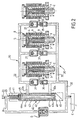
- the transfer pump is schematically illustrated in FIGS. figures 2 , 3 , and 4 and is not shown in detail because it is known and not the subject of the present invention.
- the oil is reciprocated back and forth by hollow pistons 1. These pistons are reciprocated because they are supported by their head 2 on a swash plate. This swash plate is not shown because it is a known means.
- a piston 1 moves (upwards on the Figure 2 ) in its cylinder 4, the oil raises the valve 5.
- a deformable member 9, bellows-shaped is sealingly attached at one end 6 to the support of the cylinder 4 and at its other end 8 to the valve 5.
- the piston 1 moves in the opposite direction the valve 5 is lowered.
- the reciprocating movements of the oil cause a movement back and forth of said valve 5 and therefore of elongations and contractions of the bellows 9.
- the bellows 9 is placed in a chamber filled with gasoline. This room is not represented because such an arrangement is known. The extensions and contractions of the bellows 9 cause a pumping effect.
- Each chamber in which a bellows 9 is deflected comprises a pipe 10 which communicates firstly with the low-pressure circuit 20 by a non-return valve 21 and secondly with the high-pressure circuit 32 by a non-return valve 31 .
- An upstream control of the gasoline flow is used by regulating the flow of gasoline arriving at the pump P by means of a solenoid valve 40 disposed on the pipe 23 coming from the low pressure pump B and distributing the gasoline to the circuit. supply 20 of said pump P by a pipe 22a.
- the present invention is to use this disadvantage by using internal leakage of solenoid valve 40 to solve the problems discussed above.
- the solenoid valve 40 consists of a body 41 in which is placed a jacket 42 in which slides a slide valve 43 which is subjected on one side to a spring 44 and the other to an electromagnet or motor 45.
- drawer 43 has two peripheral grooves 47 and 46 which are placed in front of one of the inlet 32a of the high-pressure manifold 32, the other of the outlet 22a from the low-pressure to the low-pressure manifold 22.
- the groove 46 is uncovered so that the low-pressure gasoline arriving via the pipe 25 communicates with the pipe 22a through the passage formed between the upper end of the jacket 42 and the groove 46.
- this passage varies according to the position of the slide 43 and thus the flow of low pressure gasoline arriving at the pump is regulated according to the needs of the engine.
- the internal architecture of the solenoid valve 40 is determined so that the leakage rate of the high-pressure gasoline to low pressure (at 47a) is greater than the leakage rate of the low-pressure gasoline upstream of the solenoid valve to low downstream pressure (at 46a).
- the respective dimensions of the spaces 46a and 47a must be determined so that the leakage flow through the space 47a is always greater (and at the equal limit) to the leakage flow through the space 46a.
- a controlled check valve is added to the gate solenoid valve (40-43), which is interposed between the low pressure (BP) upstream and the low pressure (BP) downstream of the solenoid valve.
- a leak control device is added to the high pressure (HP) output of the solenoid valve.
- the non-return valve 50 is controlled by the electromagnet 45 by means of a push rod 51.
- the valve is counter-held in the closed position by a spring 52 bearing on a support 53, provided with orifices 54; this support 53 being in abutment against the slide valve 43 of the solenoid valve 40.
- the solenoid valve 40 In the rest position, the solenoid valve 40 is closed. The ball 50 rests on its seat in a sealed manner and the drawer 43 covers the supply light 42a. The internal leakage of the solenoid valve 40 is contained in the envelope 41 of the drawer 43. This is the "zero flow" position, that is to say the suppression of the flow Q1 + Q2.
- the electromagnet 45 is de-energized, the drawer 43 closes the light 42a and the ball 50 returns to its seat.
- This variant has the advantage of ensuring a real zero flow without leakage of the boost pressure (BP) as is the case in the examples of the figure 2 .
- the figure 4 represents another variant embodiment, in which the same elements bear the same references.
- bypass function which allows, among other things, to bypass the HP pump for a start at BP.
- the engine starter does not rotate fast enough that the high pressure pump can provide sufficient flow to the injectors.
- the gasoline at low pressure coming from the booster pump B via the pipe 23 arrives laterally in the chamber 64 in which the cage 60/61 is located, which closes the return spring 44.
- This chamber 64 has at its upper end an orifice 62 which communicates via a pipe 63 with the rail C and therefore the HP therein.
- the low booster pressure arriving via the pipe 23 enters the chamber 64 of the solenoid valve 40 and communicates through the orifice 62 and the pipe 63 with the rail C. This ensures the by-pass function exposed above; on the other hand it also ensures the discharge function of the common rail C in case of stop.
- the electromagnet 45 pushes the spool 43 and the cage 60/61 closes the orifice 62 and thus the communication between the arrival BP and the rail C. If the flow provided by the pump HP is greater than the rate consumed by the engine (valve leakage for example) the pressure in the HP circuit increases, and an HP rail leak to BP is regulated through the orifice 62. The excess flow is recycled to the BP.
- the abscissa is graduated in percentage of PWM (Pulses Width Modulation) which is the usual control means of a solenoid valve by modifying the width of the pulses arriving at the motor 45.
- PWM Pulses Width Modulation
- Curve (I) represents idling engine consumption: it is therefore constant.
- Curve (II) represents the leakage flow through the solenoid valve: it increases with the PWM (reduction of the drawer / liner cover).
- Curve (III) represents the increase in flow as a function of PWM.
- Curve (IV) represents the pressure required to open valve 60/62 to common rail C as a function of PWM.
- curve (IV) is not represented from 40% of PWM. This means that, beyond this value, the force exerted by spring 44, because of crushing caused by the movement of the drawer (upwards on the figure 4 ) controlled by the motor 45, is such that the valve 60/62 can no longer open, the portion 60 of the cage 60/61 remaining applied against the orifice 62.
- the device according to the invention can be cut off the supply and have a negative flow that returns to the tank and drops the pressure in the common rail C.
- the portion 60 of the cage 60/61 does not rest directly against the orifice 62, but on a seat 65 in which one or more precisely calibrated ducts have been arranged so as to ensure through the seat 65 a permanent leakage calibrated.
- the flow control is much more accurate than the pressure control thus obtaining excellent control of the idle.
- the figure 8 represents an exemplary embodiment of the device diagrammatically shown in FIGS. figures 5 and 6 .
- the solenoid valve comprises a drawer 100 (corresponding to the drawer 43) which is actuated by a motor 101 (corresponding to 45).
- the upstream LP coming from the tank through the booster pump, arrives via the pipe 102 (corresponding to 23), in a chamber 103 (corresponding to 64).
- the downstream LP from the internal leak is collected in the groove 104 (corresponding to 46) and is directed to the inlet of the HP pump via the line 105 (corresponding to 22a).
- the internal leakage of the upstream BP to the downstream LP occurs in the area referenced 106 between the chamber 103 and the groove 104.
- the drawer is counter-held by a spring 107 (corresponding to the spring 44) which is in the chamber 103 .
- the spring 107 is disposed between the slide 100 and a pusher 108 carrying a ball 109 which closes a small pipe 110 which opens into a pipe 111 which communicates with the common rail C.
- the pipes 110 and 111 are formed through a part 112 which is fixed to the liner 114 (corresponding to 42) in which the drawer 100 slides.
- the piece 112 is attached to the end of the sleeve 114 by providing a calibrated passage 113 permitting permanent leakage.
- the pipe 111 and the calibrated leak 113 open into a chamber 115 which, via a pipe 116 (corresponding to 63), communicates with the common rail C.
- the ball 109 on its seat of the pipe 110 and the calibrated passage 113 correspond to the valve 60/62 and the leak 65 of the figure 6 .
Landscapes
- Engineering & Computer Science (AREA)
- Chemical & Material Sciences (AREA)
- Combustion & Propulsion (AREA)
- Mechanical Engineering (AREA)
- General Engineering & Computer Science (AREA)
- Physics & Mathematics (AREA)
- Electromagnetism (AREA)
- Fuel-Injection Apparatus (AREA)
- High-Pressure Fuel Injection Pump Control (AREA)
- Control Of The Air-Fuel Ratio Of Carburetors (AREA)
Claims (10)
- Verfahren zur Regelung der Hochdruckversorgung (HP) einer Baugruppe von Einspritzdüsen, die an eine gemeinsame, als "Common Rail" (C) bezeichnete Hochdruckkammer in einem Kreislauf zur Kraftstoffdirekteinspritzung, bezeichnet als I.D.E., über eine Hochdruckpumpe (P) angeschlossen sind, durch Einwirken auf die Niederdruckversorgung (BP) dieser Pumpe (P) mittels eines Magnetschieberventils (E), das durch den Betriebsrechner des Motors gesteuert wird, wobei das Magnetventil (E) eine interne Leckage vom Niederdruck stromaufwärts, der am Magnetventil (E) ankommt, zum Niederdruck stromabwärts hin, der zur Pumpe (P) geht, umfaßt, dadurch gekennzeichnet, daß man in dem Magnetventil (E) eine Leckage von Kraftstoff bei hohem Druck (HP), der im Common Rail (C) vorliegt, zum Niederdruck stromaufwärts vorsieht.
- Verfahren nach Anspruch 1, bestehend im Anschluß der Kammer (64) des Magnetventils (E), welche den Niederdruck stromaufwärts aufnimmt, an den Common Rail (C) durch Mittel, welche die Funktion von Rückschlagventilen und eines kalibrierten Durchlasses erfüllen, derart, daß bei bestimmten Funktionszuständen des Motors der Kraftstoff, der sich auf hohem Druck in dem Common Rail befindet, in die Niederdruckzufuhr stromaufwärts zurückgefördert werden kann.
- Vorrichtung zum Regeln der Kraftstoffversorgung eines Motors mit Direkteinspritzung, zur Durchführung des Verfahrens nach Anspruch 2, der Art, mit
einer Niederdruck-Kraftstoffversorgung durch eine Pumpe (B), die aus einem Vorratsbehälter (R) fördert, einer Hochdruck-Pumpe (P), die einen Common Rail (C) versorgt, und mit einem Magnetventil (E), das die Niedrigdruck-Kraftstoffversorgung der Pumpe (P) regelt, wobei das Magnetventil (E) ein Magnet-Schieberventil (40) ist, das in einer Führung (42) derart gleitet, daß es die Niederdruck-Zufuhr stromaufwärts (23) mit der Leitung niedrigen Drucks stromabwärts (22a), welche die Pumpe (P) versorgt, unter Zwischenschaltung einer im Schieber (43) ausgebildeten Auskehlung (46) verbindet, wobei zwischen dem Niedrigdruck stromaufwärts (23) und dem Niedrigdruck stromabwärts (22a) ein Leckagedurchsatz mittels eines Spiels zwischen der Buchse (42) und dem Schieber (43) eingerichtet ist, dadurch gekennzeichnet, daß der Schieber (43) von einem Motor (45) bewegt und von einer Feder (44) gegengespannt wird, wobei letztere in einem deformierbaren Käfig (60, 61) aufgenommen ist, der in einer Kammer (64) sitzt, in welche die Zufuhrleitung (23) für den stromaufwärtigen Niedrigdruck mündet, wobei der obere Abschnitt (60) dieses Käfigs eine Öffnung (62) der Kammer (64) verschließt oder öffnet, die durch eine Leitung (63) an den Common Rail (C) angeschlossen ist, wobei dieses Verschließmittel außerdem mit kalibrierten Öffnungen (65) derart versehen ist, daß in Abhängigkeit vom Motorbedarf eine Verbindung zwischen dem Vorratsbehälter (R) und dem Common Rail (C) über die Leitungen (23) und (63) durch die Öffnung (62) und/oder die kalibrierten Öffnungen (65) hergestellt werden kann. - Vorrichtung nach Anspruch 3, bei der die Öffnung (62) einen Sitz (65) umfaßt, gegen den der bewegliche Abschnitt (60) des deformierbaren Käfigs (60/61) zur Anlage kommt, wobei der Sitz (65) von einer oder mehreren kalibrierten Leitungen durchlaufen wird, derart, daß durch den Sitz (65) hindurch eine laufende kalibrierte Leckage gewährleistet ist.
- Vorrichtung nach Anspruch 3, bei welcher der Schieber (43) des Magnetventils (E) von einer Bohrung (48) durchsetzt wird.
- Vorrichtung nach Anspruch 4, die derart ausgestaltet ist, daß bei Normalbetrieb des Motors der Kraftstoff bei niedrigem Druck, der von der Niederdruckpumpe (B) geliefert wird, das Magnetventil durchläuft, indem er durch die Auskehlung (46) fließt, die mehr oder weniger verdeckt wird durch die Bewegung des Schiebers (43), der vom Motor (45) bewegt wird, entgegen der Feder (44), die den Abschnitt (60) des Käfigs gegen die Öffnung (62) anlegt.
- Vorrichtung nach Anspruch 3, die derart ausgebildet ist, daß bei Stillstand des Motors der im Common Rail (C) verbleibende Resthochdruck sich in den Vorratsbehälter (R) durch die kalibrierten Öffnungen (65), die Kammer (64) und die Leitung (23) entleert.
- Vorrichtung nach Anspruch 3, die derart ausgebildet ist, daß bei Bremsbetrieb des Motors die Einspritzdüsen geschlossen sind, jedoch die Pumpe (P) weiter angetrieben wird und den vom Niedrigdruck stromaufwärts zum Niedrigdruck stromabwärts gerichteten Leckagefluß pumpt, wobei der Hochdruck im Common Rail ansteigt und den Käfig (60) unter Freigabe der Öffnung (62) derart zurückdrückt, daß er zum Vorratsbehälter (R) zurückgeführt wird.
- Vorrichtung nach Anspruch 3, die derart ausgebildet ist, daß, wenn der Motor beim Verlangsamen dreht, der Kraftstoffüberschuß hohen Drucks, der von der Pumpe (P) geliefert wird, zum Vorratsbehälter (R) durch die Leitung (63), die Öffnung (62) und die Leitung (23) zurückgefördert wird.
- Vorrichtung nach einem der Ansprüche 3 bis 9, die zum Regeln der Niederdruck-Kraftstoffversorgung (BP) folgendes umfaßt:- ein Magnetventil (40), dessen Schieber (43-100) von einem Motor (45-100) betrieben wird;- der Niederdruck (BP), der am Magnetventil über Leitungen (23-102) ankommt, mündet in eine Kammer (64-103), in der sich eine gegen den Schieber (43-100) wirkende Feder (44-107) befindet, und wird an die Pumpe (P) durch eine Leitung (23a-105) angelegt,wobei die innere Leckage des Niedrigdruckes stromaufwärts zum Niedrigdruck stromabwärts hin, die sich zwischen der Kammer (64-103) und dem Common Rail (C) einstellt, über ein Ventil (60/61-110), das von den Bewegungen des Schiebers (48-108) gesteuert wird, mit Zusatz eines kalibrierten Leckageflusses erfolgt und eine Verbindung zwischen dem Hochdruck (HP) und dem Niedrigdruck (BP) stromaufwärts zuläßt, sei es durch dieses Ventil (60/61) hindurch oder seitlich desselben durch eine kalibrierte Öffnung (113).
Applications Claiming Priority (5)
| Application Number | Priority Date | Filing Date | Title |
|---|---|---|---|
| FR0208726 | 2002-07-11 | ||
| FR0208726 | 2002-07-11 | ||
| FR0209797 | 2002-07-31 | ||
| FR0209797 | 2002-07-31 | ||
| PCT/FR2003/002118 WO2004007950A2 (fr) | 2002-07-11 | 2003-07-08 | Dispositif de controle de debit d'une pompe a injection directe d'essence |
Publications (2)
| Publication Number | Publication Date |
|---|---|
| EP1521913A2 EP1521913A2 (de) | 2005-04-13 |
| EP1521913B1 true EP1521913B1 (de) | 2009-09-09 |
Family
ID=30117025
Family Applications (1)
| Application Number | Title | Priority Date | Filing Date |
|---|---|---|---|
| EP03755583A Expired - Lifetime EP1521913B1 (de) | 2002-07-11 | 2003-07-08 | Vorrichtung und Verfahren zur Regelung der Liefermenge einer Pumpe zur Benzindirekteinspritzung |
Country Status (7)
| Country | Link |
|---|---|
| US (1) | US7270113B2 (de) |
| EP (1) | EP1521913B1 (de) |
| JP (1) | JP4441608B2 (de) |
| AT (1) | ATE442524T1 (de) |
| AU (1) | AU2003273426A1 (de) |
| DE (1) | DE60329182D1 (de) |
| WO (1) | WO2004007950A2 (de) |
Families Citing this family (10)
| Publication number | Priority date | Publication date | Assignee | Title |
|---|---|---|---|---|
| FR2858432B1 (fr) * | 2003-08-01 | 2005-10-07 | Eaton Corp | Electrovanne de regulation de debit et de pression |
| DE102005020686B4 (de) * | 2005-05-03 | 2007-08-02 | Siemens Ag | Verfahren und Vorrichung zum Steuern einer Kraftstoffzuführeinrichtung einer Brennkraftmaschine |
| ITPD20060126A1 (it) * | 2006-04-05 | 2007-10-06 | Omvl Srl | Dispositivo di controllo della erogazione di un gas combustibile in motori a combustione interna. |
| FR2903456B1 (fr) * | 2006-07-07 | 2008-10-17 | Siemens Automotive Hydraulics | Pompe transfert a plusieurs pistons |
| US7789070B2 (en) | 2008-03-27 | 2010-09-07 | Ford Global Technologies, Llc | In-line electro-mechanical modulating device to modulate fuel flow in fuel rails to reduce noise |
| US8291889B2 (en) | 2009-05-07 | 2012-10-23 | Caterpillar Inc. | Pressure control in low static leak fuel system |
| DE102010064171A1 (de) * | 2010-12-27 | 2012-06-28 | Robert Bosch Gmbh | Druckregelanordnung eines Kraftstoffversorgungssystems |
| FR3021359B1 (fr) * | 2014-05-26 | 2019-06-07 | Safran Power Units | Dispositif et procede de prechauffage de carburant dans une turbomachine |
| FR3056644B1 (fr) | 2016-09-23 | 2018-11-02 | Continental Automotive France | Procede de commande d'une pompe a carburant pour un vehicule automobile |
| CN115126637B (zh) * | 2022-07-20 | 2024-02-20 | 潍柴动力股份有限公司 | 一种高压共轨燃油系统及汽车 |
Family Cites Families (12)
| Publication number | Priority date | Publication date | Assignee | Title |
|---|---|---|---|---|
| DE3345391C2 (de) * | 1983-12-15 | 1994-05-26 | Bosch Gmbh Robert | Einrichtung zur temperaturabhängigen Umschaltung der Überströmmenge einer Diesel-Einspritzpumpe |
| JP3115099B2 (ja) * | 1992-04-13 | 2000-12-04 | 株式会社小野測器 | 燃費計測装置 |
| DE19539883B4 (de) | 1995-05-26 | 2011-06-01 | Robert Bosch Gmbh | Kraftstoffversorgungsanlage und Verfahren zum Betreiben einer Brennkraftmaschine |
| DE19612413B4 (de) | 1996-03-28 | 2006-06-29 | Siemens Ag | Druckfluid-Versorgungssystem, insbesondere für ein Kraftstoff-Einspritzsystem |
| DE19627741A1 (de) * | 1996-07-10 | 1998-01-15 | Mannesmann Vdo Ag | Druckhalteeinrichtung |
| DE19714489C1 (de) | 1997-04-08 | 1998-10-01 | Siemens Ag | Einspritzsystem, Druckventil und Volumenstromregelventil und Verfahren zum Regeln eines Kraftstoffdruckes |
| DE19737125C2 (de) | 1997-08-26 | 2002-01-31 | Siemens Ag | Volumenstrom-Regelvorrichtung und Einspritzsystem mit einer solchen Regelvorrichtung |
| JP3999855B2 (ja) * | 1997-09-25 | 2007-10-31 | 三菱電機株式会社 | 燃料供給装置 |
| DE19853103A1 (de) * | 1998-11-18 | 2000-05-25 | Bosch Gmbh Robert | Kraftstoffeinspritzsystem für Brennkraftmaschinen |
| JP2000291509A (ja) * | 1999-04-01 | 2000-10-17 | Mitsubishi Electric Corp | 直噴式ガソリンエンジン用燃料供給装置 |
| DE10058674A1 (de) | 2000-11-25 | 2002-06-06 | Bosch Gmbh Robert | Verfahren, Computerprogramm und Steuer und/oder Regelgerät zum Betreiben einer Brennkraftmaschine |
| JP3823060B2 (ja) * | 2002-03-04 | 2006-09-20 | 株式会社日立製作所 | 高圧燃料供給ポンプ |
-
2003
- 2003-07-08 WO PCT/FR2003/002118 patent/WO2004007950A2/fr not_active Ceased
- 2003-07-08 DE DE60329182T patent/DE60329182D1/de not_active Expired - Fee Related
- 2003-07-08 US US10/520,918 patent/US7270113B2/en not_active Expired - Fee Related
- 2003-07-08 AU AU2003273426A patent/AU2003273426A1/en not_active Abandoned
- 2003-07-08 EP EP03755583A patent/EP1521913B1/de not_active Expired - Lifetime
- 2003-07-08 JP JP2004520737A patent/JP4441608B2/ja not_active Expired - Fee Related
- 2003-07-08 AT AT03755583T patent/ATE442524T1/de not_active IP Right Cessation
Also Published As
| Publication number | Publication date |
|---|---|
| ATE442524T1 (de) | 2009-09-15 |
| JP2005538285A (ja) | 2005-12-15 |
| DE60329182D1 (de) | 2009-10-22 |
| US7270113B2 (en) | 2007-09-18 |
| JP4441608B2 (ja) | 2010-03-31 |
| WO2004007950A3 (fr) | 2004-04-08 |
| AU2003273426A1 (en) | 2004-02-02 |
| US20050252492A1 (en) | 2005-11-17 |
| AU2003273426A8 (en) | 2004-02-02 |
| WO2004007950A2 (fr) | 2004-01-22 |
| EP1521913A2 (de) | 2005-04-13 |
Similar Documents
| Publication | Publication Date | Title |
|---|---|---|
| EP2486262B1 (de) | Schaltung zur zuführung von kraftstoff an ein flugzeugtriebwerk | |
| CA2776314C (fr) | Circuit d'alimentation en carburant d'un moteur d'aeronef | |
| EP4256189B1 (de) | Flugzeugturbinentriebwerkanordnung mit einem passiven ventil zum bypass eines brennstoff-öl-wärmetauschers | |
| FR2750173A1 (fr) | Injecteur de carburant pilote hydrauliquement par une vanne de commande directe a aiguille | |
| FR2741395A1 (fr) | Systeme hydraulique d'injection de carburant a remplissage dose et procede d'injection de carburant | |
| FR2901323A1 (fr) | Systeme d'injection a rampe commune | |
| EP0995031B1 (de) | Kraftstoffeinspritzvorrichtung für dieselmotoren | |
| FR2925594A1 (fr) | Systeme de regulation d'une turbomachine | |
| FR2704600A1 (fr) | Installation d'injection de carburant pour moteur thermique. | |
| FR2819020A1 (fr) | Installation d'injection de carburant | |
| FR2919022A1 (fr) | Centrale hydraulique pour moteur a taux de compression variable. | |
| WO2015185856A1 (fr) | Système d'alimentation de turbomachine en fluide avec un ensemble de pompage basse pression comprenant deux pompes en parallèle | |
| EP1521913A2 (de) | Vorrichtung zur regelung der liefermenge einer pumpe zur benzindirekteinspritzung | |
| FR2910938A1 (fr) | Systeme d'alimentation en carburant notamment du type rampe commune pour un moteur a combustion interne | |
| EP1999372A1 (de) | Förderpumpe zur hochdruckbenzineinspritzung | |
| EP0898649B1 (de) | Flüssigkraftstoffeinspritzvorrichtung für verbrennungsmotor | |
| FR2771454A1 (fr) | Injection electronique de carburant a fonctionnement silencieux | |
| FR2828526A1 (fr) | Procede et systeme d'alimentation en carburant d'un moteur a combustion interne, et appareil de commande du procede | |
| FR2817297A1 (fr) | Systeme d'injection de carburant dans un moteur a combustion interne | |
| FR2755188A1 (fr) | Injecteur de carburant actionne hydrauliquement avec acces de stabilisation de ralenti | |
| EP1748194A1 (de) | Vorrichtung zur Erhöhung des Druckes für eine hydraulische Verstelleinrichtung in einer Brennkraftmaschine und Brennkraftmaschine mit einer solchen Einrichtung | |
| FR2768185A1 (fr) | Installation d'injection de carburant pour un moteur a combustion interne | |
| FR3122220A1 (fr) | Système d'alimentation en carburant liquide pour un moteur d’aéronef | |
| FR2889259A3 (fr) | Rampe commune d'alimentation en carburant pour vehicule a pression variable | |
| FR2752268A1 (fr) | Dispositif d'amelioration de la dynamique d'injection de combustible pour les moteurs diesel equipes de pompes d'injection a debit pulse |
Legal Events
| Date | Code | Title | Description |
|---|---|---|---|
| PUAI | Public reference made under article 153(3) epc to a published international application that has entered the european phase |
Free format text: ORIGINAL CODE: 0009012 |
|
| 17P | Request for examination filed |
Effective date: 20041201 |
|
| AK | Designated contracting states |
Kind code of ref document: A2 Designated state(s): AT BE BG CH CY CZ DE DK EE ES FI FR GB GR HU IE IT LI LU MC NL PT RO SE SI SK TR |
|
| AX | Request for extension of the european patent |
Extension state: AL LT LV MK |
|
| DAX | Request for extension of the european patent (deleted) | ||
| RAP1 | Party data changed (applicant data changed or rights of an application transferred) |
Owner name: CONTINENTAL AUTOMOTIVE ASNIERES FRANCE |
|
| GRAP | Despatch of communication of intention to grant a patent |
Free format text: ORIGINAL CODE: EPIDOSNIGR1 |
|
| RTI1 | Title (correction) |
Free format text: DEVICE AND PROCESS FOR CONTROLLING THE FLOW RATE OF A DIRECT INJECTION FUEL PUMP |
|
| GRAS | Grant fee paid |
Free format text: ORIGINAL CODE: EPIDOSNIGR3 |
|
| GRAA | (expected) grant |
Free format text: ORIGINAL CODE: 0009210 |
|
| AK | Designated contracting states |
Kind code of ref document: B1 Designated state(s): AT BE BG CH CY CZ DE DK EE ES FI FR GB GR HU IE IT LI LU MC NL PT RO SE SI SK TR |
|
| REG | Reference to a national code |
Ref country code: GB Ref legal event code: FG4D Free format text: NOT ENGLISH |
|
| REG | Reference to a national code |
Ref country code: CH Ref legal event code: EP |
|
| REG | Reference to a national code |
Ref country code: IE Ref legal event code: FG4D |
|
| REF | Corresponds to: |
Ref document number: 60329182 Country of ref document: DE Date of ref document: 20091022 Kind code of ref document: P |
|
| PG25 | Lapsed in a contracting state [announced via postgrant information from national office to epo] |
Ref country code: SE Free format text: LAPSE BECAUSE OF FAILURE TO SUBMIT A TRANSLATION OF THE DESCRIPTION OR TO PAY THE FEE WITHIN THE PRESCRIBED TIME-LIMIT Effective date: 20090909 Ref country code: FI Free format text: LAPSE BECAUSE OF FAILURE TO SUBMIT A TRANSLATION OF THE DESCRIPTION OR TO PAY THE FEE WITHIN THE PRESCRIBED TIME-LIMIT Effective date: 20090909 |
|
| NLV1 | Nl: lapsed or annulled due to failure to fulfill the requirements of art. 29p and 29m of the patents act | ||
| PG25 | Lapsed in a contracting state [announced via postgrant information from national office to epo] |
Ref country code: NL Free format text: LAPSE BECAUSE OF FAILURE TO SUBMIT A TRANSLATION OF THE DESCRIPTION OR TO PAY THE FEE WITHIN THE PRESCRIBED TIME-LIMIT Effective date: 20090909 Ref country code: SI Free format text: LAPSE BECAUSE OF FAILURE TO SUBMIT A TRANSLATION OF THE DESCRIPTION OR TO PAY THE FEE WITHIN THE PRESCRIBED TIME-LIMIT Effective date: 20090909 |
|
| PG25 | Lapsed in a contracting state [announced via postgrant information from national office to epo] |
Ref country code: CY Free format text: LAPSE BECAUSE OF FAILURE TO SUBMIT A TRANSLATION OF THE DESCRIPTION OR TO PAY THE FEE WITHIN THE PRESCRIBED TIME-LIMIT Effective date: 20090909 |
|
| REG | Reference to a national code |
Ref country code: IE Ref legal event code: FD4D |
|
| PG25 | Lapsed in a contracting state [announced via postgrant information from national office to epo] |
Ref country code: RO Free format text: LAPSE BECAUSE OF FAILURE TO SUBMIT A TRANSLATION OF THE DESCRIPTION OR TO PAY THE FEE WITHIN THE PRESCRIBED TIME-LIMIT Effective date: 20090909 Ref country code: PT Free format text: LAPSE BECAUSE OF FAILURE TO SUBMIT A TRANSLATION OF THE DESCRIPTION OR TO PAY THE FEE WITHIN THE PRESCRIBED TIME-LIMIT Effective date: 20100111 Ref country code: IE Free format text: LAPSE BECAUSE OF FAILURE TO SUBMIT A TRANSLATION OF THE DESCRIPTION OR TO PAY THE FEE WITHIN THE PRESCRIBED TIME-LIMIT Effective date: 20090909 Ref country code: EE Free format text: LAPSE BECAUSE OF FAILURE TO SUBMIT A TRANSLATION OF THE DESCRIPTION OR TO PAY THE FEE WITHIN THE PRESCRIBED TIME-LIMIT Effective date: 20090909 Ref country code: ES Free format text: LAPSE BECAUSE OF FAILURE TO SUBMIT A TRANSLATION OF THE DESCRIPTION OR TO PAY THE FEE WITHIN THE PRESCRIBED TIME-LIMIT Effective date: 20091220 |
|
| PG25 | Lapsed in a contracting state [announced via postgrant information from national office to epo] |
Ref country code: SK Free format text: LAPSE BECAUSE OF FAILURE TO SUBMIT A TRANSLATION OF THE DESCRIPTION OR TO PAY THE FEE WITHIN THE PRESCRIBED TIME-LIMIT Effective date: 20090909 |
|
| PLBE | No opposition filed within time limit |
Free format text: ORIGINAL CODE: 0009261 |
|
| STAA | Information on the status of an ep patent application or granted ep patent |
Free format text: STATUS: NO OPPOSITION FILED WITHIN TIME LIMIT |
|
| PG25 | Lapsed in a contracting state [announced via postgrant information from national office to epo] |
Ref country code: DK Free format text: LAPSE BECAUSE OF FAILURE TO SUBMIT A TRANSLATION OF THE DESCRIPTION OR TO PAY THE FEE WITHIN THE PRESCRIBED TIME-LIMIT Effective date: 20090909 |
|
| 26N | No opposition filed |
Effective date: 20100610 |
|
| PG25 | Lapsed in a contracting state [announced via postgrant information from national office to epo] |
Ref country code: GR Free format text: LAPSE BECAUSE OF FAILURE TO SUBMIT A TRANSLATION OF THE DESCRIPTION OR TO PAY THE FEE WITHIN THE PRESCRIBED TIME-LIMIT Effective date: 20091210 |
|
| BERE | Be: lapsed |
Owner name: CONTINENTAL AUTOMOTIVE ASNIERES FRANCE Effective date: 20100731 |
|
| PG25 | Lapsed in a contracting state [announced via postgrant information from national office to epo] |
Ref country code: MC Free format text: LAPSE BECAUSE OF NON-PAYMENT OF DUE FEES Effective date: 20100731 |
|
| REG | Reference to a national code |
Ref country code: CH Ref legal event code: PL |
|
| GBPC | Gb: european patent ceased through non-payment of renewal fee |
Effective date: 20100708 |
|
| PG25 | Lapsed in a contracting state [announced via postgrant information from national office to epo] |
Ref country code: DE Free format text: LAPSE BECAUSE OF NON-PAYMENT OF DUE FEES Effective date: 20110201 Ref country code: CH Free format text: LAPSE BECAUSE OF NON-PAYMENT OF DUE FEES Effective date: 20100731 Ref country code: LI Free format text: LAPSE BECAUSE OF NON-PAYMENT OF DUE FEES Effective date: 20100731 |
|
| REG | Reference to a national code |
Ref country code: DE Ref legal event code: R119 Ref document number: 60329182 Country of ref document: DE Effective date: 20110201 |
|
| PG25 | Lapsed in a contracting state [announced via postgrant information from national office to epo] |
Ref country code: IT Free format text: LAPSE BECAUSE OF NON-PAYMENT OF DUE FEES Effective date: 20100708 Ref country code: CZ Free format text: LAPSE BECAUSE OF NON-PAYMENT OF DUE FEES Effective date: 20100708 |
|
| PG25 | Lapsed in a contracting state [announced via postgrant information from national office to epo] |
Ref country code: BE Free format text: LAPSE BECAUSE OF NON-PAYMENT OF DUE FEES Effective date: 20100731 |
|
| PG25 | Lapsed in a contracting state [announced via postgrant information from national office to epo] |
Ref country code: GB Free format text: LAPSE BECAUSE OF NON-PAYMENT OF DUE FEES Effective date: 20100708 |
|
| PG25 | Lapsed in a contracting state [announced via postgrant information from national office to epo] |
Ref country code: AT Free format text: LAPSE BECAUSE OF NON-PAYMENT OF DUE FEES Effective date: 20100708 |
|
| PG25 | Lapsed in a contracting state [announced via postgrant information from national office to epo] |
Ref country code: HU Free format text: LAPSE BECAUSE OF FAILURE TO SUBMIT A TRANSLATION OF THE DESCRIPTION OR TO PAY THE FEE WITHIN THE PRESCRIBED TIME-LIMIT Effective date: 20100310 Ref country code: LU Free format text: LAPSE BECAUSE OF NON-PAYMENT OF DUE FEES Effective date: 20100708 Ref country code: BG Free format text: LAPSE BECAUSE OF FAILURE TO SUBMIT A TRANSLATION OF THE DESCRIPTION OR TO PAY THE FEE WITHIN THE PRESCRIBED TIME-LIMIT Effective date: 20090909 |
|
| PG25 | Lapsed in a contracting state [announced via postgrant information from national office to epo] |
Ref country code: TR Free format text: LAPSE BECAUSE OF FAILURE TO SUBMIT A TRANSLATION OF THE DESCRIPTION OR TO PAY THE FEE WITHIN THE PRESCRIBED TIME-LIMIT Effective date: 20090909 |
|
| REG | Reference to a national code |
Ref country code: FR Ref legal event code: PLFP Year of fee payment: 14 |
|
| REG | Reference to a national code |
Ref country code: FR Ref legal event code: PLFP Year of fee payment: 15 |
|
| REG | Reference to a national code |
Ref country code: FR Ref legal event code: PLFP Year of fee payment: 16 |
|
| PGFP | Annual fee paid to national office [announced via postgrant information from national office to epo] |
Ref country code: FR Payment date: 20210727 Year of fee payment: 19 |
|
| PG25 | Lapsed in a contracting state [announced via postgrant information from national office to epo] |
Ref country code: FR Free format text: LAPSE BECAUSE OF NON-PAYMENT OF DUE FEES Effective date: 20220731 |