EP1521947B1 - Röntgenstrahlspektrumsmethode zur fluoreszenzanalyse mit optischen komponenten - Google Patents
Röntgenstrahlspektrumsmethode zur fluoreszenzanalyse mit optischen komponenten Download PDFInfo
- Publication number
- EP1521947B1 EP1521947B1 EP03760459.2A EP03760459A EP1521947B1 EP 1521947 B1 EP1521947 B1 EP 1521947B1 EP 03760459 A EP03760459 A EP 03760459A EP 1521947 B1 EP1521947 B1 EP 1521947B1
- Authority
- EP
- European Patent Office
- Prior art keywords
- ray
- spectrum
- optical component
- analyzer
- scatter
- Prior art date
- Legal status (The legal status is an assumption and is not a legal conclusion. Google has not performed a legal analysis and makes no representation as to the accuracy of the status listed.)
- Expired - Lifetime
Links
Images


Classifications
-
- G—PHYSICS
- G01—MEASURING; TESTING
- G01N—INVESTIGATING OR ANALYSING MATERIALS BY DETERMINING THEIR CHEMICAL OR PHYSICAL PROPERTIES
- G01N23/00—Investigating or analysing materials by the use of wave or particle radiation, e.g. X-rays or neutrons, not covered by groups G01N3/00 – G01N17/00, G01N21/00 or G01N22/00
- G01N23/22—Investigating or analysing materials by the use of wave or particle radiation, e.g. X-rays or neutrons, not covered by groups G01N3/00 – G01N17/00, G01N21/00 or G01N22/00 by measuring secondary emission from the material
- G01N23/223—Investigating or analysing materials by the use of wave or particle radiation, e.g. X-rays or neutrons, not covered by groups G01N3/00 – G01N17/00, G01N21/00 or G01N22/00 by measuring secondary emission from the material by irradiating the sample with X-rays or gamma-rays and by measuring X-ray fluorescence
-
- G—PHYSICS
- G01—MEASURING; TESTING
- G01N—INVESTIGATING OR ANALYSING MATERIALS BY DETERMINING THEIR CHEMICAL OR PHYSICAL PROPERTIES
- G01N2223/00—Investigating materials by wave or particle radiation
- G01N2223/07—Investigating materials by wave or particle radiation secondary emission
- G01N2223/076—X-ray fluorescence
-
- G—PHYSICS
- G21—NUCLEAR PHYSICS; NUCLEAR ENGINEERING
- G21K—HANDLING OF PARTICLES OR IONISING RADIATION NOT OTHERWISE PROVIDED FOR; IRRADIATION DEVICES; GAMMA RAY OR X-RAY MICROSCOPES
- G21K1/00—Arrangements for handling particles or ionising radiation, e.g. focusing or moderating
- G21K1/06—Arrangements for handling particles or ionising radiation, e.g. focusing or moderating using diffraction, refraction or reflection, e.g. monochromators
Definitions
- the present invention is directed to a method of performing standardless quantitative analysis using X-ray fluorescence.
- X-ray fluorescence (XRF) instruments are a standard means of determining information, such as plating thicknesses, composition, and elemental makeup.
- XRF measurement X-rays impinge on a sample, causing its atoms to emit fluorescence radiation.
- An energy or wavelength discriminating X-ray detector records the radiation. The reading is amplified and digitized to be evaluated by measurement and analysis software.
- the raw measurement data is in the form of a fluorescence spectrum that characterizes the test sample.
- the measurement challenge is not necessarily to determine which elements are present in the sample, but rather in what quantity they are present. Consequently, analysis of the spectrum has to focus on the intensity of the fluorescence radiation.
- the Fundamental Parameters Method significantly improves the capability of the XRF instrument.
- the traditional Fundamental Parameters Method results in an evaluation based on mathematical formulation of the elemental physical processes, as opposed to generating an empirical model using calibration standards.
- the Fundamental Parameters Method of analysis of XRF measurements has been used to obtain data with and without capillary optics.
- the Fundamental Parameters Method is limited in its application because it is difficult to use with capillary or other optical components in the beam path.
- the optical component modifies the energy spectrum of the X-ray beam in an unpredictable fashion.
- the X-ray beam modification reduces the accuracy of the method to less than is typically required for successful analysis of XRF measurements.
- the present invention is directed to a method of measuring the transfer function of an X-ray optical component over a wide range of X-ray energies.
- the method includes the steps of:
- the present invention is also directed to a method of improving the accuracy of X-ray quantitative methods in an apparatus where an X-ray optical component is used between the X-ray source and the specimen to be investigated by utilizing the method described above.
- the present invention is further directed to a method of determining the correct incident energy spectrum when optical components are in the beam path of an X-ray fluorescence instrument.
- the method includes the steps of:
- the present invention is additionally directed to a method of standardless quantitative analysis where the correct incident energy spectrum described above is analyzed using the Fundamental Parameters Method to determine the composition and elemental makeup of a sample.
- X-ray fluorescence refers to spectra obtained by impinging X-rays on a sample, causing its atoms to emit fluorescence radiation, which is subsequently measured by a detector and recorded as count intensity as a function of energy.
- X-ray absorption fine structure refers to the small modulations in the X-ray absorption of an element, comprising about 4% of the total absorption, and caused by the aggregate effect of nearby atoms when the element is in solid form, whether by itself or in combination with other elements.
- X-ray absorption near edge structure refers to the increases and decreases in the X-ray absorption of an element within about 50 electron volts of the X-ray absorption edges of the element, caused by the particular chemical environment of the element.
- the term "theoretical standards” refers to reference standards used for calibration of an analytical instrument which are produced from mathematical models rather than measurements.
- the term "theoretical influence coefficients” refers to mathematical coefficients, which quantify the effect on the X-ray intensity of an element due to other elements and which are obtained from mathematical models without any measurements.
- the present invention provides a method of measuring the transfer function of an X-ray optical component over a wide range of X-ray energies including the steps of:
- Suitable optical components include, but are not limited to, X-ray optical components, such as a monocapillary, a polycapillary bundle, a monolithic polycapillary, a reflective surface, a diffraction element, and an X-ray optical component which modifies the exciting or input spectrum generated by an X-ray source.
- X-ray optical components such as a monocapillary, a polycapillary bundle, a monolithic polycapillary, a reflective surface, a diffraction element, and an X-ray optical component which modifies the exciting or input spectrum generated by an X-ray source.
- the transfer function is used to characterize the influence of an X-ray optical component on the exciting spectrum of an apparatus.
- an X-ray optical component When an X-ray optical component is used, it can be contained or used within or as part of any suitable apparatus. Suitable apparatus that can include the X-ray optical component include, but are not limited to, an X-ray fluorescence analyzer, an X-ray diffraction analyzer, an X-ray absorption analyzer, and an X-ray transmission analyzer.
- An embodiment of the present invention is directed to a method for improving the accuracy of X-ray quantitative methods in an apparatus where an X-ray optical component is used between the X-ray source and the specimen to be investigated.
- the method includes the steps of (a) determining a transfer function for the X-ray optical component as described above; and (b) applying the transfer function to the incident X-ray spectra used in a quantitative method to obtain a corrected incident spectra.
- Suitable X-ray quantitative methods include, but are not limited to, the fundamental parameters method, X-ray absorption spectroscopy, X-ray absorption fine structure, X-ray absorption near edge structure, X-ray diffraction, X-ray transmission, and a standardless method.
- the X-ray quantitative method uses theoretical standards for calibration based on knowledge of the exciting X-ray spectrum from the X-ray source.
- the X-ray quantitative method uses theoretical influence coefficients calculated using knowledge of the exciting X-ray spectrum.
- the X-ray quantitative method comprises a method that relies on knowledge of the exciting X-ray spectrum.
- the inventive method is used as part of a method of measuring the thickness of a coating on a substrate.
- the step of correcting the incident X-ray spectra can be used to determine the thickness of a coating film.
- the inventive method is used as part of a method of performing a compositional analysis of a sample.
- the step of correcting the incident X-ray spectra can be used to perform a compositional analysis of a sample.
- the method of the present invention is used to determine the correct incident energy spectrum when optical components, such as capillary or other optics, are in the beam path of X-ray fluorescence (XRF) instruments.
- the method is especially useful in analyzing XRF measurements via the Fundamental Parameters Method.
- the present method further improves the analytical accuracy of standardless quantitative analysis and facilitates instrument adjustment and calibration when optical components are changed.
- the Fundamental Parameters Method uses a data file of X-ray absorption coefficients, fluorescence yields, and other "fundamental" parameters of various elements of interest in well-established equations that model the fluorescence process.
- the spectrum of X-rays emitted from a sample is analyzed in order to quantify the composition of the material whose X-ray lines were measured.
- the different elements in the sample have different X-ray absorption properties, and so the line intensity for an element will be affected by the concentrations of all elements present in the sample.
- the Fundamental Parameters Method is able to identify and provide relative ratios of the elements in a sample.
- a number of optical components may be used in XRF spectrometers between the X-ray tube and the sample to condition the beam incident on the sample.
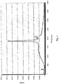
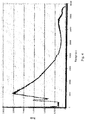
- the energy response of one or more of these optical components is determined by a transfer function at several energies. This function can be measured via scatter from a light element plate (such as a paraffin wax block) in place of the sample. When the scatter measurement is made over the entire operating energy range, both with (see Fig. 3 ) and without (see Fig. 2 .) the optical component in place, and calculating the ratio as a function of energy (see Fig.
- the proper transfer function can be obtained for any optical component.
- the transfer function may then be used, for example, to more accurately determine the spectral characteristics of the X-ray beam incident on the sample.
- the incident spectrum may be used for analyzing measurements made with XRF instruments to obtain, for example, accurate compositions of the samples under investigation or determining optimum excitation conditions to be used for a particular type of sample.
- a depiction of the present method is shown in Fig. 1 .
- FIG. 1 An example of an embodiment of the present invention is shown in Fig. 1 , where an X-ray tube 10 emits an X-ray beam 18 (incident beam) in the general direction of a scatter block 16.
- X-ray beam 18 passes through an optical component 12, impinges on scatter block 16, and forms a scatter pattern 20.
- the scatter pattern 20 is measured over the entire operating energy range by detector 14.
- the scatter measurement is made over the entire operating energy range, with ( Fig. 3 ) and without ( Fig. 2 ) the optical component in place, and a ratio is calculated as a function of energy as shown in Fig. 4 .
- the transfer function ( Fig. 1 )
- Fig. 4 is then applied at any given operating energy, with the optical component in place, to more accurately determine the spectral characteristics of the X-ray beam incident on the sample.
- An accurate composition of the sample can be determined from the corrected incident spectra and application of the Fundamental Parameters Method.
- the transfer function in Fig. 4 which is applied to the incident beam, is the ratio of the spectra in Fig. 2 to the spectra in Fig. 3 .
- An embodiment of the present invention includes a method of measuring the energy response transfer function of capillary or other optical components in the X-ray beam path rather than applying empirical estimates of correction factors or requiring measurements of the direct incident beam.
- a further embodiment of the present invention facilitates determination of the correct incident X-ray spectra for any optical component placed between the X-ray tube and a sample. Further, the present invention improves the accuracy of the standardless Fundamental Parameters Method when used with capillary optics to better than 1%.
- the geometric arrangement of the spectrometer does not need to be reconfigured to measure the incident beam. There is no need to determine empirical factors to correct calculations on concentrations for different sample types.
- the present method may be used without any empirically measured correction factors and over a wide variety of measurement conditions and sample compositions without recalibration or remeasurement of the optical component transfer function.
- the method of the present invention provides improved efficiency by applying a transfer function determined at a maximum operating energy range over the entire operating range. This is a marked improvement over prior art attempts to use the Fundamental Parameters Method with optical components, which required the use of a large number of empirical correction factors that were determined via the use of standard samples. In prior art methods, the sensitivity factors were adjusted, but the correct excitation spectra was not calculated. Further, in prior methods, new empirical correction factors were needed for each measurement condition and sample matrix. The present invention solves these problems because the inventive method may be used without any empirically measured correction factors and over a wide variety of measurement conditions and sample compositions without recalibration or remeasurement of the optical component transfer function.
Landscapes
- Physics & Mathematics (AREA)
- Health & Medical Sciences (AREA)
- Life Sciences & Earth Sciences (AREA)
- Chemical & Material Sciences (AREA)
- Analytical Chemistry (AREA)
- Biochemistry (AREA)
- General Health & Medical Sciences (AREA)
- General Physics & Mathematics (AREA)
- Immunology (AREA)
- Pathology (AREA)
- Analysing Materials By The Use Of Radiation (AREA)
Claims (20)
- Verfahren zum Messen der Transferfunktion in Bezug auf die Strahlungsenergie einer optischen Röntgenkomponente über einen großen Bereich von Röntgenenergien, Folgendes umfassend:Verwenden einer optischen Röntgenkomponente zwischen einer Röntgenquelle und einem Streuziel, um ein erstes Streuspektrum zu erhalten;Erhalten eines zweiten Streuspektrums aus dem gleichen oder einem ähnlichen Ziel ohne die optische Röntgenkomponente zwischen der Röntgenquelle und dem Streuziel; undBerechnen der Transferfunktion durch das Verhältnis des ersten Streuspektrums zu dem zweiten Streuspektrum.
- Verfahren nach Anspruch 1, wobei die optische Röntgenkomponente aus der Gruppe ausgewählt ist, welche aus Kollimatoren, Blenden, Kapillaroptik, Filtern, einer Monokapillare, einem Polykapillarbündel, einer monolithischen Polykapillare, einer reflektierenden Oberfläche, einem Beugungselement und einer optischen Röntgenkomponente besteht, welche das Anregungs- oder Eingangsspektrum modifiziert, welches durch die Röntgenquelle erzeugt wird.
- Verfahren nach Anspruch 1, wobei das Verhältnis verwendet wird, um den Einfluss der optischen Röntgenkomponente auf das Anregungsspektrum der Vorrichtung zu charakterisieren.
- Verfahren nach Anspruch 1, wobei die optische Röntgenkomponente innerhalb einer Vorrichtung enthalten ist, welche aus der Gruppe ausgewählt ist, welche aus einem Röntgenfluoreszenzanalysator, einem Röntgenbeugungsanalysator, einem Röntgenabsorptionsanalysator und einem Röntgenübertragungsanalysator besteht.
- Verfahren zum Verbessern der Genauigkeit von quantitativen Röntgenverfahren in einer Vorrichtung, in welcher eine optische Röntgenkomponente zwischen der Röntgenquelle und der Probe, welche untersucht werden soll, verwendet wird, das Verfahren Folgendes umfassend:(a) Bestimmen der Transferfunktionsterme der Strahlungsenergie für die optische Röntgenkomponente nach Anspruch 1;(b) Erhalten des einfallenden Spektrums über einen gegebenen Energiebereich ohne die angeordnete optische Komponente; und(c) Korrigieren des einfallenden Spektrums in (b) durch Anwenden der Transferfunktion in (a), um das korrekte einfallende Energiespektrum für das Instrument mit der angeordneten optischen Komponente zu erzeugen.
- Verfahren nach Anspruch 5, wobei die Vorrichtung aus der Gruppe ausgewählt ist, welche aus einem Röntgenfluoreszenzanalysator, einem Röntgenbeugungsanalysator, einem Röntgenabsorptionsanalysator und einem Röntgenübertragungsanalysator besteht.
- Verfahren nach Anspruch 5, wobei das quantitative Röntgenverfahren aus der Gruppe ausgewählt ist, welche aus dem Grundparameterverfahren, der Röntgenabsorptionsspektroskopie, der Feinstruktur-Röntgenabsorption, der Randstruktur-Röntgenabsorption, der Röntgenbeugung, der Röntgenübertragung und einem ungenormten Verfahren besteht.
- Verfahren nach Anspruch 5, wobei das quantitative Röntgenverfahren theoretische Normen zur Kalibrierung auf der Grundlage des Wissens über das Anregungsröntgenspektrum aus der Röntgenquelle verwendet.
- Verfahren nach Anspruch 8, wobei das quantitative Röntgenverfahren theoretische Einflusskoeffizienten unter Verwendung des Wissens über das Anregungsröntgenspektrum verwendet.
- Verfahren nach Anspruch 8, wobei das quantitative Röntgenverfahren ein Verfahren umfasst, welches auf dem Wissen über das Anregungsröntgenspektrum beruht.
- Verfahren zum Messen der Beschichtungsdicke eines Beschichtungsfilms, welches das Verfahren nach Anspruch 5 umfasst.
- Verfahren zum Durchführen einer qualitativen Analyse einer Probe, welches das Verfahren nach Anspruch 5 umfasst.
- Verfahren nach Anspruch 5, weiterhin den Schritt des Analysierens der korrigierten Röntgenspektren umfassend, um die Dicke eines Beschichtungsfilms zu bestimmen.
- Verfahren nach Anspruch 5, weiterhin den Schritt des Analysierens der korrigierten Röntgenspektren umfassend, um eine qualitative Analyse einer Probe durchzuführen.
- Verfahren zum Bestimmen eines korrekt einfallenden Energiespektrums aus einem Röntgenfluoreszenzinstrument, wenn eine oder mehrere optische Komponenten in dem Röntgenstrahlweg sind, das Verfahren Folgendes umfassend:(a) Bestimmen einer Transferfunktion in Bezug auf Strahlungsenergie für jede optische Komponente durch:(i) Durchführen von Streumessungen über einen maximalen Betriebsenergiebereich mit jeder angeordneten optischen Komponente;(ii) Durchführen einer Streumessung über den maximalen Betriebsenergiebereich in (i) ohne eine angeordnete optische Komponente; und(iii)Berechnen der Transferfunktion für jede optische Komponente durch das Verhältnis einer Streuspektrumsintensität in (ii) zu dem Streuspektrum in (i) als eine Funktion der Energie;(b) Erhalten eines einfallenden Spektrums über einen gegebenen Energiebereich ohne die angeordnete optische Komponente; und(c) Korrigieren des einfallenden Spektrums in (b) durch Anwenden einer oder mehrerer der Transferfunktionen in (a), um das korrekte einfallende Energiespektrum für das Instrument mit einer oder mehreren angeordneten optischen Komponenten zu erzeugen.
- Verfahren nach Anspruch 15, wobei die optischen Komponenten aus der Gruppe ausgewählt sind, welche aus Kollimatoren, Blenden, Kapillaroptik, Filtern, einer Monokapillare, einem Polykapillarbündel, einer monolithischen Polykapillare, einer reflektierenden Oberfläche, einem Beugungselement und einer optischen Röntgenkomponente besteht, welche das Anregungs- oder Eingangsspektrum modifiziert, welches durch die Röntgenquelle erzeugt wird.
- Verfahren nach Anspruch 15, wobei das Röntgenfluoreszenzinstrument aus der Gruppe ausgewählt ist, welche aus einem Röntgenfluoreszenzanalysator, einem Röntgenbeugungsanalysator, einem Röntgenabsorptionsanalysator und einem Röntgenübertragungsanalysator besteht.
- Verfahren einer ungenormten quantitativen Analyse einer Probe, Folgendes umfassend:(A) Bestimmen eines korrekt einfallenden Energiespektrums aus einem Röntgenfluoreszenzinstrument, wenn eine oder mehrere optische Komponenten in dem Röntgenstrahlweg sind, das Verfahren Folgendes umfassend:(a) Bestimmen einer Transferfunktion in Bezug auf die Strahlungsenergie für jede optische Komponente durch;(i) Durchführen von Streumessungen über einen maximalen Betriebsenergiebereich mit jeder angeordneten optischen Komponente;(ii) Durchführen einer Streumessung über den maximalen Betriebsenergiebereich in (i) ohne eine angeordnete optische Komponente; und(iii)Berechnen der Transferfunktion für jede optische Komponente durch das Verhältnis einer Streuspektrumsintensität in (ii) zu dem Streuspektrum in (i) als eine Funktion der Energie;(b) Korrigieren eines einfallenden Spektrums, welches unter Verwendung eines Grundparameterverfahrens berechnet wurde, durch Anwenden einer oder mehrerer der Transferfunktionen in (a), um das korrekte einfallende Energiespektrum für das Instrument mit einer oder mehreren angeordneten optischen Komponenten zu erzeugen; und(B) Erhalten des Röntgenfluoreszenzspektrums aus der Probe mit der angeordneten optischen Komponente; und(C) Analysieren des Röntgenfluoreszenzspektrums in (B) unter Verwendung des korrigierten einfallenden Energiespektrums in (A) mit dem Grundparameterverfahren, um die Zusammensetzung und den elementaren Aufbau der Probe zu bestimmen.
- Verfahren nach Anspruch 18, wobei die optischen Komponenten aus der Gruppe ausgewählt sind, welche aus Kollimatoren, Blenden, Kapillaroptik, Filtern, einer Monokapillare, einem Polykapillarbündel, einer monolithischen Polykapillare, einer reflektierenden Oberfläche, einem Beugungselement und einer optischen Röntgenkomponente besteht, welche das Anregungs- oder Eingangsspektrum modifiziert, welches durch die Röntgenquelle erzeugt wird.
- Verfahren nach Anspruch 19, wobei das Röntgenfluoreszenzinstrument aus der Gruppe ausgewählt ist, welche aus einem Röntgenfluoreszenzanalysator, einem Röntgenbeugungsanalysator, einem Röntgenabsorptionsanalysator und einem Röntgenübertragungsanalysator besteht.
Applications Claiming Priority (3)
| Application Number | Priority Date | Filing Date | Title |
|---|---|---|---|
| US38924802P | 2002-06-17 | 2002-06-17 | |
| US389248P | 2002-06-17 | ||
| PCT/US2003/019246 WO2003107037A2 (en) | 2002-06-17 | 2003-06-17 | Scatter spectra method for x-ray fluorescent analysis with optical components |
Publications (3)
| Publication Number | Publication Date |
|---|---|
| EP1521947A2 EP1521947A2 (de) | 2005-04-13 |
| EP1521947A4 EP1521947A4 (de) | 2016-08-03 |
| EP1521947B1 true EP1521947B1 (de) | 2018-05-16 |
Family
ID=29736618
Family Applications (1)
| Application Number | Title | Priority Date | Filing Date |
|---|---|---|---|
| EP03760459.2A Expired - Lifetime EP1521947B1 (de) | 2002-06-17 | 2003-06-17 | Röntgenstrahlspektrumsmethode zur fluoreszenzanalyse mit optischen komponenten |
Country Status (4)
| Country | Link |
|---|---|
| US (1) | US6845147B2 (de) |
| EP (1) | EP1521947B1 (de) |
| AU (1) | AU2003243638A1 (de) |
| WO (1) | WO2003107037A2 (de) |
Families Citing this family (8)
| Publication number | Priority date | Publication date | Assignee | Title |
|---|---|---|---|---|
| US7110491B2 (en) | 2004-12-22 | 2006-09-19 | Jordan Valley Applied Radiation Ltd. | Measurement of critical dimensions using X-ray diffraction in reflection mode |
| JP4336661B2 (ja) * | 2005-03-01 | 2009-09-30 | ジーイー・メディカル・システムズ・グローバル・テクノロジー・カンパニー・エルエルシー | X線ct装置および散乱測定方法 |
| US8625740B2 (en) | 2011-04-14 | 2014-01-07 | Morpho Detection, Inc. | System and method for correcting X-ray diffraction profiles |
| CN107923859B (zh) | 2015-08-28 | 2018-12-21 | 株式会社理学 | 荧光x射线分析装置 |
| EP3598116B1 (de) * | 2017-03-15 | 2021-07-21 | Rigaku Corporation | Röntgenfluoreszenzanalyseverfahren, röntgenfluoreszenzanalyseprogramm und röntgenfluoreszenzspektrometer |
| CN114113184B (zh) * | 2021-11-29 | 2023-11-03 | 南京航空航天大学 | 一种用于尾矿浆x荧光薄层分析的散射校正方法 |
| EP4597090B1 (de) * | 2024-02-01 | 2026-04-01 | Bruker AXS SE | System und verfahren zur annäherung von röntgenstrahlenintensitäten für eine mit einem röntgenstrahldetektionssystem gemessene probe |
| CN120232923A (zh) * | 2024-10-23 | 2025-07-01 | 杭州海康威视数字技术股份有限公司 | 一种矿物成分在线检测系统、方法及装置 |
Family Cites Families (4)
| Publication number | Priority date | Publication date | Assignee | Title |
|---|---|---|---|---|
| US4727562A (en) * | 1985-09-16 | 1988-02-23 | General Electric Company | Measurement of scatter in x-ray imaging |
| US6345194B1 (en) * | 1995-06-06 | 2002-02-05 | Robert S. Nelson | Enhanced high resolution breast imaging device and method utilizing non-ionizing radiation of narrow spectral bandwidth |
| US5760403A (en) * | 1996-04-18 | 1998-06-02 | Loral Fairchild Corp. | High modulation transfer function CCD X-ray image sensor apparatus and method |
| US6409383B1 (en) * | 2000-03-14 | 2002-06-25 | Eastman Kodak Company | Automated and quantitative method for quality assurance of digital radiography imaging systems |
-
2003
- 2003-06-17 AU AU2003243638A patent/AU2003243638A1/en not_active Abandoned
- 2003-06-17 WO PCT/US2003/019246 patent/WO2003107037A2/en not_active Ceased
- 2003-06-17 US US10/464,073 patent/US6845147B2/en not_active Expired - Lifetime
- 2003-06-17 EP EP03760459.2A patent/EP1521947B1/de not_active Expired - Lifetime
Non-Patent Citations (1)
| Title |
|---|
| None * |
Also Published As
| Publication number | Publication date |
|---|---|
| AU2003243638A8 (en) | 2003-12-31 |
| EP1521947A4 (de) | 2016-08-03 |
| WO2003107037A3 (en) | 2004-05-21 |
| WO2003107037A2 (en) | 2003-12-24 |
| AU2003243638A1 (en) | 2003-12-31 |
| US6845147B2 (en) | 2005-01-18 |
| US20040066886A1 (en) | 2004-04-08 |
| EP1521947A2 (de) | 2005-04-13 |
Similar Documents
| Publication | Publication Date | Title |
|---|---|---|
| CN107037012B (zh) | 用于激光诱导击穿光谱采集的阶梯光谱仪动态校正方法 | |
| CN107209132A (zh) | 荧光x射线分析装置 | |
| WO2021161631A1 (ja) | 定量分析方法、定量分析プログラム及び蛍光x線分析装置 | |
| CN1952652A (zh) | 荧光x射线分析装置及该装置中使用的程序 | |
| JP2001124711A (ja) | 蛍光x線分析方法及び試料構造の評価方法 | |
| US6173037B1 (en) | Method of and apparatus for X-ray fluorescent analysis of thin layers | |
| EP1521947B1 (de) | Röntgenstrahlspektrumsmethode zur fluoreszenzanalyse mit optischen komponenten | |
| EP0911627A1 (de) | Elementaranalyse | |
| JP2001091481A (ja) | 蛍光x線分析装置のバックグラウンド補正方法 | |
| JP3610256B2 (ja) | 蛍光x線分析装置 | |
| JP5204655B2 (ja) | 発光分光法による定性・定量分析のための方法 | |
| WO2018100873A1 (ja) | 蛍光x線分析装置 | |
| US20080160618A1 (en) | Method And System For Physicochemical Analysis Using A Laser Pulsed Ablation | |
| JP6713110B2 (ja) | バックグラウンド除去方法及び蛍光x線分析装置 | |
| JP2022153952A (ja) | 定量分析方法、定量分析システム、及び、定量分析システム用プログラム | |
| Elhassan et al. | LIBS calibration curves and determination of limits of detection (LOD) in single and double pulse configuration for quantitative LIBS analysis of bronzes | |
| Lazic et al. | Transferable calibration coefficients for semi-quantitative analysis by LIBS in samples containing calcium | |
| JP4279983B2 (ja) | 蛍光x線分析装置 | |
| JPH09269305A (ja) | 蛍光x線分析方法および装置 | |
| RU2753164C1 (ru) | Способ рентгенофлуоресцентного анализа концентрации элементного состава вещества | |
| Owoade et al. | Model estimated uncertainties in the calibration of a total reflection X‐ray fluorescence spectrometer using single‐element standards | |
| RU2375703C1 (ru) | Способ оценки величины относительной погрешности полученного экспериментально процентного содержания элемента к аттестованному процентному содержанию элемента посредством рентгенофлуоресцентного анализа | |
| JP2001050917A (ja) | 蛍光x線分析装置 | |
| JP2002365245A (ja) | 波長分散型蛍光x線分析装置 | |
| JP2645227B2 (ja) | 蛍光x線分析方法 |
Legal Events
| Date | Code | Title | Description |
|---|---|---|---|
| PUAI | Public reference made under article 153(3) epc to a published international application that has entered the european phase |
Free format text: ORIGINAL CODE: 0009012 |
|
| 17P | Request for examination filed |
Effective date: 20050103 |
|
| AK | Designated contracting states |
Kind code of ref document: A2 Designated state(s): AT BE BG CH CY CZ DE DK EE ES FI FR GB GR HU IE IT LI LU MC NL PT RO SE SI SK TR |
|
| AX | Request for extension of the european patent |
Extension state: AL LT LV MK |
|
| DAX | Request for extension of the european patent (deleted) | ||
| RBV | Designated contracting states (corrected) |
Designated state(s): DE FR GB |
|
| REG | Reference to a national code |
Ref country code: DE Ref legal event code: R079 Ref document number: 60351194 Country of ref document: DE Free format text: PREVIOUS MAIN CLASS: G01D0018000000 Ipc: G01N0023223000 |
|
| A4 | Supplementary search report drawn up and despatched |
Effective date: 20160701 |
|
| RIC1 | Information provided on ipc code assigned before grant |
Ipc: G01N 23/223 20060101AFI20160627BHEP Ipc: G21K 1/06 20060101ALI20160627BHEP |
|
| 17Q | First examination report despatched |
Effective date: 20160929 |
|
| GRAP | Despatch of communication of intention to grant a patent |
Free format text: ORIGINAL CODE: EPIDOSNIGR1 |
|
| INTG | Intention to grant announced |
Effective date: 20171207 |
|
| GRAS | Grant fee paid |
Free format text: ORIGINAL CODE: EPIDOSNIGR3 |
|
| GRAA | (expected) grant |
Free format text: ORIGINAL CODE: 0009210 |
|
| AK | Designated contracting states |
Kind code of ref document: B1 Designated state(s): DE FR GB |
|
| REG | Reference to a national code |
Ref country code: GB Ref legal event code: FG4D |
|
| REG | Reference to a national code |
Ref country code: DE Ref legal event code: R096 Ref document number: 60351194 Country of ref document: DE |
|
| RIC2 | Information provided on ipc code assigned after grant |
Ipc: G01N 23/223 20060101AFI20160627BHEP Ipc: G21K 1/06 20060101ALI20160627BHEP |
|
| REG | Reference to a national code |
Ref country code: DE Ref legal event code: R097 Ref document number: 60351194 Country of ref document: DE |
|
| PLBE | No opposition filed within time limit |
Free format text: ORIGINAL CODE: 0009261 |
|
| STAA | Information on the status of an ep patent application or granted ep patent |
Free format text: STATUS: NO OPPOSITION FILED WITHIN TIME LIMIT |
|
| 26N | No opposition filed |
Effective date: 20190219 |
|
| PG25 | Lapsed in a contracting state [announced via postgrant information from national office to epo] |
Ref country code: FR Free format text: LAPSE BECAUSE OF NON-PAYMENT OF DUE FEES Effective date: 20180716 |
|
| PGFP | Annual fee paid to national office [announced via postgrant information from national office to epo] |
Ref country code: GB Payment date: 20190612 Year of fee payment: 17 |
|
| GBPC | Gb: european patent ceased through non-payment of renewal fee |
Effective date: 20200617 |
|
| PG25 | Lapsed in a contracting state [announced via postgrant information from national office to epo] |
Ref country code: GB Free format text: LAPSE BECAUSE OF NON-PAYMENT OF DUE FEES Effective date: 20200617 |
|
| PGFP | Annual fee paid to national office [announced via postgrant information from national office to epo] |
Ref country code: DE Payment date: 20220621 Year of fee payment: 20 |
|
| REG | Reference to a national code |
Ref country code: DE Ref legal event code: R071 Ref document number: 60351194 Country of ref document: DE |
|
| P01 | Opt-out of the competence of the unified patent court (upc) registered |
Effective date: 20230615 |