EP1522431A2 - Dispositif de suspension de véhicule - Google Patents
Dispositif de suspension de véhicule Download PDFInfo
- Publication number
- EP1522431A2 EP1522431A2 EP04024039A EP04024039A EP1522431A2 EP 1522431 A2 EP1522431 A2 EP 1522431A2 EP 04024039 A EP04024039 A EP 04024039A EP 04024039 A EP04024039 A EP 04024039A EP 1522431 A2 EP1522431 A2 EP 1522431A2
- Authority
- EP
- European Patent Office
- Prior art keywords
- rod
- suspension device
- cylinder
- sensor
- wave
- Prior art date
- Legal status (The legal status is an assumption and is not a legal conclusion. Google has not performed a legal analysis and makes no representation as to the accuracy of the status listed.)
- Withdrawn
Links
- 239000000725 suspension Substances 0.000 title claims abstract description 63
- 238000005259 measurement Methods 0.000 claims abstract description 11
- 239000000919 ceramic Substances 0.000 claims abstract description 5
- 230000005540 biological transmission Effects 0.000 claims description 29
- 238000012545 processing Methods 0.000 claims description 12
- 238000003466 welding Methods 0.000 claims description 5
- 230000001133 acceleration Effects 0.000 claims description 4
- 239000011347 resin Substances 0.000 claims description 2
- 229920005989 resin Polymers 0.000 claims description 2
- 230000001747 exhibiting effect Effects 0.000 claims 1
- 238000001514 detection method Methods 0.000 abstract description 8
- 239000012530 fluid Substances 0.000 description 10
- 238000000034 method Methods 0.000 description 7
- 239000000203 mixture Substances 0.000 description 6
- 230000008859 change Effects 0.000 description 5
- 238000013016 damping Methods 0.000 description 5
- 239000006096 absorbing agent Substances 0.000 description 3
- 238000010586 diagram Methods 0.000 description 3
- 230000004044 response Effects 0.000 description 3
- 230000035939 shock Effects 0.000 description 3
- IJGRMHOSHXDMSA-UHFFFAOYSA-N Atomic nitrogen Chemical compound N#N IJGRMHOSHXDMSA-UHFFFAOYSA-N 0.000 description 2
- 230000000694 effects Effects 0.000 description 2
- 238000009434 installation Methods 0.000 description 2
- 230000009467 reduction Effects 0.000 description 2
- 238000001228 spectrum Methods 0.000 description 2
- 230000008901 benefit Effects 0.000 description 1
- 238000005219 brazing Methods 0.000 description 1
- 238000012937 correction Methods 0.000 description 1
- 230000001419 dependent effect Effects 0.000 description 1
- 230000005284 excitation Effects 0.000 description 1
- 230000006872 improvement Effects 0.000 description 1
- 230000010365 information processing Effects 0.000 description 1
- 239000000463 material Substances 0.000 description 1
- 238000012986 modification Methods 0.000 description 1
- 230000004048 modification Effects 0.000 description 1
- 229910052757 nitrogen Inorganic materials 0.000 description 1
- 230000003287 optical effect Effects 0.000 description 1
- 238000012856 packing Methods 0.000 description 1
- 238000005192 partition Methods 0.000 description 1
- 230000000149 penetrating effect Effects 0.000 description 1
- 230000008569 process Effects 0.000 description 1
- 230000001902 propagating effect Effects 0.000 description 1
- 238000007789 sealing Methods 0.000 description 1
- 238000004092 self-diagnosis Methods 0.000 description 1
- 238000000926 separation method Methods 0.000 description 1
Images





Classifications
-
- F—MECHANICAL ENGINEERING; LIGHTING; HEATING; WEAPONS; BLASTING
- F16—ENGINEERING ELEMENTS AND UNITS; GENERAL MEASURES FOR PRODUCING AND MAINTAINING EFFECTIVE FUNCTIONING OF MACHINES OR INSTALLATIONS; THERMAL INSULATION IN GENERAL
- F16F—SPRINGS; SHOCK-ABSORBERS; MEANS FOR DAMPING VIBRATION
- F16F9/00—Springs, vibration-dampers, shock-absorbers, or similarly-constructed movement-dampers using a fluid or the equivalent as damping medium
- F16F9/32—Details
- F16F9/3292—Sensor arrangements
-
- B—PERFORMING OPERATIONS; TRANSPORTING
- B60—VEHICLES IN GENERAL
- B60G—VEHICLE SUSPENSION ARRANGEMENTS
- B60G17/00—Resilient suspensions having means for adjusting the spring or vibration-damper characteristics, for regulating the distance between a supporting surface and a sprung part of vehicle or for locking suspension during use to meet varying vehicular or surface conditions, e.g. due to speed or load
- B60G17/015—Resilient suspensions having means for adjusting the spring or vibration-damper characteristics, for regulating the distance between a supporting surface and a sprung part of vehicle or for locking suspension during use to meet varying vehicular or surface conditions, e.g. due to speed or load the regulating means comprising electric or electronic elements
- B60G17/019—Resilient suspensions having means for adjusting the spring or vibration-damper characteristics, for regulating the distance between a supporting surface and a sprung part of vehicle or for locking suspension during use to meet varying vehicular or surface conditions, e.g. due to speed or load the regulating means comprising electric or electronic elements characterised by the type of sensor or the arrangement thereof
- B60G17/01933—Velocity, e.g. relative velocity-displacement sensors
-
- G—PHYSICS
- G01—MEASURING; TESTING
- G01S—RADIO DIRECTION-FINDING; RADIO NAVIGATION; DETERMINING DISTANCE OR VELOCITY BY USE OF RADIO WAVES; LOCATING OR PRESENCE-DETECTING BY USE OF THE REFLECTION OR RERADIATION OF RADIO WAVES; ANALOGOUS ARRANGEMENTS USING OTHER WAVES
- G01S13/00—Systems using the reflection or reradiation of radio waves, e.g. radar systems; Analogous systems using reflection or reradiation of waves whose nature or wavelength is irrelevant or unspecified
- G01S13/02—Systems using reflection of radio waves, e.g. primary radar systems; Analogous systems
- G01S13/50—Systems of measurement based on relative movement of target
- G01S13/58—Velocity or trajectory determination systems; Sense-of-movement determination systems
- G01S13/581—Velocity or trajectory determination systems; Sense-of-movement determination systems using transmission of interrupted pulse modulated waves and based upon the Doppler effect resulting from movement of targets
-
- G—PHYSICS
- G01—MEASURING; TESTING
- G01S—RADIO DIRECTION-FINDING; RADIO NAVIGATION; DETERMINING DISTANCE OR VELOCITY BY USE OF RADIO WAVES; LOCATING OR PRESENCE-DETECTING BY USE OF THE REFLECTION OR RERADIATION OF RADIO WAVES; ANALOGOUS ARRANGEMENTS USING OTHER WAVES
- G01S13/00—Systems using the reflection or reradiation of radio waves, e.g. radar systems; Analogous systems using reflection or reradiation of waves whose nature or wavelength is irrelevant or unspecified
- G01S13/88—Radar or analogous systems specially adapted for specific applications
-
- G—PHYSICS
- G01—MEASURING; TESTING
- G01S—RADIO DIRECTION-FINDING; RADIO NAVIGATION; DETERMINING DISTANCE OR VELOCITY BY USE OF RADIO WAVES; LOCATING OR PRESENCE-DETECTING BY USE OF THE REFLECTION OR RERADIATION OF RADIO WAVES; ANALOGOUS ARRANGEMENTS USING OTHER WAVES
- G01S7/00—Details of systems according to groups G01S13/00, G01S15/00, G01S17/00
- G01S7/02—Details of systems according to groups G01S13/00, G01S15/00, G01S17/00 of systems according to group G01S13/00
- G01S7/03—Details of HF subsystems specially adapted therefor, e.g. common to transmitter and receiver
- G01S7/032—Constructional details for solid-state radar subsystems
-
- B—PERFORMING OPERATIONS; TRANSPORTING
- B60—VEHICLES IN GENERAL
- B60G—VEHICLE SUSPENSION ARRANGEMENTS
- B60G2204/00—Indexing codes related to suspensions per se or to auxiliary parts
- B60G2204/10—Mounting of suspension elements
- B60G2204/11—Mounting of sensors thereon
- B60G2204/112—Mounting of sensors thereon on dampers, e.g. fluid dampers
-
- B—PERFORMING OPERATIONS; TRANSPORTING
- B60—VEHICLES IN GENERAL
- B60G—VEHICLE SUSPENSION ARRANGEMENTS
- B60G2400/00—Indexing codes relating to detected, measured or calculated conditions or factors
- B60G2400/20—Speed
- B60G2400/204—Vehicle speed
-
- B—PERFORMING OPERATIONS; TRANSPORTING
- B60—VEHICLES IN GENERAL
- B60G—VEHICLE SUSPENSION ARRANGEMENTS
- B60G2400/00—Indexing codes relating to detected, measured or calculated conditions or factors
- B60G2400/25—Stroke; Height; Displacement
- B60G2400/252—Stroke; Height; Displacement vertical
-
- B—PERFORMING OPERATIONS; TRANSPORTING
- B60—VEHICLES IN GENERAL
- B60G—VEHICLE SUSPENSION ARRANGEMENTS
- B60G2401/00—Indexing codes relating to the type of sensors based on the principle of their operation
- B60G2401/17—Magnetic/Electromagnetic
- B60G2401/174—Radar
-
- F—MECHANICAL ENGINEERING; LIGHTING; HEATING; WEAPONS; BLASTING
- F16—ENGINEERING ELEMENTS AND UNITS; GENERAL MEASURES FOR PRODUCING AND MAINTAINING EFFECTIVE FUNCTIONING OF MACHINES OR INSTALLATIONS; THERMAL INSULATION IN GENERAL
- F16F—SPRINGS; SHOCK-ABSORBERS; MEANS FOR DAMPING VIBRATION
- F16F2230/00—Purpose; Design features
- F16F2230/08—Sensor arrangement
Definitions
- the present invention relates to a suspension device, and in particular, to a suspension device which measures or controls relative behavior between a body-side structure and a wheel-side structure of a vehicle.
- the vehicle behavior measurement device of the above document comprises: an ultrasonic wave transceiver which is fixed with respect to a first end (moving in a certain relationship with the super-spring structure) or a second end (moving in a certain relationship with the sub-spring structure) for transmitting ultrasonic waves to the other end or to a part moving in a certain relationship with the other end, receiving the ultrasonic waves, and converting the received ultrasonic waves into a reception signal; a transmission circuit in charge of transmission control of the ultrasonic waves; a detector circuit which detects reflected waves (the ultrasonic waves reflected by the other end or the part moving in the certain relationship with the other end) from the reception signal; and a behavior calculation module which calculates the relative behavior between the super-spring structure and the sub-spring structure based on the transmitted ultrasonic waves and the reflected waves.
- JP-B2-7-10642 As another known technique, a shock absorber equipped with a Doppler fluid velocity sensor has been disclosed in JP-B2-7-10642.
- the shock absorber of the above document comprises: a first cylinder serving as a hydraulic actuator connecting a super-spring part and a sub-spring part of a car while forming a power chamber which can store a vibration damping fluid, capable of selectively changing a suspension parameter in response to a change in the velocity of the vibration damping fluid flowing in the hydraulic actuator; a piston which is placed in the first cylinder to partition the inside of the power chamber into a first part and a second part; a valve module which supplies a fixed amount of flow of the vibration damping fluid to the inside of the hydraulic actuator; a transducer module which emits and receives a sound wave propagating through the vibration damping fluid flowing through a fluid channel of the valve module; an excitation module which excites the transducer module and lets the transducer module emit the sound wave; a measurement module which measures frequency change between the sound wave emitted by the transducer module and the sound wave received by the transducer module and generates an output signal in response to the frequency change; and a velocity calculation module which calculate
- the vehicle behavior measurement device for measuring the relative behavior between the super-spring structure and the sub-spring structure JP-A-11-72132
- the shock absorber equipped with the Doppler fluid velocity sensor JP-B2-7-10642
- a transmission unit and a reception unit have to be provided separately and it is difficult to miniaturize the transmission and reception units to install them inside the suspension.
- a signal processing unit has to be placed outside the suspension, separately from the transmission and reception units, by which the composition becomes complicated and cost reduction becomes difficult.
- a suspension device comprising a rod supporting a super-spring structure connected to a body of a vehicle, a cylinder supporting a sub-spring structure connected to a wheel (the rod and the cylinder behaves according to prescribed spring constant and damper constant) is provided with a transmitter which is provided to the rod or the cylinder to transmit a transmission wave to the cylinder or rod facing the transmitter, a receiver which receives a reflected wave from the cylinder or rod facing the transmitter as a reception wave, and/or a signal processing circuit which calculates relative behavior of the rod and the cylinder based on the transmission wave and the reception wave.
- the transmission wave is a radio wave in a millimeter wave band.
- the suspension device may further comprise a mixer which outputs a frequency difference between a frequency of the transmission wave and a frequency of the reception wave.
- the signal processing circuit calculates the relative behavior of the rod and the cylinder by executing a Fourier transform to the output of the mixer.
- the transmitter may transmit the transmission wave as pulse signals, and the signal processing circuit may calculate the relative behavior of the rod and the cylinder by measuring each time from the transmission of the transmission wave to the reception of the reflected wave as the reception wave.
- a surface facing the transmitter may be formed in a pyramidal or circular concave shape.
- At least the transmitter, the receiver and the mixer may be implemented by an MMIC.
- the MMIC and the signal processing circuit may be mounted in a package
- the package may be fixed to the rod or the cylinder via a housing supporting the package.
- the package may be fixed to the rod or the cylinder via the housing by welding, by screws, or by bolts and nuts.
- the package may include a case and a cover made of ceramic or resin.
- the cover may be provided with a dielectric lens.
- the dielectric lens may be placed in a central part or at the center of the rod or the cylinder.
- the suspension device may further comprise a position sensor which detects relative position between the super-spring structure and the sub-spring structure in a rod axis direction. In this case, measurement values of the relative behavior of the rod and the cylinder obtained by the signal processing circuit are corrected based on positional information obtained by the position sensor.
- the relative position may be detected regarding two or more points.
- a suspension device comprising a rod supporting a super-spring structure connected to a body of a vehicle and a cylinder supporting a sub-spring structure connected to a wheel (the rod and the cylinder exhibits behavior specified by prescribed spring constant and damper constant) is provided with a sensor which detects relative behavior of the rod and the cylinder and a wheel status estimating device which estimates status of the wheel based on information on the relative behavior detected by the sensor.
- the sensor may be one selected from an acceleration sensor, a linear sensor and a radar sensor.
- the estimated status of the wheel may include at least one of air pressure and attachment status of the wheel.
- a suspension device 2 is provided between a super-spring structure which is connected to a body 1 and each sub-spring structure which is connected to each wheel 3.
- the suspension device 2 will be explained below referring to Fig. 2.
- An inner cylinder 10 filled with oil 14 is partitioned into an upper chamber 9 and a lower chamber 15 by a piston 12.
- the piston 12 is joined to a rod 7 which is connected to the body through a rod guide 5.
- the outer cylinder 11, sealing up the oil with the upper cap 6 and a lower cap 17, is connected to the wheel via a connection part 18 which is attached to the lower cap 17.
- a radio wave radar sensor 13 is attached on a part of the rod 7 opposite to the end connected to the body.
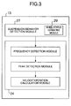
- Fig. 3 shows a flow until the radio wave radar sensor 13 detects the behavior of the suspension.
- the radio wave radar sensor 13 includes an RF module 27 for detecting the behavior of the suspension and a processor 24 for carrying out information processing.
- a processor 24 for carrying out information processing.
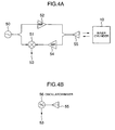
- Figs. 4A and 4B show the composition of the RF module 27 as a suspension behavior detection module.
- a signal from an oscillator 50 is amplified by an amplifier 52 and transmitted by a TX/RX (transmission/reception) antenna 55, and reflected waves from the inner cylinder 10 are received by the TX/RX antenna 55.
- a reception signal obtained by the TX/RX antenna 55 is amplified by a low noise amplifier 54 and mixed with the signal from the oscillator 50 by a mixer 51, by which an IF (Intermediate Frequency) signal 53 is obtained.
- IF Intermediate Frequency
- Fig. 4A shows such an example, in which the amplifier 52 and the low noise amplifier 54 are left out and an oscillator/mixer 56 serving as both an oscillator and a mixer is connected to the TX/RX antenna 55.
- the function of the suspension behavior detection module does not differ between Fig. 4A and Fig. 4B.
- a frequency detection module will be explained below referring to Figs. 5A through 6B.
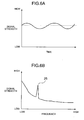
- the suspension does not vibrate and the distance between the radio wave radar sensor 13 and the inner cylinder 10 is almost constant, by which the strength of the IF signal 53 outputted by the RF module 27 of the radio wave radar sensor 13 behaves as shown in Fig. 5A.
- the suspension vibrates and the distance between the radio wave radar sensor 13 and the inner cylinder 10 changes, by which the strength of the IF signal 53 outputted by the RF module 27 of the radio wave radar sensor 13 behaves as shown in Fig. 6A.
- the IF signal 53 is A/D converted (by passing the signal through a high-pass filter) and transformed by the fast Fourier transform, by which the relationship between the frequency and the signal strength is derived as shown in Figs. 5B and 6B (corresponding to Figs. 5A and 6A, respectively).
- the high signal strength at low frequencies is caused by the so-called 1/F noise which is dependent on the frequency band.
- the peak 25 seen in Fig. 6B indicates the relative behavior between the radio wave radar sensor 13 and the inner cylinder 10, that is, the behavior of the suspension.
- a peak detection module for detecting the peak 25 shown in Fig. 6B will be explained below referring to Figs. 7 and 8.
- the position of the radio wave radar sensor 13 (the position of the piston 12) can also be obtained by integrating the velocity V1.
- the velocity C1 of the radio wave is determined by the dielectric constant of the medium and barely varies depending on the flow, temperature and pressure of the medium.
- the variation in the radio wave velocity C1 is small and the error included in the relative velocity V1 between the super-spring structure and the sub-spring structure obtained from the expression (2) is also small. Therefore, the radio wave radar is more advantageous compared to ultrasonic radars.
- the position of the radio wave radar sensor 13 position of the piston 12
- the velocity of the radio wave radar sensor 13 can also be obtained by differentiating the position.
- the error included in the relative velocity between the super-spring structure and the sub-spring structure is small thanks to the small variation in the radio wave velocity, which is an advantage over ultrasonic radars.
- the reflection coefficient for the radio waves transmitted by the radio wave radar sensor 13 is stabilized and thereby the detection of the suspension behavior can be carried out more stably compared to an ordinary inner cylinder with a plane surface, irrespective of the suspension behavior and installation conditions of the radio wave radar.
- the trigonal pyramid-like shape is used here, similar effect can also be achieved by other types of pyramid, cones, spherical surfaces, etc.
- radio wave radar sensor 13 is attached to the rod 7 in the above embodiment, similar effects can also be attained by attaching the radio wave radar sensor 13 to the inner cylinder 10 to detect the behavior of the rod 7.
- An MMIC (Microwave Monolithic Integrated Circuit) 105 (forming the RF module 27 of the radio wave radar sensor 13 shown in Fig. 4A or 4B) and the processor 24 are mounted in a ceramic package 102, with an antenna of the MMIC 105 placed substantially at the center of the package 102.
- a ceramic cover 107 provided with a dielectric lens 106 is joined to the package 102 by a brazing material, etc. so that the axis of the dielectric lens 106 will be coaxial with the radio wave transmission axis of the antenna.
- the MMIC 105 and the processor 24 are connected together by wire bonding by Au wires 104.
- a power line to the MMIC 105 and a signal line from the processor 24 are kept continuous and conductive via pins penetrating the package 102 and cables 100 placed in a hollow part 101 of the rod 7.
- the cables 100 are connected to a connector 4 shown in Fig. 2.
- the MMIC forming a distribution constant circuit, gets smaller as the frequency gets higher in an inversely proportional relationship. Therefore, the cost of the MMIC can be reduced excellently by employing an extremely high frequency in a millimeter wave band.
- the package 102 is attached to a housing 109 by swaging a part of the housing toward the package via an O ring 108.
- the housing 109 has a threaded part 111, by which the housing 109 is screwed and fastened to the rod 7 via packing 110.
- the MMIC 105 and the processor 24 can be hermetically sealed in a highly pressure-resistant structure even in the suspension oil.
- the rod 7 is generally provided with a screw thread which is used for fixing the piston 12 thereon, and the radio wave radar sensor 13 is attached to the rod 7 by use of the screw thread, by which very easy attachment of the radio wave radar sensor 13 is realized. Further, since the antenna is placed substantially at the center, the radio wave transmission/reception conditions are not affected by the screwing status of the radio wave radar sensor 13, which allows high productivity of the suspension device.
- connection of the housing 109 to the rod 7 is not restricted to the screwing described above; welding the housing 109 to the rod 7 is also an excellent method since the welding can also secure the hermeticity, highly pressure resistance, satisfactory attachment to the rod 7, and insusceptibility of the radio wave transmission/reception conditions to welding status.
- the suspension device may also be provided with a position sensor 23 for detecting positional relationship between the super-spring structure and the sub-spring structure in the rod axis direction regarding at least one point.
- the position of the piston 12 calculated by the processor 24 of the radio wave radar sensor 13 is corrected based on the positional information obtained by the position sensor 23, by which precise measurement of the position and self-diagnosis of the radio wave radar sensor 13 can be realized excellently.
- a wheel status estimating module 29 which estimates air pressure status and attachment status of the wheel based on the relative behavior information on the rod 7 and the inner cylinder 10.
- a burst, faulty attachment, poor balance, etc. of the wheel can be detected by the suspension device and that is highly advantageous.
- the relative behavior information on the rod 7 and the inner cylinder 10 can also be obtained by use of an acceleration sensor attached to the sub-spring structure for detecting acceleration, a linear sensor for obtaining positional information on the rod 7 and the inner cylinder 10, an ultrasonic radar sensor, an optical radar sensor, etc., instead of using the radio wave radar sensor.
- the behavior of the suspension device can be detected correctly and the result of the detection can be applied to suspension control, by which contributions of the suspension devices to the improvement of riding comfort and safety control of vehicles such as cars can be increased considerably.
Landscapes
- Engineering & Computer Science (AREA)
- Radar, Positioning & Navigation (AREA)
- Remote Sensing (AREA)
- Physics & Mathematics (AREA)
- Computer Networks & Wireless Communication (AREA)
- General Physics & Mathematics (AREA)
- General Engineering & Computer Science (AREA)
- Mechanical Engineering (AREA)
- Electromagnetism (AREA)
- Vehicle Body Suspensions (AREA)
- Measuring Fluid Pressure (AREA)
- Fluid-Damping Devices (AREA)
- Radar Systems Or Details Thereof (AREA)
Applications Claiming Priority (2)
| Application Number | Priority Date | Filing Date | Title |
|---|---|---|---|
| JP2003348950 | 2003-10-08 | ||
| JP2003348950A JP2005112155A (ja) | 2003-10-08 | 2003-10-08 | サスペンション装置 |
Publications (2)
| Publication Number | Publication Date |
|---|---|
| EP1522431A2 true EP1522431A2 (fr) | 2005-04-13 |
| EP1522431A3 EP1522431A3 (fr) | 2005-10-05 |
Family
ID=34309225
Family Applications (1)
| Application Number | Title | Priority Date | Filing Date |
|---|---|---|---|
| EP04024039A Withdrawn EP1522431A3 (fr) | 2003-10-08 | 2004-10-08 | Dispositif de suspension de véhicule |
Country Status (3)
| Country | Link |
|---|---|
| US (1) | US20050110226A1 (fr) |
| EP (1) | EP1522431A3 (fr) |
| JP (1) | JP2005112155A (fr) |
Cited By (9)
| Publication number | Priority date | Publication date | Assignee | Title |
|---|---|---|---|---|
| DE102005008403A1 (de) * | 2005-02-24 | 2006-09-14 | Knorr-Bremse Systeme für Nutzfahrzeuge GmbH | Sensoreinrichtung zur Messung des Einfederwegs und/oder der Einfedergeschwindigkeit von Rädern und/oder Achsen von Fahrzeugen |
| WO2007137647A1 (fr) * | 2006-05-31 | 2007-12-06 | Contitech Luftfedersysteme Gmbh | Détermination de la hauteur d'un amortisseur pneumatique selon un procédé de mesure du temps de parcours d'une impulsion |
| WO2008054516A3 (fr) * | 2006-05-08 | 2008-08-14 | Bfs Diversified Products Llc | Système et procédé de détermination de distance |
| US7490817B2 (en) | 2005-01-04 | 2009-02-17 | Bfs Diversified Products Llc | Distance indicating system and method |
| US7532110B2 (en) | 2006-01-23 | 2009-05-12 | Bfs Diversified Products, Llc | Air spring distance indicating system and method |
| EP2208624A2 (fr) | 2009-01-20 | 2010-07-21 | Haldex Brake Products GmbH | Installation de ressort pneumatique doté d'une limitation en hauteur |
| US7959136B2 (en) | 2005-04-27 | 2011-06-14 | Bfs Diversified Products, Llc | Sensing and communication system and method |
| ES2379847A1 (es) * | 2008-10-10 | 2012-05-04 | Robert Bosch Gmbh | Amortiguador para un vehiculo y sistema de funcionamiento para un amortiguador de vehiculos. |
| EP3999873A1 (fr) * | 2019-07-15 | 2022-05-25 | Firestone Industrial Products Company, LLC | Capteurs de ressort à gaz utilisant des ensembles radar à ondes millimétriques et ressort à gaz et systèmes de suspension les comprenant |
Families Citing this family (7)
| Publication number | Priority date | Publication date | Assignee | Title |
|---|---|---|---|---|
| US7665585B2 (en) * | 2004-09-03 | 2010-02-23 | Alexandridis Alexander A | Vehicle suspension system and method for operating |
| EP2137009A1 (fr) * | 2007-03-16 | 2009-12-30 | Nira Dynamics AB | Utilisation d'une information de suspension dans la détection d'un écart de pression d'un pneu de véhicule |
| DE102009032897B4 (de) * | 2009-07-10 | 2013-09-19 | Stabilus Gmbh | Kolben-Zylinderaggregat |
| US20120034109A1 (en) * | 2010-08-09 | 2012-02-09 | Aidan Marcus Tout | System and method for measuring pressure applied by a piezo-electric pump |
| JP2016161048A (ja) * | 2015-03-02 | 2016-09-05 | Kyb株式会社 | 緩衝器 |
| US10262473B2 (en) | 2015-07-30 | 2019-04-16 | Ford Global Technologies, Llc | Systems and methods for suspension vibration on-board detection |
| WO2021011595A1 (fr) * | 2019-07-15 | 2021-01-21 | Firestone Industrial Products Company, Llc | Ensemble pneu de véhicule comprenant une hauteur de gonflage interne et capteur d'aire de contact utilisant un radar à longueur d'onde millimétrique |
Citations (2)
| Publication number | Priority date | Publication date | Assignee | Title |
|---|---|---|---|---|
| JPH0710642B2 (ja) | 1990-03-15 | 1995-02-08 | モンロー・オート・イクイプメント・カンパニー | ドップラー流体速度センサを備えるショック・アブソーバ |
| JPH1172132A (ja) | 1997-06-25 | 1999-03-16 | Japan Radio Co Ltd | ばね上、ばね下構造体の相対挙動測定装置 |
Family Cites Families (19)
| Publication number | Priority date | Publication date | Assignee | Title |
|---|---|---|---|---|
| US4574267A (en) * | 1982-05-06 | 1986-03-04 | Trw Inc. | Tire pressure warning system |
| DE3423602A1 (de) * | 1984-06-27 | 1986-01-09 | Robert Bosch Gmbh, 7000 Stuttgart | Messvorrichtung fuer den abstand zwischen der karosserie und der achse eines fahrzeugs |
| GB2172995A (en) * | 1985-03-30 | 1986-10-01 | Emhart Ind | Monitoring the position of a member |
| GB8516765D0 (en) * | 1985-07-02 | 1985-08-07 | Dunlop Ltd | Suspension systems |
| US4995635A (en) * | 1990-03-21 | 1991-02-26 | Monroe Auto Equipment Company | Ultrasonic Doppler velocity sensing within a hydraulic actuator |
| DE4014876A1 (de) * | 1990-05-09 | 1991-11-14 | Bayerische Motoren Werke Ag | Verfahren und einrichtung zum ermitteln und/oder ueberwachen des zustands einer technischen komponente eines kraftfahrzeugs |
| US5104144A (en) * | 1990-09-25 | 1992-04-14 | Monroe Auto Equipment Company | Shock absorber with sonar position sensor |
| US5497324A (en) * | 1991-05-20 | 1996-03-05 | General Motors Corporation | Vehicle suspension system with gain scheduling |
| US5150060A (en) * | 1991-07-05 | 1992-09-22 | Caterpillar Inc. | Multiplexed radio frequency linear position sensor system |
| KR970011089B1 (ko) * | 1992-02-14 | 1997-07-07 | 미쯔비시 지도샤 고교 가부시끼가이샤 | 노면상태의 식별방법 및 써스펜션의 제어 장치 |
| DE4345242A1 (de) * | 1993-09-15 | 1995-04-06 | Endress Hauser Gmbh Co | Frequenzumsetzungsschaltung für ein Radar-Abstandsmeßgerät |
| DE19648112C1 (de) * | 1996-11-21 | 1998-03-05 | Contitech Luftfedersyst Gmbh | Einrichtung zur berührungslosen Abstandsmessung |
| DE19700966C1 (de) * | 1997-01-14 | 1998-04-23 | Contitech Luftfedersyst Gmbh | Einrichtung zur berührungslosen Abstands- und Druckmessung innerhalb einer Luftfeder |
| DE19701530C1 (de) * | 1997-01-17 | 1998-08-06 | Contitech Luftfedersyst Gmbh | Einrichtung zur Bestimmung des axialen Abstandes zweier Endglieder einer Gasdruckfeder |
| DE19801054C1 (de) * | 1998-01-14 | 1999-07-29 | Mannesmann Sachs Ag | Kolben-Zylinderaggregat mit einer Bewegungserfassungseinrichtung |
| DE19820877C2 (de) * | 1998-05-09 | 2002-09-19 | Contitech Luftfedersyst Gmbh | Berührungslose Abstands- und Druckmessung innerhalb einer Luftfeder |
| DE10051825A1 (de) * | 2000-10-19 | 2002-04-25 | Contitech Luftfedersyst Gmbh | Kraftfahrzeug-Luftfedersystem mit Ultraschall-Messanordnung |
| DE10147185A1 (de) * | 2001-09-25 | 2003-04-24 | Knorr Bremse Systeme | Bestimmung von Federhöhe und Druck in Federelementen, insbesondere Luftfedern, für Kraftfahrzeuge |
| DE10151593A1 (de) * | 2001-10-18 | 2003-04-30 | Contitech Luftfedersyst Gmbh | Abstands- und Druckmessung innerhalb einer Luftfeder |
-
2003
- 2003-10-08 JP JP2003348950A patent/JP2005112155A/ja active Pending
-
2004
- 2004-10-07 US US10/959,320 patent/US20050110226A1/en not_active Abandoned
- 2004-10-08 EP EP04024039A patent/EP1522431A3/fr not_active Withdrawn
Patent Citations (2)
| Publication number | Priority date | Publication date | Assignee | Title |
|---|---|---|---|---|
| JPH0710642B2 (ja) | 1990-03-15 | 1995-02-08 | モンロー・オート・イクイプメント・カンパニー | ドップラー流体速度センサを備えるショック・アブソーバ |
| JPH1172132A (ja) | 1997-06-25 | 1999-03-16 | Japan Radio Co Ltd | ばね上、ばね下構造体の相対挙動測定装置 |
Cited By (17)
| Publication number | Priority date | Publication date | Assignee | Title |
|---|---|---|---|---|
| US7490817B2 (en) | 2005-01-04 | 2009-02-17 | Bfs Diversified Products Llc | Distance indicating system and method |
| US7959137B2 (en) | 2005-01-04 | 2011-06-14 | Bfs Diversified Products, Llc | Distance indicating system and method |
| US8692706B2 (en) | 2005-02-24 | 2014-04-08 | Knorr-Bremse Systeme Fuer Nutzfahrzeuge Gmbh | Sensor device for measuring the compression travel and/or the compression rate of wheels and/or axles of vehicles |
| DE102005008403B4 (de) * | 2005-02-24 | 2008-08-21 | Knorr-Bremse Systeme für Nutzfahrzeuge GmbH | Sensoreinrichtung zur Messung des Einfederwegs und/oder der Einfedergeschwindigkeit von Achsen von Fahrzeugen |
| DE102005008403A1 (de) * | 2005-02-24 | 2006-09-14 | Knorr-Bremse Systeme für Nutzfahrzeuge GmbH | Sensoreinrichtung zur Messung des Einfederwegs und/oder der Einfedergeschwindigkeit von Rädern und/oder Achsen von Fahrzeugen |
| US7959136B2 (en) | 2005-04-27 | 2011-06-14 | Bfs Diversified Products, Llc | Sensing and communication system and method |
| US7532110B2 (en) | 2006-01-23 | 2009-05-12 | Bfs Diversified Products, Llc | Air spring distance indicating system and method |
| WO2008054516A3 (fr) * | 2006-05-08 | 2008-08-14 | Bfs Diversified Products Llc | Système et procédé de détermination de distance |
| US7733239B2 (en) | 2006-05-08 | 2010-06-08 | Bfs Diversified Products, Llc | Distance determining system and method |
| WO2007137647A1 (fr) * | 2006-05-31 | 2007-12-06 | Contitech Luftfedersysteme Gmbh | Détermination de la hauteur d'un amortisseur pneumatique selon un procédé de mesure du temps de parcours d'une impulsion |
| DE102006025326B4 (de) * | 2006-05-31 | 2017-05-04 | Contitech Luftfedersysteme Gmbh | Bestimmung der Federhöhe einer Luftfeder nach einem Impuls-Laufzeitmessverfahren |
| ES2379847A1 (es) * | 2008-10-10 | 2012-05-04 | Robert Bosch Gmbh | Amortiguador para un vehiculo y sistema de funcionamiento para un amortiguador de vehiculos. |
| DE102009005229A1 (de) | 2009-01-20 | 2010-07-29 | Haldex Brake Products Gmbh | Luftfederanlage mit Höhenbegrenzung |
| DE102009005229B4 (de) * | 2009-01-20 | 2012-11-15 | Haldex Brake Products Gmbh | Luftfederanlage mit Höhenbegrenzung |
| EP2208624A2 (fr) | 2009-01-20 | 2010-07-21 | Haldex Brake Products GmbH | Installation de ressort pneumatique doté d'une limitation en hauteur |
| DE102009005229C5 (de) | 2009-01-20 | 2019-09-12 | Haldex Brake Products Aktiebolag | Luftfederanlage mit Höhenbegrenzung |
| EP3999873A1 (fr) * | 2019-07-15 | 2022-05-25 | Firestone Industrial Products Company, LLC | Capteurs de ressort à gaz utilisant des ensembles radar à ondes millimétriques et ressort à gaz et systèmes de suspension les comprenant |
Also Published As
| Publication number | Publication date |
|---|---|
| EP1522431A3 (fr) | 2005-10-05 |
| JP2005112155A (ja) | 2005-04-28 |
| US20050110226A1 (en) | 2005-05-26 |
Similar Documents
| Publication | Publication Date | Title |
|---|---|---|
| US20050110226A1 (en) | Suspension device for vehicle | |
| KR100742711B1 (ko) | 초음파 송수파기 | |
| US5936161A (en) | Arrangement for making contactless distance measurements | |
| US6073491A (en) | Method and arrangement for making contactless distance and pressure measurements within an air spring | |
| US7373840B2 (en) | Ultrasonic flowmeter having a transmitting body fixed on the outer peripheral surface of the pipe | |
| US4437032A (en) | Sensor for distance measurement by ultrasound | |
| JP4367533B2 (ja) | 超音波センサの自己診断方法 | |
| US8174377B2 (en) | Suspension height sensor | |
| JP4456998B2 (ja) | 速度センサおよびそれを用いた対地車速センサ | |
| US8692706B2 (en) | Sensor device for measuring the compression travel and/or the compression rate of wheels and/or axles of vehicles | |
| US5104144A (en) | Shock absorber with sonar position sensor | |
| EP2277015B1 (fr) | Appareil non intrusif incorporant un boîtier de détecteurs protecteur permettant de mesurer l'écoulement d'un fluide | |
| US6637269B2 (en) | Motor vehicle air spring system having an ultrasonic measurement arrangement | |
| US6318524B1 (en) | Piston cylinder unit with a movement determination device | |
| US20120167689A1 (en) | Ultrasonic sensor | |
| CN114207312B (zh) | 气弹簧组件、悬架系统以及位移和速度传感器 | |
| WO2011090484A1 (fr) | Transducteur ultrasonique camouflé | |
| US20110259107A1 (en) | ultrasonic sensor | |
| JPH04503792A (ja) | ドップラー流体速度センサを備えるショック・アブソーバ | |
| JP3464786B2 (ja) | 間隔測定装置 | |
| CN114174082A (zh) | 使用毫米波长雷达的包括内部充气高度和接地印迹传感器的车辆轮胎组件 | |
| JP2000032594A (ja) | 超音波送受波器 | |
| JP6691002B2 (ja) | 超音波送受波器 | |
| JPH1172132A (ja) | ばね上、ばね下構造体の相対挙動測定装置 | |
| JP2001246918A (ja) | 車両用エアサスペンションの荷重測定装置および圧力測定装置 |
Legal Events
| Date | Code | Title | Description |
|---|---|---|---|
| PUAI | Public reference made under article 153(3) epc to a published international application that has entered the european phase |
Free format text: ORIGINAL CODE: 0009012 |
|
| AK | Designated contracting states |
Kind code of ref document: A2 Designated state(s): AT BE BG CH CY CZ DE DK EE ES FI FR GB GR HU IE IT LI LU MC NL PL PT RO SE SI SK TR |
|
| AX | Request for extension of the european patent |
Extension state: AL HR LT LV MK |
|
| PUAL | Search report despatched |
Free format text: ORIGINAL CODE: 0009013 |
|
| AK | Designated contracting states |
Kind code of ref document: A3 Designated state(s): AT BE BG CH CY CZ DE DK EE ES FI FR GB GR HU IE IT LI LU MC NL PL PT RO SE SI SK TR |
|
| AX | Request for extension of the european patent |
Extension state: AL HR LT LV MK |
|
| AKX | Designation fees paid |
Designated state(s): DE |
|
| STAA | Information on the status of an ep patent application or granted ep patent |
Free format text: STATUS: THE APPLICATION IS DEEMED TO BE WITHDRAWN |
|
| 18D | Application deemed to be withdrawn |
Effective date: 20060406 |