EP1522433B1 - Stabilizer bar lateral retainer collar - Google Patents
Stabilizer bar lateral retainer collar Download PDFInfo
- Publication number
- EP1522433B1 EP1522433B1 EP04256173A EP04256173A EP1522433B1 EP 1522433 B1 EP1522433 B1 EP 1522433B1 EP 04256173 A EP04256173 A EP 04256173A EP 04256173 A EP04256173 A EP 04256173A EP 1522433 B1 EP1522433 B1 EP 1522433B1
- Authority
- EP
- European Patent Office
- Prior art keywords
- stabilizer bar
- shift collar
- recited
- collar
- outer perimeter
- Prior art date
- Legal status (The legal status is an assumption and is not a legal conclusion. Google has not performed a legal analysis and makes no representation as to the accuracy of the status listed.)
- Expired - Lifetime
Links
- 239000003381 stabilizer Substances 0.000 title claims description 35
- 238000002788 crimping Methods 0.000 claims description 11
- 239000007769 metal material Substances 0.000 claims description 2
- 238000000034 method Methods 0.000 claims 4
- 239000000725 suspension Substances 0.000 description 9
- 230000002035 prolonged effect Effects 0.000 description 2
- 238000005096 rolling process Methods 0.000 description 2
- 238000005452 bending Methods 0.000 description 1
- 230000000717 retained effect Effects 0.000 description 1
- 230000035939 shock Effects 0.000 description 1
- 238000005480 shot peening Methods 0.000 description 1
Images
Classifications
-
- B—PERFORMING OPERATIONS; TRANSPORTING
- B60—VEHICLES IN GENERAL
- B60G—VEHICLE SUSPENSION ARRANGEMENTS
- B60G21/00—Interconnection systems for two or more resiliently-suspended wheels, e.g. for stabilising a vehicle body with respect to acceleration, deceleration or centrifugal forces
- B60G21/02—Interconnection systems for two or more resiliently-suspended wheels, e.g. for stabilising a vehicle body with respect to acceleration, deceleration or centrifugal forces permanently interconnected
- B60G21/04—Interconnection systems for two or more resiliently-suspended wheels, e.g. for stabilising a vehicle body with respect to acceleration, deceleration or centrifugal forces permanently interconnected mechanically
- B60G21/05—Interconnection systems for two or more resiliently-suspended wheels, e.g. for stabilising a vehicle body with respect to acceleration, deceleration or centrifugal forces permanently interconnected mechanically between wheels on the same axle but on different sides of the vehicle, i.e. the left and right wheel suspensions being interconnected
- B60G21/055—Stabiliser bars
- B60G21/0551—Mounting means therefor
-
- B—PERFORMING OPERATIONS; TRANSPORTING
- B60—VEHICLES IN GENERAL
- B60G—VEHICLE SUSPENSION ARRANGEMENTS
- B60G2202/00—Indexing codes relating to the type of spring, damper or actuator
- B60G2202/10—Type of spring
- B60G2202/13—Torsion spring
- B60G2202/135—Stabiliser bar and/or tube
-
- B—PERFORMING OPERATIONS; TRANSPORTING
- B60—VEHICLES IN GENERAL
- B60G—VEHICLE SUSPENSION ARRANGEMENTS
- B60G2204/00—Indexing codes related to suspensions per se or to auxiliary parts
- B60G2204/10—Mounting of suspension elements
- B60G2204/12—Mounting of springs or dampers
- B60G2204/122—Mounting of torsion springs
- B60G2204/1222—Middle mounts of stabiliser on vehicle body or chassis
-
- B—PERFORMING OPERATIONS; TRANSPORTING
- B60—VEHICLES IN GENERAL
- B60G—VEHICLE SUSPENSION ARRANGEMENTS
- B60G2204/00—Indexing codes related to suspensions per se or to auxiliary parts
- B60G2204/40—Auxiliary suspension parts; Adjustment of suspensions
- B60G2204/44—Centering or positioning means
-
- B—PERFORMING OPERATIONS; TRANSPORTING
- B60—VEHICLES IN GENERAL
- B60G—VEHICLE SUSPENSION ARRANGEMENTS
- B60G2204/00—Indexing codes related to suspensions per se or to auxiliary parts
- B60G2204/40—Auxiliary suspension parts; Adjustment of suspensions
- B60G2204/45—Stops limiting travel
-
- B—PERFORMING OPERATIONS; TRANSPORTING
- B60—VEHICLES IN GENERAL
- B60G—VEHICLE SUSPENSION ARRANGEMENTS
- B60G2206/00—Indexing codes related to the manufacturing of suspensions: constructional features, the materials used, procedures or tools
- B60G2206/01—Constructional features of suspension elements, e.g. arms, dampers, springs
- B60G2206/80—Manufacturing procedures
- B60G2206/82—Joining
- B60G2206/8209—Joining by deformation
-
- B—PERFORMING OPERATIONS; TRANSPORTING
- B60—VEHICLES IN GENERAL
- B60G—VEHICLE SUSPENSION ARRANGEMENTS
- B60G2206/00—Indexing codes related to the manufacturing of suspensions: constructional features, the materials used, procedures or tools
- B60G2206/01—Constructional features of suspension elements, e.g. arms, dampers, springs
- B60G2206/90—Maintenance
- B60G2206/91—Assembly procedures
Definitions
- the present invention relates to a vehicle stabilizer bar, and more particularly to a lateral retainer collar therefor.
- Such stabilizer bar assembly according to the preamble of claim 1 is known from JP 2001 165 127 A .
- Vehicles are commonly equipped with independent suspension systems for absorbing road shock and other vibrations while providing a smooth and comfortable ride for the vehicle occupants.
- suspension systems of this type a stabilizer bar is often used to increase the roll rigidity and improve the steering stability of the vehicle.
- the stabilizer bar is a rod-shaped member oriented to extend laterally across the vehicle and an arm segment extending longitudinally at each end of the central segment.
- the central segment of the stabilizer bar is supported for rotation about its own longitudinal axis by one or more mounting brackets which are fixed to the vehicle body or frame.
- the distal end of each arm segment is coupled to a control arm of the suspension system by an end link.
- the arm segments pivot in opposite directions with respect to the longitudinal axis of the central segment.
- torsional reaction forces are generated which act through the arm segments to urge the control arms to move toward their normal position.
- the vehicle body will be prevented from excessive rolling or leaning to either side by the torsional resistance produced by the stabilizer bar.
- the stabilizer bar may shift laterally during suspension articulation.
- the lateral shift is resisted by a multiple of collars mounted to the central segment of the stabilizer bar.
- the collars facially engage bushings mounting to the vehicle body or frame to minimize lateral shift of the stabilizer bar.
- the collars are mounted to the stabilizer bar after final shot peening and bending operations are performed to avoid reducing the stabilizer bar integrity. Due to the collar mounting locations and forming requirements, conventional collars are overmolded plastic components. Although effective, overmolded collars may be subject to relatively rapid wear while metallic collars have heretofore been complicated to mount.
- the anti-shift collar according to the present invention prevents lateral movement of a stabilizer bar assembly.
- the anti-shift collar has an internal profile that allows it to be mounted onto the bar over previously formed end. This end is typically a forged spade end and the internal profit of the collar reflects this form.
- the anti-shift collar is crimped to the central segment of the stabilizer bar and is locked to the central segment thereby.
- the present invention therefore provide an inexpensive collar which is uncomplicated to mount yet resists side forces from the stabilizer bar for a prolonged service life without appreciable wear.
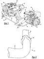
- Figure 1 illustrates a general perspective view of an independent front wheel suspension system 10. It should be understood that although a particular suspension is disclosed in the illustrated embodiment, any suspension which utilizes a stabilizer bar will also benefit from the present invention.
- a vehicle frame 12 includes a pair of longitudinal frame rails 14 and a crossbeam 16.
- Suspension system 10 includes a long lower control arm 18 and a short upper control arm 20 which are both pivotally attached to frame 12.
- a strut assembly having a helical coil spring 22 and a strut damper 24 is retained between an intermediate portion of lower control arm 18 and frame 12 to support the weight of the vehicle body and any loads which are transmitted through lower control arm 18.
- Upper control arm 20 is connected to lower control arm 18 by a steering knuckle 26.
- a hub and rotor assembly 28 is rotatably attached to a spindle portion 27 of steering knuckle 26 such that a wheel and tire (not shown) may be mounted thereon.
- a stabilizer bar assembly 30 includes an elongated central segment 32 which extends laterally across the vehicle and a pair of arm segments 34 which extend longitudinally along the vehicle at each end of central segment 32.
- Central segment 32 is rotatably attached to frame rails 14 through a pair of mounting brackets 36.
- An anti-shift collar 38 is crimped to the central segment 32 (also illustrated in Figure 2 ) adjacent the mounting brackets 36 to minimize lateral shift of the stabilizer bar 30.
- the anti-shift collar 38 is manufactured of a metallic material such as SAE BS970EN3.
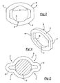
- the anti-shift collar 38 is illustrated prior to crimping. It should be understood that the anti-shift collar 38 may be crimped at any desired location.
- the anti-shift collar 38 includes a generally elliptical outer perimeter 40.
- the smaller radius ends 46 adjacent the clipped ends 47 of the elliptical outer perimeter 40 are preferably clipped. That is, the clipped ends 47 are linear and break the elliptical outer perimeter 40.
- An inner perimeter 42 includes a circular portion 44 and a polygonal portion 48 adjacent each of the clipped ends 47 of the elliptical outer perimeter 40 (also illustrated in Figure 4 ).
- the circular portion 44 is preferably large enough to be received over a finished and shot peened arm segment 34, the elongated central segment 32 and the bends therebetween ( Figure 1 ).
- any formed ends such as forged eyes must also be passed therethrough. That is, the polygonal portions 48 allow the anti-shift collar 38 to be slid to a desired position over the formed ends then crimped into place.
- the anti-shift collar 38 is illustrated after a crimping operation is performed such that the anti-shift collar 38 is locked to the central segment 32 thereby.
- a crimp (illustrated schematically by arrow C) is preferably made upon the elliptical outer perimeter 40 adjacent each polygonal portion 46. That is, the clipped ends 47 are crimped to form pinched areas 50 to lock the anti-shift collar 38 to the central segment 32 of the stabilizer bar assembly 30.
- the configuration of the elliptical outer perimeter 40 and the clipped ends 47 advantageously simplifies crimping to two opposed locations.
- the pinched areas 50 take-up the clearance between the circular portion 44 prior to crimping and the central segment 32. A rigid and relatively uncomplicated mounted is thereby provided.
Landscapes
- Engineering & Computer Science (AREA)
- Mechanical Engineering (AREA)
- Vehicle Body Suspensions (AREA)
Applications Claiming Priority (2)
| Application Number | Priority Date | Filing Date | Title |
|---|---|---|---|
| US10/680,986 US7621513B2 (en) | 2003-10-08 | 2003-10-08 | Stabilizer bar lateral retainer collar |
| US680986 | 2003-10-08 |
Publications (2)
| Publication Number | Publication Date |
|---|---|
| EP1522433A1 EP1522433A1 (en) | 2005-04-13 |
| EP1522433B1 true EP1522433B1 (en) | 2008-02-13 |
Family
ID=34314115
Family Applications (1)
| Application Number | Title | Priority Date | Filing Date |
|---|---|---|---|
| EP04256173A Expired - Lifetime EP1522433B1 (en) | 2003-10-08 | 2004-10-06 | Stabilizer bar lateral retainer collar |
Country Status (4)
| Country | Link |
|---|---|
| US (1) | US7621513B2 (pt) |
| EP (1) | EP1522433B1 (pt) |
| BR (1) | BRPI0404197A (pt) |
| DE (1) | DE602004011719T2 (pt) |
Families Citing this family (8)
| Publication number | Priority date | Publication date | Assignee | Title |
|---|---|---|---|---|
| US7065875B2 (en) * | 2003-11-25 | 2006-06-27 | Automotive Components Holdings, Llc | Bushing support ring for stabilizer bar |
| DE102004031282A1 (de) * | 2004-06-29 | 2006-01-26 | Thyssenkrupp Automotive Ag | Verfahren zum Befestigen von Fixierringen auf Stabilisatoren für Kraftfahrzeuge |
| US7290322B2 (en) * | 2004-09-01 | 2007-11-06 | Automotive Components Holdings, Llc | Method of crimping a ring shaped stop within an annular groove of a stabilizer bar |
| US20080111335A1 (en) * | 2006-11-13 | 2008-05-15 | Thyssenkrupp Bilstein Of America | Stabilizer bar with a lateral retention collar and method of manufacture |
| JP4663752B2 (ja) * | 2008-04-14 | 2011-04-06 | 日本発條株式会社 | スタビライザ装置およびその製造方法 |
| DE102011112387A1 (de) * | 2011-09-03 | 2013-03-07 | Gm Global Technology Operations, Llc | Querstabilisator für ein Kraftfahrzeug |
| JP5988488B2 (ja) * | 2012-10-26 | 2016-09-07 | 日本発條株式会社 | スタビライザ用ブシュ、接着用治具、および、接着方法 |
| US20250296397A1 (en) * | 2024-03-22 | 2025-09-25 | Polaris Industries Inc. | Lateral retention feature for vehicle stabilizer bar |
Family Cites Families (27)
| Publication number | Priority date | Publication date | Assignee | Title |
|---|---|---|---|---|
| US2915321A (en) * | 1953-07-02 | 1959-12-01 | Daimler Benz Ag | Torsion rod spring system for vehicles especially motor vehicles |
| DE972181C (de) * | 1953-07-02 | 1959-06-04 | Daimler Benz Ag | Drehstabfederung fuer Fahrzeuge, insbesondere Kraftfahrzeuge |
| US4082243A (en) * | 1976-11-18 | 1978-04-04 | Keeler Corporation | Collar attachment for support hook |
| US4143887A (en) * | 1977-12-21 | 1979-03-13 | General Motors Corporation | Independent rear suspension system |
| US4192529A (en) * | 1978-01-30 | 1980-03-11 | Toyota Jidosha Kogyo Kabushiki Kaisha | Stabilizer mounting means |
| DE3625148C1 (de) * | 1986-07-25 | 1987-04-16 | Ford Werke Ag | Verfahren zum axialen Festlegen eines Bauteiles auf einer Welle bzw. in einer Bohrung |
| FR2642487B1 (fr) * | 1989-01-31 | 1991-05-10 | Hutchinson | Palier de barre de torsion |
| DE3921457A1 (de) | 1989-06-30 | 1991-01-10 | Hoesch Ag | Torsionsstab |
| US5145273A (en) | 1991-02-22 | 1992-09-08 | Mac Lean Fogg Company | Locking member and stabilizer bar/locking member combination |
| US5108055A (en) * | 1991-09-04 | 1992-04-28 | Amp Incorporated | Conduit holder |
| DE4312958A1 (de) * | 1993-04-21 | 1994-10-27 | Lemfoerder Metallwaren Ag | Kunststofflager für Stabilisatoren in Kraftfahrzeugen |
| DE19543690C2 (de) | 1995-11-23 | 2001-04-19 | Trw Fahrwerksyst Gmbh & Co | Verbindung eines Stabilisators mit der Radaufhängung eines Kraftfahrzeuges |
| KR100245685B1 (ko) * | 1995-12-15 | 2000-04-01 | 정몽규 | 자동차의 스테이빌라이저 바아 고정구조 |
| DE69719493T2 (de) | 1996-03-29 | 2003-12-24 | Waukesha Tool & Stamping, Inc. | Ringförmiger flansch für wellen |
| FR2755603B1 (fr) * | 1996-11-12 | 1999-02-26 | Jacques Preaut | Ensemble d'ancillaires pour la pose de cotyles de protheses de hanche, et ensemble prothetique de cotyle pret a etre pose |
| JP3909531B2 (ja) | 1997-01-08 | 2007-04-25 | 中央発條株式会社 | 自動車用スタビライザ |
| US5836598A (en) * | 1997-02-11 | 1998-11-17 | Illinois Tool Works Inc. | Apparatus for vehicle suspension stabilization system and method thereof |
| EP1071571B1 (en) * | 1998-04-23 | 2004-10-20 | Nhk Spring Co.Ltd. | Retaining arrangement for a rod member |
| JP3963592B2 (ja) | 1998-09-21 | 2007-08-22 | 横浜機工株式会社 | 棒材のずれ防止構造 |
| US6206392B1 (en) * | 1998-05-26 | 2001-03-27 | Visteon Global Technologies, Inc. | Stabilizer bar apparatus for use in a vehicle suspension |
| JP2000079819A (ja) | 1998-07-01 | 2000-03-21 | Mitsubishi Steel Mfg Co Ltd | スタビライザの横ずれ防止装置 |
| US6254114B1 (en) * | 1998-11-09 | 2001-07-03 | American Axle & Manufacturing, Inc. | Composite stabilizer bar link |
| JP4474560B2 (ja) | 2000-02-18 | 2010-06-09 | 中央発條株式会社 | 自動車用スタビライザ |
| US20020074761A1 (en) * | 2000-12-14 | 2002-06-20 | Kincaid Jeffrey Lee | Robust, low mass stabilizer bar link assembly |
| US20030111817A1 (en) * | 2001-12-19 | 2003-06-19 | Joseph Fader | Band for anti-lateral movement of stabilizer bar |
| DE10321716A1 (de) * | 2003-05-14 | 2004-12-09 | Volkswagen Ag | Verfahren zur Befestigung eines metallischen Fixierrings an einem Torsionsstabilisator und Anordnung bestehend aus einem Torsionsstabilisator und einem metallischen Fixierring |
| DE102004031282A1 (de) * | 2004-06-29 | 2006-01-26 | Thyssenkrupp Automotive Ag | Verfahren zum Befestigen von Fixierringen auf Stabilisatoren für Kraftfahrzeuge |
-
2003
- 2003-10-08 US US10/680,986 patent/US7621513B2/en not_active Expired - Fee Related
-
2004
- 2004-09-30 BR BR0404197-6A patent/BRPI0404197A/pt not_active Application Discontinuation
- 2004-10-06 DE DE602004011719T patent/DE602004011719T2/de not_active Expired - Fee Related
- 2004-10-06 EP EP04256173A patent/EP1522433B1/en not_active Expired - Lifetime
Also Published As
| Publication number | Publication date |
|---|---|
| DE602004011719T2 (de) | 2009-02-19 |
| BRPI0404197A (pt) | 2005-06-28 |
| US20050077663A1 (en) | 2005-04-14 |
| DE602004011719D1 (de) | 2008-03-27 |
| US7621513B2 (en) | 2009-11-24 |
| EP1522433A1 (en) | 2005-04-13 |
Similar Documents
| Publication | Publication Date | Title |
|---|---|---|
| US8356826B2 (en) | Suspension system for a vehicle | |
| US5895063A (en) | Wheel suspension system | |
| US5954353A (en) | Plug in direct acting stabilizer bar link | |
| US20090058031A1 (en) | Stabilizer bar assembly for vehicle suspension system | |
| EP1051304B1 (en) | Suspension link assembly | |
| EP1071571B1 (en) | Retaining arrangement for a rod member | |
| EP0770506B1 (en) | Improvements in and relating to anti-roll bar assemblies for road vehicles | |
| JP4015235B2 (ja) | 自動車用スタビライザ装置 | |
| JP5324101B2 (ja) | 台形断面のクロスメンバーを備えるフレキシブル車軸、該クロスメンバー、車両、および製造方法 | |
| US9102210B2 (en) | Suspension system for a vehicle and method | |
| EP1522433A1 (en) | Stabilizer bar lateral retainer collar | |
| JP7517768B2 (ja) | スタビライザ装置 | |
| US6648350B1 (en) | Suspension system for a vehicle having a vehicle stabilizer bar with integral end links | |
| EP2311670B1 (en) | Suspension system | |
| EP1555145A1 (en) | Spray formed stablizer bar lateral retainer | |
| EP1065077A1 (en) | Plug in direct acting stabilizer bar link | |
| JP2005226673A (ja) | コイルばね及び懸架装置 | |
| JPH11115430A (ja) | サスペンションアーム | |
| JP3891095B2 (ja) | サスペンションブッシュ | |
| US12337646B2 (en) | Vehicle suspension systems and methods | |
| JP2010047041A (ja) | サスペンション用ブッシュ | |
| JPH0636905U (ja) | トレーリングアーム式車両懸架装置 | |
| JPH06270642A (ja) | 自動車用スタビライザ | |
| KR19990038299A (ko) | 차량의 후륜 현가장치 | |
| MXPA06001924A (en) | Split outer tube anti-walkout bushing |
Legal Events
| Date | Code | Title | Description |
|---|---|---|---|
| PUAI | Public reference made under article 153(3) epc to a published international application that has entered the european phase |
Free format text: ORIGINAL CODE: 0009012 |
|
| AK | Designated contracting states |
Kind code of ref document: A1 Designated state(s): AT BE BG CH CY CZ DE DK EE ES FI FR GB GR HU IE IT LI LU MC NL PL PT RO SE SI SK TR |
|
| AX | Request for extension of the european patent |
Extension state: AL HR LT LV MK |
|
| 17P | Request for examination filed |
Effective date: 20050411 |
|
| AKX | Designation fees paid |
Designated state(s): DE ES FR GB IT SE |
|
| GRAP | Despatch of communication of intention to grant a patent |
Free format text: ORIGINAL CODE: EPIDOSNIGR1 |
|
| GRAS | Grant fee paid |
Free format text: ORIGINAL CODE: EPIDOSNIGR3 |
|
| RAP1 | Party data changed (applicant data changed or rights of an application transferred) |
Owner name: MERITOR SUSPENSION SYSTEMS COMPANY, U.S. |
|
| GRAA | (expected) grant |
Free format text: ORIGINAL CODE: 0009210 |
|
| AK | Designated contracting states |
Kind code of ref document: B1 Designated state(s): DE ES FR GB IT SE |
|
| REG | Reference to a national code |
Ref country code: GB Ref legal event code: FG4D |
|
| REF | Corresponds to: |
Ref document number: 602004011719 Country of ref document: DE Date of ref document: 20080327 Kind code of ref document: P |
|
| PG25 | Lapsed in a contracting state [announced via postgrant information from national office to epo] |
Ref country code: ES Free format text: LAPSE BECAUSE OF FAILURE TO SUBMIT A TRANSLATION OF THE DESCRIPTION OR TO PAY THE FEE WITHIN THE PRESCRIBED TIME-LIMIT Effective date: 20080524 |
|
| ET | Fr: translation filed | ||
| PG25 | Lapsed in a contracting state [announced via postgrant information from national office to epo] |
Ref country code: SE Free format text: LAPSE BECAUSE OF FAILURE TO SUBMIT A TRANSLATION OF THE DESCRIPTION OR TO PAY THE FEE WITHIN THE PRESCRIBED TIME-LIMIT Effective date: 20080513 |
|
| PLBE | No opposition filed within time limit |
Free format text: ORIGINAL CODE: 0009261 |
|
| STAA | Information on the status of an ep patent application or granted ep patent |
Free format text: STATUS: NO OPPOSITION FILED WITHIN TIME LIMIT |
|
| 26N | No opposition filed |
Effective date: 20081114 |
|
| GBPC | Gb: european patent ceased through non-payment of renewal fee |
Effective date: 20081006 |
|
| REG | Reference to a national code |
Ref country code: FR Ref legal event code: ST Effective date: 20090630 |
|
| PG25 | Lapsed in a contracting state [announced via postgrant information from national office to epo] |
Ref country code: IT Free format text: LAPSE BECAUSE OF FAILURE TO SUBMIT A TRANSLATION OF THE DESCRIPTION OR TO PAY THE FEE WITHIN THE PRESCRIBED TIME-LIMIT Effective date: 20080213 Ref country code: DE Free format text: LAPSE BECAUSE OF NON-PAYMENT OF DUE FEES Effective date: 20090501 |
|
| PG25 | Lapsed in a contracting state [announced via postgrant information from national office to epo] |
Ref country code: FR Free format text: LAPSE BECAUSE OF NON-PAYMENT OF DUE FEES Effective date: 20081031 |
|
| PG25 | Lapsed in a contracting state [announced via postgrant information from national office to epo] |
Ref country code: GB Free format text: LAPSE BECAUSE OF NON-PAYMENT OF DUE FEES Effective date: 20081006 |