EP1522437B1 - Dispositif d'alimentation en air pour climatiser l'habitacle d'un véhicule, en particulier d'un véhicule utilitaire - Google Patents
Dispositif d'alimentation en air pour climatiser l'habitacle d'un véhicule, en particulier d'un véhicule utilitaire Download PDFInfo
- Publication number
- EP1522437B1 EP1522437B1 EP04021650A EP04021650A EP1522437B1 EP 1522437 B1 EP1522437 B1 EP 1522437B1 EP 04021650 A EP04021650 A EP 04021650A EP 04021650 A EP04021650 A EP 04021650A EP 1522437 B1 EP1522437 B1 EP 1522437B1
- Authority
- EP
- European Patent Office
- Prior art keywords
- air
- duct
- region
- vehicle
- supply unit
- Prior art date
- Legal status (The legal status is an assumption and is not a legal conclusion. Google has not performed a legal analysis and makes no representation as to the accuracy of the status listed.)
- Expired - Lifetime
Links
Images


Classifications
-
- B—PERFORMING OPERATIONS; TRANSPORTING
- B60—VEHICLES IN GENERAL
- B60H—ARRANGEMENTS OF HEATING, COOLING, VENTILATING OR OTHER AIR-TREATING DEVICES SPECIALLY ADAPTED FOR PASSENGER OR GOODS SPACES OF VEHICLES
- B60H1/00—Heating, cooling or ventilating devices
- B60H1/00507—Details, e.g. mounting arrangements, desaeration devices
- B60H1/00557—Details of ducts or cables
- B60H1/00564—Details of ducts or cables of air ducts
-
- B—PERFORMING OPERATIONS; TRANSPORTING
- B60—VEHICLES IN GENERAL
- B60H—ARRANGEMENTS OF HEATING, COOLING, VENTILATING OR OTHER AIR-TREATING DEVICES SPECIALLY ADAPTED FOR PASSENGER OR GOODS SPACES OF VEHICLES
- B60H1/00—Heating, cooling or ventilating devices
- B60H1/00357—Air-conditioning arrangements specially adapted for particular vehicles
- B60H1/00378—Air-conditioning arrangements specially adapted for particular vehicles for tractor or load vehicle cabins
-
- B—PERFORMING OPERATIONS; TRANSPORTING
- B60—VEHICLES IN GENERAL
- B60H—ARRANGEMENTS OF HEATING, COOLING, VENTILATING OR OTHER AIR-TREATING DEVICES SPECIALLY ADAPTED FOR PASSENGER OR GOODS SPACES OF VEHICLES
- B60H1/00—Heating, cooling or ventilating devices
- B60H1/24—Ventilating devices where the heating or cooling is irrelevant
- B60H1/241—Ventilating devices where the heating or cooling is irrelevant characterised by the location of ventilation devices in the vehicle
- B60H1/243—Ventilating devices where the heating or cooling is irrelevant characterised by the location of ventilation devices in the vehicle located in the lateral area (e.g. doors, pillars)
-
- B—PERFORMING OPERATIONS; TRANSPORTING
- B60—VEHICLES IN GENERAL
- B60H—ARRANGEMENTS OF HEATING, COOLING, VENTILATING OR OTHER AIR-TREATING DEVICES SPECIALLY ADAPTED FOR PASSENGER OR GOODS SPACES OF VEHICLES
- B60H1/00—Heating, cooling or ventilating devices
- B60H1/24—Ventilating devices where the heating or cooling is irrelevant
- B60H1/241—Ventilating devices where the heating or cooling is irrelevant characterised by the location of ventilation devices in the vehicle
- B60H1/245—Ventilating devices where the heating or cooling is irrelevant characterised by the location of ventilation devices in the vehicle located in the roof
Definitions
- the invention relates to an air supply device for air conditioning a vehicle interior of a vehicle, in particular a utility vehicle, according to the preamble of claim 1.
- an air supply device for air conditioning of a motor vehicle having a headliner which can be arranged in a vehicle interior is already known, on the roof of the roof associated with the vehicle roof at least one air distribution duct which can be coupled to a ventilation source, which extends over at least a partial area of the headliner top and covers it , In the covered headliner top area as a covering area at least one Heilausströmerdüse is provided in the headliner for an air passage into the vehicle interior inside.
- an air supply device in conjunction with a vehicle headliner for a car in which in the headliner extending transversely to the direction of depression recess is incorporated.
- an air distribution channel is used from the headliner top side, which is supplied with air by extending along the rear pillars air channels.
- corresponding outflow openings are used in the region of the air duct.
- An air supply device according to the preamble of claim 1 is also known from DE 100 58 366 A.
- a headliner for a car which comprises a multilayer cladding element with a deformable middle carrier layer made of foamed plastic, arranged on both sides of the carrier layer further also deformable layers and with a vehicle interior facing decorative layer.
- a multilayer chamber element is arranged with a deformable middle carrier layer of foamed plastic arranged on both sides of the carrier layer further also deformable layers.
- the chamber element is connected to flange areas with the headliner and limits together with the headliner one or more air chambers. The air chambers open into air openings, which are recessed in the headliner.
- a headliner for a car which has an air distribution chamber, which adjoins with a plane extending in the direction of the surface area of the headliner air outlet wall to the passenger compartment.
- This air outlet wall is perforated with a multiplicity of finely distributed apertures through which the air supplied to the air distribution chamber from the air supply device enters the passenger compartment with air fronts extending in a substantially planar manner.
- the air supply takes place via the cavities of the C-pillar or A-pillar.
- the above-mentioned headliner structures and air supply facilities for ventilation and air conditioning of a vehicle interior are all intended for use in vehicles, especially cars, vans, with high equipment comfort and high equipment quality, which should also convey a visually handsome overall impression. Therefore, the technical solutions to meet these claims are relatively complex in manufacturing and assembly, z. B. by the column-side air supply to the arranged on the headliner air distribution channels, which in turn reflected in the cost of these air supply facilities.
- buses which are used for example as transport vehicles in the rough craft sector and / or for passenger transport, despite the existing desire for air conditioning of the vehicle interior, these high-quality and seeming air supply facilities are not required because too expensive and therefore less in demand from the customer.
- the object of the invention is to develop an air supply device for air conditioning of a vehicle interior of a vehicle, in particular a commercial vehicle, with the interior ventilation and air conditioning in a simple, inexpensive and reliable manner is possible and which can also be mounted with low installation costs.
- the air supply device has a running in the vehicle interior air duct, which extends in the mounted state with an air duct longitudinal side along a vehicle interior facing headliner base.
- this along the roof lining underside extending air duct is on the one hand indirectly or directly coupled to the ventilation source and on the other hand by means of at least one air duct connection element directly or indirectly with at least one air distribution duct on the headliner top.
- Such a structure of an air supply device allows a particularly cost-effective solution, especially for commercial vehicles, which are to be equipped with a lower interior comfort, since such a constructed air supply device can be built very simple and thus can be mounted quickly and inexpensively in the vehicle.
- connection element can preferably be guided positively and / or tightly through corresponding connection element cutout openings in the roof lining and be coupled to the air distribution duct.
- connection element recess openings may be formed in the headliner, for example in a simple manner by punching, z. B. in conjunction with a headliner, which is formed by a flexible flat plate, z.
- a wood fiber board which can be easily bent in the desired position during assembly due to their flexibility.
- the air duct can be releasably locked and / or locked by means of at least one quick connection to the headliner become.
- the air duct can be provided as quick connections a locking connection and / or a plug connection and / or a sliding connection.
- a particularly advantageous, cost-effective and functionally reliable quick connection is according to a specific embodiment, the connection of the air duct on the headliner by means of at least one plug and push connection.
- This Steckund sliding connection is preferably designed so that the bolt on the air duct to form the respective plug and slide connection is, which has a bolt web and a comparatively wider bolt head, wherein the bolt with the bolt head by a roof-head-side bolt receiving a keyhole-like Dachhimmelaus strictlyung, to which a narrow compared to the bolt head and the dimensions of approximately matched to the stud web slot-shaped slot area, pluggable is. It is thereby achieved that the bolt can then be inserted with its bolt web, preferably producing a clamping fit and / or a form fit from the bolt receptacle into the slot area, so that the bolt head engages behind the headliner recess in the slot area in its shift end position. As part of the assembly, therefore, only the air duct must be recognized by the worker, plugged and then moved to the final position to set this on the headliner.
- a plug-in and sliding connection can be arranged at an outer wall region of the air duct at a distance from the at least one air duct duct connection element.
- the air duct after making the quick connection with the headliner also also z. B. still be fixed by means of at least one fixing screw on the headliner.
- This fixing screw is preferably provided in the region of a free air duct end opposite the ventilation source. Even so, the reliability in the context of attachment of the air duct on the headliner can be significantly increased again.
- a seal guided around the air duct connection element can be provided, which in the installed state is on the one hand on a roof-opening-side recess opening edge region and on the other hand on a correspondingly assigned air duct region, preferably through an outer wall region of the air duct is formed, pressed tightly pressed.
- the at least one air duct duct connection element is preferably formed by a connection stub which protrudes from the air duct side wall area.
- a connection stub which protrudes from the air duct side wall area.
- z. B. may be provided a rectangular cross-section.
- an air duct is provided, which extends in the vehicle interior on the headliner side edge in the region near the roof spar in the vehicle longitudinal direction.
- the arrangement may preferably take place in the vehicle compartment area.
- this air duct extending laterally in the vehicle interior preferably extends approximately into the area of a vertical column and is provided by means of a ventilation source arranged there, for example by means of a ventilation duct. B. coupled to a blower.
- the air duct in the vehicle compartment area of a combined or commercial vehicle extends approximately to a D pillar and is coupled to a blower device arranged there in the region of the D pillar.
- a Wheelbase of the air duct indirectly by means of at least one along the vertical column and / or even a Dachholmend Scheme in the vehicle longitudinal direction extending air duct element to be coupled to the ventilation source.
- a simply constructed ventilation system for air conditioning of a passenger compartment, in particular in a rear area of a commercial vehicle or else a combined vehicle is created.
- the air duct element connecting the ventilation source to the air duct is latched to the pillar by means of at least one latching and / or sliding and / or plug connection as a quick connection.
- plastic formations may be provided here on the air duct element, which engage behind recesses in the column.
- Such a plastic air duct element is simple and inexpensive to produce and thus allows easy installation and a total functionally reliable construction.
- the arranged on the headliner top at least one air distribution duct extends over the headliner between opposite sides of the vehicle in the vehicle transverse direction, most preferably in an unreinforced vehicle roof area, d. H. spaced from the roof bows.
- a headliner structure is possible, which allows as much loading height and headroom in the vehicle interior.
- the course in the vehicle transverse direction gives good results with regard to uniform vehicle air conditioning in this vehicle sector.
- at least two air distribution channels are provided in a rear region on the headliner top side, which are spaced apart from one another and aligned approximately parallel to one another and extend in the vehicle transverse direction between opposite sides of the vehicle on the headliner upper side.
- Each of these separate air distribution channels is fluidly connected to the air duct by means of a separate air duct connection element.
- the air distribution channel advantageously has in cross section a downwardly open U-shaped profile, preferably a so-called hat-shaped profile with mounting flanges at the free ends, so that the covered headliner top is part of the top air duct.
- Such an air distribution channel can be connected in a simple manner quickly and functionally reliable by gluing and / or merging and / or tackling and / or welding to the headliner top.
- a particularly inexpensive and low-weight construction results when the at least one air distribution channel z. B. from a plastic foam, z. B. a polyethylene foam is made.
- Such air distribution channels can be advantageously deep-drawn.
- such a construction of the air distribution channels but also still a good thermal insulation against a warm roof, has a very good flexibility and good acoustic properties.
- the flexible, flat and preferably dimensionally stable plate for. B.
- z. B. can be used in conjunction with commercial vehicles and / or combined vehicles as assembly vehicles use.
- wood fiber board can be clipped directly into appropriate punched holes and the air vents, without complex fastening technology. This is characterized by the roof lining forming structure of the headliner of z. B. reaches a wood fiber material.
- Dimensionally stable means that the plate retains its original outer contour in predetermined bending ranges.
- Particularly inexpensive is an air duct and optionally coupled thereto air duct elements as one-piece Kunststoffblasteil produced, which may preferably be grained for the purpose of optical appearance.
- plastic is particularly suitable polypropylene here.
- Such hollow air ducts can thus be made in one piece, in contrast to injection molded parts, in which a cross section usually has to be composed of at least two components.
- the fasteners, such. B. the aforementioned Steckund sliding connections are designed as quick connections in a simple way integrally.
- here is a structure obtained in a simple and inexpensive way air conditioning of passenger compartments also for less high-quality vehicle interior equipment allows, as z. B. for vehicles, especially commercial vehicles in the service sector (delivery vehicles, buses, etc.) is required.
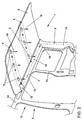
- an air supply device 1 is shown schematically in a perspective view, wherein the individual parts of the air supply device 1 are arranged in an exploded view.
- the air supply device comprises an air duct 2, which can be coupled to air distribution ducts 4 via air duct duct connection elements 3 designed as connecting stubs.
- the two air distribution channels 4 Luftausströmerdüsen 5 are assigned, which are arranged in the mounted state of the air supply device 1 on a headliner side of a headliner 6 facing a vehicle interior 7.
- an air duct element 9 is provided, wherein here two different variants of the air duct element 9 and 9 'are shown.
- the air duct element 9 ' consists of two individual parts, so that a simple and flexible coupling of the ventilation source 8 to the air duct 2 by means of the air duct element 9 or 9' can be produced depending on, for example, a wheelbase of a vehicle in which the air supply device 1 is mounted ,
- the headliner 6 may be formed for a simple and inexpensive embodiment by a flexible flat wood fiber plate, in the recesses on the one hand Beerausströmerdüse recesses 10 and on the other hand as Dachhimmelaus principle 11, which are used for the production of a plug-in and sliding connection during assembly of the air duct 2 use , are punched out.
- connection element recess openings 17 are provided in the headliner 6.
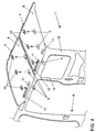
- FIG. 2 the air supply device 1 in the assembled state in a vehicle 13 is shown schematically and in perspective.
- the illustrated viewing direction corresponds a view from the vehicle interior 7 obliquely upward in the direction of a roof rail 14 of the vehicle 13.
- only one side part 15 is shown with the corresponding roof rail 14 of the vehicle 13.
- the air duct element 9 which is coupled to the ventilation source 8 not shown here, arranged, which is coupled in the region of the roof rail 14 to the air duct 2 in terms of flow.
- the air duct 2 extends on the headliner underside of the headlining 6 in the vehicle longitudinal direction, wherein the air duct connecting elements 3 protrude through the connection element recess openings 17 in the headliner 6.
- the air duct 2 is arranged laterally in the vehicle 13 in the region of the roof rail 14 so that the loading height or the headroom of the vehicle interior 7 in the areas relevant thereto, in particular in the region of the vehicle longitudinal center, is not restricted by the air duct 2 arranged inside the vehicle interior 7 ,
- the two air distribution channels 4 are each arranged extending in the vehicle transverse direction over the entire vehicle width, wherein the air distribution channels 4 are arranged on the headliner top, that the Heilausströmerdüse recesses 10 are covered by the air distribution channels 4.
- a fixing screw 18 is provided, which forms a fuse for the air duct 2 in the assembled state in addition to the plug-in and sliding connection between the air duct 2 and headliner 6.
- Arrows 19 the air flow path in Fig. 2 is located.
- the air in the region of the D-pillar 16 flows vertically upward through the air duct element 9 and is deflected in the region of the roof rail 14 into the air duct 2.
- the air flows in the vehicle longitudinal direction extending respectively to the air duct connection elements 3 and of these in the associated air distribution channels 4.
- the air distribution ducts 4 the air flow is distributed over the entire vehicle width and can flow through the Luftausströmerdüsen 6 in the vehicle interior 7.
- FIG. 3 is a schematic sectional view through an air distribution channel 4 is shown.
- the air distribution channel 4 has seen in cross section a downwardly open hat-shaped profile with mounting flanges 20, wherein the mounting flanges 20 are connected to the headliner top side of the headliner 6 by gluing and / or merging and / or tacking and / or welding.
- the headliner top forms a wall portion of the air distribution duct 4, so that the air distribution channel 4 can be produced inexpensively as a simple component, for example by deep drawing.
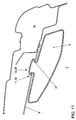
- a partial region of the air supply device 1 is shown schematically and in perspective, only the assembly of Heilausströmerdüsen 5 is to be explained on the headliner 6 here.
- the two air distribution channels 4 are mounted in the region of the Luftausströmerdüse recesses 10, so that the Heilausströmerdüsen 5 from the vehicle interior 7 can be easily clipped into the Heilausströmerdüse recesses 10.
- the Heilausströmerdüsen 5 can also be mounted by a screw or by a bond to the headliner 6.
- connection element recess opening 17 In the lateral edge region of the headliner 6, which is associated with the roof rail 14, also the other punched-outs in the headliner 6 can be seen, namely in the direction of travel from front to back a connection element recess opening 17, a roof lining 11, a connection element recess opening 17 with a headliner recess 11 is combined, and in the region of the D-pillar 16 again a headliner recess 11th
- a partial region of the air supply device 1 is shown schematically and in perspective, in which case the assembly of the air duct element 9 is to be shown.
- plastic moldings 21 are arranged, to which corresponding recesses 22 are assigned to the D pillar 16.
- the air channel element 9 can be easily inserted into the ventilation source 8 accordingly and also be clipped with the plastic moldings 21 in the associated recesses 22 on the D-pillar 16.
- the air channel element 9 can be mounted quickly and easily, but nevertheless functionally reliable on the D-pillar 16.
- the corresponding assembly sequence in Fig. 5 is located.
- FIG. 6 shows a schematic sectional view through the air duct element 9 in the region of the plastic molding 21 in the mounted state. It can be seen that the plastic molding 21 is formed so that in the assembled state, a rear engagement of the plastic molding 21 in the recess 22 takes place. Thus, the air duct element 9 is securely held on the D-pillar 16 while driving.
- Fig. 7 and 8 the assembly steps for mounting the air duct 2 on the headliner 6 are shown.
- the air duct 2 is inserted with one end into the air duct element 9 (arrow 24) and then the air duct 2 is pivoted in the direction of roof rail 14 (arrow 25).
- the air duct connection elements 3 engage in the correspondingly associated connection element recess openings 17 and the bolts 12 in the correspondingly associated Dachhimmelaus traditions 11 a.
- To complete the plug and slide connection of the air duct 2 is then moved in the direction of air duct element 9, as shown in Fig. 8 (arrow 26).
- the fixing screw 18, which is arranged in the end region of the air duct 2 can be screwed.
- FIGS. 9 and 10 the production of a plug and slide connection is explained in detail in an exemplary manner.
- the bolt 12 By pivoting done during assembly of the air duct 2 (arrow 25 in Fig. 7), the bolt 12 is inserted into the correspondingly associated Dachhimmelaus principleung 11.
- the headliner recess 11 is keyhole-shaped and has a bolt receptacle 29 and an adjoining, narrower and dimensioned approximately in the stud web 27 adapted groove-shaped slot portion 30 on ,
- the bolt 12 protrudes with the bolt head 28 in the area of the bolt receptacle 29 through the headliner 6 and then by moving the air duct 2 (arrow 26 in Fig.
- Fig. 11 is a schematic sectional view through the air duct 2 in the region of the bolt 12 is shown in the assembled state. In this case, the engaging behind the bolt head 28 in the slot portion 30 of the headliner recess 11 can be seen.
- the bolt 12 may be spaced from an air duct connecting element 3 on the air duct 2 executed. Furthermore, it is possible to arrange the bolt 12 in the region of the air duct connection element 3, as shown schematically and in perspective in a view obliquely from above in FIG. 12.
- the air duct 2 is shown in the assembled state on the headliner 6, so that the bolt head 28, the slot portion 30 of the headliner recess 11, which is combined in this embodiment with the connection element recess opening 17, engages behind.
- the air duct connection element 3 is arranged, which protrudes through the connection element recess opening 17 and thus establishes a fluid connection between the air duct 2 and the air distribution duct 4 (not shown here).
- a fixing lug 32 is arranged on the air duct connection element 3, which cooperates in the assembled state of the air duct 2 with the opening edge region of the connection element recess opening 17, so that a displacement of the air duct 2 is blocked accordingly. If the air duct 2 to be dismantled again, the air duct 2 can be easily pivoted away from the headliner 6, so that thereby the fixing lug 32 is pivoted away from the opening edge region of the connecting element recess opening 17 with.
- a seal 33 is shown in broken lines in Fig. 12, which is arranged between the headliner 6 on the headliner side and the air duct 2 circumferentially around the air duct connection element 3.
- the connection area between the air duct 2 and the air distribution duct 4 is sealed, wherein in addition a corresponding rattle freedom between the air duct 2 and the headliner 6 can be ensured by the seal 33.
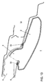
- FIG. 13 schematically shows a sectional view through the air duct 2 in the region of an air duct connection element 3 in the mounted state.
- the installation position of the seal 33 can be seen, which is tightly compressed between the headliner 6 and the corresponding outer wall region of the air duct 2.
- the seal 33 can be preassembled either circumferentially on the roof-opening-side recess opening edge area of the connection-element recess opening 17 or on the air-duct 2 in the region of the air-duct connection element 3.
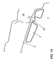
- Fig. 14 is a schematic sectional view through the air duct 2 in the region of the fixing screw 18 shown in the assembled state.
- the fixing screw 18 can be screwed into the roof rail 14.
- the arrangement of the fixing screw 18 on the air duct 2 is advantageously carried out in the end region of the air duct 2, which faces the connection region to the air duct element 9 (see Fig. 8).
- an air supply device 1 which consists of a few and inexpensive to produce components.
- a simple assembly of the individual components is possible in particular by producing plug-in and sliding connections.
Landscapes
- Physics & Mathematics (AREA)
- Thermal Sciences (AREA)
- Engineering & Computer Science (AREA)
- Mechanical Engineering (AREA)
- Air-Conditioning For Vehicles (AREA)
- Duct Arrangements (AREA)
Claims (22)
- Dispositif d'alimentation en air (1) pour climatiser l'habitacle (7) d'un véhicule (13), notamment d'un véhicule utilitaire,
comprenant un habillage de plafond (6) pouvant être disposé dans un habitacle du véhicule, et, disposé sur le côté supérieur de d'habillage de plafond tourné vers le plafond du véhicule dans l'état monté, au moins un canal de distribution d'air (4) pouvant être accouplé à une source de ventilation, lequel s'étend sur au moins une région partielle du côté supérieur de l'habillage du plafond et la recouvre, au moins une buse de sortie d'air étant prévue dans l'habillage du plafond (6) dans la région partielle recouverte du côté supérieur de l'habillage du plafond, pour un passage d'air dans l'habitacle du véhicule, et comprenant un canal de guidage d'air (2) qui est accouplé directement ou indirectement à la source de ventilation (8) et, au moyen d'au moins un élément de raccordement de canal de guidage d'air (3), à l'au moins un canal de distribution d'air (4) sur le côté supérieur de l'habillage du plafond,
caractérisé en ce que
le canal de guidage d'air (2) s'étend dans l'état monté avec un côté longitudinal de canal de guidage d'air le long d'un côté inférieur de l'habillage de plafond tourné vers l'habitacle du véhicule (7). - Dispositif d'alimentation en air selon la revendication 1, caractérisé en ce que l'au moins un élément de raccordement de canal de guidage d'air (3) est guidé par des ouvertures d'évidement correspondantes de l'élément de raccordement (17) dans l'habillage du plafond (6) de préférence par engagement positif et/ou de manière étanche et est accouplé au canal de distribution d'air (4).
- Dispositif d'alimentation en air selon la revendication 1 ou 2, caractérisé en ce que le canal de guidage d'air (2) peut être encliqueté ou verrouillé de préférence de manière desserrable au moyen d'au moins une connexion rapide réalisée sous forme de connexion par encliquetage et/ou par enfichage et/ou par coulissement sur l'habillage de plafond (6).
- Dispositif d'alimentation en air selon la revendication 3, caractérisé en ce que le canal de guidage d'air (2) peut être verrouillé au moyen d'au moins une connexion par enfichage et par coulissement sur l'habillage du plafond (6), de telle sorte qu'un boulon (12) soit prévu sur le canal de guidage d'air (2) pour réaliser la connexion en question par enfichage et coulissement, lequel présente une tige de boulon (27) et une tête de boulon (28) plus large par comparaison, le boulon (12) pouvant être enfoncé avec la tête de boulon (28) à travers un logement de boulon (29), du côté de l'habillage du plafond, d'un évidement de l'habillage du plafond (11) en forme de trou de serrure, auquel se raccorde une région de fente (30) en forme de rainure plus étroite que la tête de boulon (28) et de dimensions adaptées approximativement à la tige de boulon (27) de sorte qu'ensuite le boulon (12) avec sa tige de boulon (27), de préférence avec une fermeture par serrage et/ou avec une fermeture par engagement positif, puisse être enfoncé depuis le logement de boulon (29) dans région de fente (30) et que la tête de boulon (28) vienne en prise par l'arrière dans la région de fente dans sa position finale de déplacement avec l'évidement de l'habillage du plafond (11).
- Dispositif d'alimentation en air selon la revendication 4, caractérisé en ce que dans la région du boulon (12) est en outre prévu au moins un ergot de fixation (32) qui peut être introduit de préférence de manière desserrable après un transfert du boulon (12) dans sa position finale de déplacement dans la région d'évidement de l'habillage du plafond, de préférence dans la région du logement de boulon (29), de préférence par insertion et/ou pivotement de telle sorte que l'ergot de fixation (32), en coopérant avec un élément conjugué du côté de l'évidement de l'habillage du plafond, de préférence une région de bord d'ouverture, bloque un déplacement du boulon (12) et donc du canal de guidage d'air (2).
- Dispositif d'alimentation en air selon la revendication 4 ou 5, caractérisé en ce que la connexion par enfichage et par coulissement est réalisée sur le canal de guidage d'air (2) dans la région de l'élément de raccordement de canal de guidage d'air (3).
- Dispositif d'alimentation en air selon l'une quelconque des revendications 4 à 6, caractérisé en ce que la connexion par enfichage et par coulissement est prévue au niveau d'une région de la paroi extérieure du canal de guidage d'air (2) qui est espacée de l'au moins un élément de raccordement de canal de guidage d'air (3).
- Dispositif d'alimentation en air selon l'une quelconque des revendications 3 à 7, caractérisé en ce que le canal de guidage d'air (2), après la fabrication de la connexion rapide à l'habillage du plafond (6), peut être fixé au moyen d'au moins un élément de fixation (18) à l'habillage du plafond (6), de préférence dans la région d'une extrémité du canal de guidage d'air libre opposée à la source de ventilation (8).
- Dispositif d'alimentation en air selon la revendication 2 et selon l'une quelconque des revendications 3 à 8, caractérisé en ce qu'un joint d'étanchéité (33) annulaire guidé tout autour de l'élément de raccordement de canal de guidage d'air (3) est prévu, lequel s'applique de manière pressée hermétiquement dans l'état monté d'une part contre une région de bord de l'ouverture de logement du côté inférieur de l'habillage de plafond et d'autre part contre une région de canal de guidage d'air associée de manière correspondante, de préférence une région de paroi extérieure du canal de guidage d'air (2).
- Dispositif d'alimentation en air selon la revendication 2 et selon l'une quelconque des revendications 3 à 9, caractérisé en ce que l'au moins un élément de raccordement de canal de guidage d'air (3) est réalisé par un raccord qui présente de préférence une section transversale rectangulaire.
- Dispositif d'alimentation en air selon l'une quelconque des revendications 1 à 10, caractérisé en ce que le canal de guidage d'air (2) s'étend dans l'état monté dans l'habitacle du véhicule (7) sur le côté inférieur de l'habillage du plafond du côté du bord dans la région proche du longeron du toit (14) dans la direction longitudinale du véhicule, de préférence dans la région arrière du véhicule.
- Dispositif d'alimentation en air selon la revendication 11, caractérisé en ce que le canal de guidage d'air (2) s'étend de préférence dans la région arrière du véhicule d'un véhicule break ou utilitaire, jusqu'à environ la région d'une colonne verticale, de préférence une colonne D (16), et est accouplé à une source de ventilation (8) s'y trouvant, de préférence une soufflante, notamment au moyen d'au moins un élément de canal d'air (9 ; 9') s'étendant le long de la colonne verticale (16) et/ou d'une région d'extrémité de longeron de toit dans la direction longitudinale du véhicule.
- Dispositif d'alimentation en air selon la revendication 12, caractérisé en ce que l'élément de canal d'air (9 ; 9') reliant la source de ventilation (8) au canal de guidage d'air (2) peut être encliqueté au niveau de la colonne D (16) au moyen d'au moins une connexion par encliquetage et/ou par coulissement et/ou par enfichage en tant que connexion rapide, de préférence des formations en plastique (21) sur l'élément de canal d'air (9 ; 9') venant en prise par l'arrière au moyen d'évidements (22) dans la colonne (16).
- Dispositif d'alimentation en air selon l'une quelconque des revendications 1 à 13, caractérisé en ce que l'au moins un canal de distribution d'air (4) disposé du côté supérieur de l'habillage du plafond s'étend sur l'habillage du plafond (6) entre des côtés opposés du véhicule dans la direction transversale du véhicule, de préférence dans une région du toit du véhicule non renforcée.
- Dispositif d'alimentation en air selon la revendication 2 et selon l'une quelconque des revendications 3 à 14, caractérisé en ce que l'on prévoit sur le côté supérieur de l'habillage du plafond au moins deux canaux de distribution d'air (4) qui sont orientés de manière espacée l'un de l'autre et approximativement parallèlement l'un à l'autre et qui s'étendent dans la direction transversale du véhicule entre des côtés opposés du véhicule du côté supérieur de l'habillage du plafond, et
en ce que chacun de ces canaux de distribution d'air séparés (4) est connecté fluidiquement au canal de guidage d'air (2) au moyen d'un élément de raccordement de canal de guidage d'air (3) séparé. - Dispositif d'alimentation en air selon l'une quelconque des revendications 1 à 15, caractérisé en ce que le canal de distribution d'air (4) présente en section transversale un profil ouvert vers le bas, de préférence en forme de U et/ou en forme de chapeau, avec des brides de fixation (20) au niveau des extrémités libres de telle sorte que la région recouverte du côté supérieur de l'habillage du plafond fasse partie du guidage d'air du côté supérieur.
- Dispositif d'alimentation en air selon l'une quelconque des revendications 1 à 16, caractérisé en ce que l'au moins un canal de distribution d'air (4) est connecté au côté supérieur de l'habillage du plafond par collage et/ou fusion et/ou adhésion et/ou soudage.
- Dispositif d'alimentation en air selon l'une quelconque des revendications 1 à 17, caractérisé en ce que l'au moins un canal de distribution d'air (4) est fabriqué à partir d'un matériau flexible en carton et/ou en carte et/ou en fibre de bois et/ou en plastique, de préférence une mousse de plastique, de préférence une mousse de polyéthylène.
- Dispositif d'alimentation en air selon l'une quelconque des revendications 1 à 18, caractérisé en ce que le canal de guidage d'air (4) avec éventuellement des éléments de canal d'air accouplés (9 ; 9'), pour le raccordement à une source de ventilation (8), est fabriqué d'une seule pièce sous forme de pièce soufflée en plastique, de préférence sous forme de pièce soufflée en plastique grainé, de préférence en polypropylène.
- Dispositif d'alimentation en air selon l'une quelconque des revendications 1 à 19, caractérisé en ce que l'habillage du plafond (6) est réalisé sous forme de plaque flexible, plane et de préférence ayant des dimensions stables, de préférence en un matériau en plastique et/ou en carton et/ou en carte et/ou en fibre de bois.
- Dispositif d'alimentation en air selon la revendication 20, caractérisé en ce que les évidements (10 ; 11 ; 17) pour des pièces fonctionnelles et/ou rapportées sont estampées dans l'habillage du plafond (6).
- Dispositif d'alimentation en air selon la revendication 20 ou 21, caractérisé en ce que l'habillage du plafond (6), de préférence la partie de l'habillage du plafond prévue pour la région arrière, est réalisé(e) en plusieurs parties.
Applications Claiming Priority (2)
| Application Number | Priority Date | Filing Date | Title |
|---|---|---|---|
| DE10347308 | 2003-10-08 | ||
| DE10347308A DE10347308A1 (de) | 2003-10-08 | 2003-10-08 | Luftversorgungseinrichtung zur Klimatisierung eines Fahrzeuginnenraums eines Fahrzeugs, insbesondere eines Nutzfahrzeuges |
Publications (2)
| Publication Number | Publication Date |
|---|---|
| EP1522437A1 EP1522437A1 (fr) | 2005-04-13 |
| EP1522437B1 true EP1522437B1 (fr) | 2006-12-27 |
Family
ID=34306374
Family Applications (1)
| Application Number | Title | Priority Date | Filing Date |
|---|---|---|---|
| EP04021650A Expired - Lifetime EP1522437B1 (fr) | 2003-10-08 | 2004-09-11 | Dispositif d'alimentation en air pour climatiser l'habitacle d'un véhicule, en particulier d'un véhicule utilitaire |
Country Status (3)
| Country | Link |
|---|---|
| EP (1) | EP1522437B1 (fr) |
| AT (1) | ATE349346T1 (fr) |
| DE (2) | DE10347308A1 (fr) |
Families Citing this family (7)
| Publication number | Priority date | Publication date | Assignee | Title |
|---|---|---|---|---|
| DE102005031875B4 (de) * | 2005-07-07 | 2013-05-29 | Webasto Ag | Dachmodul mit Belüftungskanal |
| DE102008013450B4 (de) | 2008-03-10 | 2023-08-03 | Volkswagen Ag | Fahrgastraumklimatisierung in einem Fahrzeug und Wärmeaustauscher-Einrichtung dafür |
| DE102008024430B4 (de) | 2008-05-20 | 2017-03-02 | Dr. Ing. H.C. F. Porsche Aktiengesellschaft | Kraftfahrzeug mit Luftkanalabschnitten für die Klimatisierung des Fahrzeuginnenraums |
| JP6449719B2 (ja) * | 2015-05-27 | 2019-01-09 | ヤンマー株式会社 | 作業車 |
| DE102016205254B4 (de) * | 2016-03-30 | 2018-11-15 | Volkswagen Aktiengesellschaft | Luftführungseinrichtung, bodenseitiges Luftführungssystem und Kraftfahrzeug |
| DE102018222502A1 (de) * | 2018-12-20 | 2020-06-25 | Continental Engineering Services Gmbh | Belüftungssystem für eine lokal anpassbare Temperaturzone in einem Fahrgastraum |
| DE102020208217A1 (de) | 2020-07-01 | 2022-01-05 | Volkswagen Aktiengesellschaft | Fahrzeug mit einer Luftversorgungseinrichtung |
Family Cites Families (9)
| Publication number | Priority date | Publication date | Assignee | Title |
|---|---|---|---|---|
| JPS5815204Y2 (ja) * | 1978-04-11 | 1983-03-28 | 日産自動車株式会社 | 車両用空気吹出し装置 |
| JPS60176908U (ja) * | 1984-05-07 | 1985-11-25 | トヨタ自動車株式会社 | ル−フダクトの取付構造 |
| US4893866A (en) * | 1988-06-10 | 1990-01-16 | United Technologies Automotive Inc. | Motor vehicle body structure for receiving snap-fit modular headliner fasteners |
| DE4237344C2 (de) * | 1992-11-05 | 1996-09-19 | Beneform Gmbh | Autohimmel für die Dachinnenverkleidung eines Personenkraftfahrzeugs oder Kleinbusses |
| US6062635A (en) * | 1998-03-20 | 2000-05-16 | Lear Automotive Dearborn, Inc, | Plastic air duct integrated to headliner |
| JP3065584B2 (ja) * | 1998-06-03 | 2000-07-17 | 株式会社オーツカ | 衝撃エネルギーを吸収するエアダクト |
| DE19832738A1 (de) * | 1998-07-21 | 2000-01-27 | Christian P Rassaerts | Fahrgastzelle für ein Transportfahrzeug |
| JP3578952B2 (ja) * | 1999-11-26 | 2004-10-20 | 本田技研工業株式会社 | 車両のエアダクト及びガーニッシュ構造 |
| US20030164219A1 (en) * | 2002-02-20 | 2003-09-04 | Joerg Brahm | Headliner/duct assembly and welding process therefor |
-
2003
- 2003-10-08 DE DE10347308A patent/DE10347308A1/de not_active Withdrawn
-
2004
- 2004-09-11 EP EP04021650A patent/EP1522437B1/fr not_active Expired - Lifetime
- 2004-09-11 AT AT04021650T patent/ATE349346T1/de not_active IP Right Cessation
- 2004-09-11 DE DE502004002426T patent/DE502004002426D1/de not_active Expired - Lifetime
Also Published As
| Publication number | Publication date |
|---|---|
| ATE349346T1 (de) | 2007-01-15 |
| DE10347308A1 (de) | 2005-05-04 |
| EP1522437A1 (fr) | 2005-04-13 |
| DE502004002426D1 (de) | 2007-02-08 |
Similar Documents
| Publication | Publication Date | Title |
|---|---|---|
| DE69420829T2 (de) | Strukturelement für armaturenbrett | |
| DE69002127T2 (de) | Fahrzeugaufbau. | |
| EP3022093B1 (fr) | Tableau de bord d'un vehicule | |
| DE102007036918B4 (de) | Instrumententräger | |
| DE102011009605B4 (de) | Anordnung einer Instrumententafel im Innenraum eines Kraftfahrzeuges | |
| EP1532040A1 (fr) | Carrosserie de voiture a structure portante composee de modules de grandes dimensions | |
| EP2230159B1 (fr) | Elément d'habillage dans une aile de véhicule ayant une connection technique pour écoulement de fluide vers un projecteur | |
| DE19531876A1 (de) | Querträger für die Befestigung des Armaturenbrettes | |
| DE29916467U1 (de) | Instrumententräger | |
| DE102005031875B4 (de) | Dachmodul mit Belüftungskanal | |
| DE202015100493U1 (de) | Quer durch das Fahrzeug verlaufende Strukturstütze mit integriertem HLK-Bodenkanal | |
| EP1522437B1 (fr) | Dispositif d'alimentation en air pour climatiser l'habitacle d'un véhicule, en particulier d'un véhicule utilitaire | |
| DE10219053A1 (de) | Belüftungseinrichtung | |
| DE19620921A1 (de) | Armaturenbrett für ein Kraftfahrzeug | |
| EP1291266B1 (fr) | Poutre hybride pour véhicule automobile | |
| DE10254348B4 (de) | Baugruppe für einen Cockpit-Bereich | |
| DE10062151B4 (de) | Instrumententafel, insbesondere für ein Kraftfahrzeug, mit einem Grundkörper und einer Abdeckung | |
| EP2799265B1 (fr) | Module de châssis de porte pour une porte de véhicule automobile conçue de façon modulaire et porte de véhicule automobile conçue de façon modulaire dotée d'un tel module de châssis de porte | |
| DE10347309B4 (de) | Luftversorgungseinrichtung zur Klimatisierung eines Fahrzeuginneraums eines Fahrzeugs, insbesondere eines Nutzfahrzeuges | |
| EP1957299B1 (fr) | Dispositif pour raccorder des conduites d'air, porte de vehicule automobile, colonne de vehicule automobile, et element d'habillage interieur de vehicule automobile | |
| DE10347847B3 (de) | Kraftwagenkarosserie mit zentraler Tragsäule | |
| DE102013013363A1 (de) | Halteanordnung einer Instrumententafel an einem Querträger für einen Kraftwagen | |
| DE102005010161A1 (de) | Bauteil für einen Träger eines Fahrzeugs | |
| EP0891892B1 (fr) | Panneau de garniture en matière thermoplastique pour porte de véhicule automobile obtenu par moulage par soufflage | |
| DE3210019A1 (de) | Gehaeuse fuer eine heizungs- oder klimaanlage fuer kraftfahrzeuge |
Legal Events
| Date | Code | Title | Description |
|---|---|---|---|
| PUAI | Public reference made under article 153(3) epc to a published international application that has entered the european phase |
Free format text: ORIGINAL CODE: 0009012 |
|
| AK | Designated contracting states |
Kind code of ref document: A1 Designated state(s): AT BE BG CH CY CZ DE DK EE ES FI FR GB GR HU IE IT LI LU MC NL PL PT RO SE SI SK TR |
|
| AX | Request for extension of the european patent |
Extension state: AL HR LT LV MK |
|
| 17P | Request for examination filed |
Effective date: 20051013 |
|
| AKX | Designation fees paid |
Designated state(s): AT BE BG CH CY CZ DE DK EE ES FI FR GB GR HU IE IT LI LU MC NL PL PT RO SE SI SK TR |
|
| GRAP | Despatch of communication of intention to grant a patent |
Free format text: ORIGINAL CODE: EPIDOSNIGR1 |
|
| GRAS | Grant fee paid |
Free format text: ORIGINAL CODE: EPIDOSNIGR3 |
|
| GRAA | (expected) grant |
Free format text: ORIGINAL CODE: 0009210 |
|
| AK | Designated contracting states |
Kind code of ref document: B1 Designated state(s): AT BE BG CH CY CZ DE DK EE ES FI FR GB GR HU IE IT LI LU MC NL PL PT RO SE SI SK TR |
|
| PG25 | Lapsed in a contracting state [announced via postgrant information from national office to epo] |
Ref country code: IT Free format text: LAPSE BECAUSE OF FAILURE TO SUBMIT A TRANSLATION OF THE DESCRIPTION OR TO PAY THE FEE WITHIN THE PRESCRIBED TIME-LIMIT;WARNING: LAPSES OF ITALIAN PATENTS WITH EFFECTIVE DATE BEFORE 2007 MAY HAVE OCCURRED AT ANY TIME BEFORE 2007. THE CORRECT EFFECTIVE DATE MAY BE DIFFERENT FROM THE ONE RECORDED. Effective date: 20061227 Ref country code: NL Free format text: LAPSE BECAUSE OF FAILURE TO SUBMIT A TRANSLATION OF THE DESCRIPTION OR TO PAY THE FEE WITHIN THE PRESCRIBED TIME-LIMIT Effective date: 20061227 Ref country code: SK Free format text: LAPSE BECAUSE OF FAILURE TO SUBMIT A TRANSLATION OF THE DESCRIPTION OR TO PAY THE FEE WITHIN THE PRESCRIBED TIME-LIMIT Effective date: 20061227 Ref country code: SI Free format text: LAPSE BECAUSE OF FAILURE TO SUBMIT A TRANSLATION OF THE DESCRIPTION OR TO PAY THE FEE WITHIN THE PRESCRIBED TIME-LIMIT Effective date: 20061227 Ref country code: FI Free format text: LAPSE BECAUSE OF FAILURE TO SUBMIT A TRANSLATION OF THE DESCRIPTION OR TO PAY THE FEE WITHIN THE PRESCRIBED TIME-LIMIT Effective date: 20061227 Ref country code: RO Free format text: LAPSE BECAUSE OF FAILURE TO SUBMIT A TRANSLATION OF THE DESCRIPTION OR TO PAY THE FEE WITHIN THE PRESCRIBED TIME-LIMIT Effective date: 20061227 Ref country code: CZ Free format text: LAPSE BECAUSE OF FAILURE TO SUBMIT A TRANSLATION OF THE DESCRIPTION OR TO PAY THE FEE WITHIN THE PRESCRIBED TIME-LIMIT Effective date: 20061227 Ref country code: DK Free format text: LAPSE BECAUSE OF FAILURE TO SUBMIT A TRANSLATION OF THE DESCRIPTION OR TO PAY THE FEE WITHIN THE PRESCRIBED TIME-LIMIT Effective date: 20061227 Ref country code: PL Free format text: LAPSE BECAUSE OF FAILURE TO SUBMIT A TRANSLATION OF THE DESCRIPTION OR TO PAY THE FEE WITHIN THE PRESCRIBED TIME-LIMIT Effective date: 20061227 Ref country code: IE Free format text: LAPSE BECAUSE OF FAILURE TO SUBMIT A TRANSLATION OF THE DESCRIPTION OR TO PAY THE FEE WITHIN THE PRESCRIBED TIME-LIMIT Effective date: 20061227 |
|
| REG | Reference to a national code |
Ref country code: GB Ref legal event code: FG4D Free format text: NOT ENGLISH |
|
| REG | Reference to a national code |
Ref country code: IE Ref legal event code: FG4D Free format text: LANGUAGE OF EP DOCUMENT: GERMAN |
|
| REF | Corresponds to: |
Ref document number: 502004002426 Country of ref document: DE Date of ref document: 20070208 Kind code of ref document: P |
|
| PG25 | Lapsed in a contracting state [announced via postgrant information from national office to epo] |
Ref country code: SE Free format text: LAPSE BECAUSE OF FAILURE TO SUBMIT A TRANSLATION OF THE DESCRIPTION OR TO PAY THE FEE WITHIN THE PRESCRIBED TIME-LIMIT Effective date: 20070327 Ref country code: BG Free format text: LAPSE BECAUSE OF FAILURE TO SUBMIT A TRANSLATION OF THE DESCRIPTION OR TO PAY THE FEE WITHIN THE PRESCRIBED TIME-LIMIT Effective date: 20070327 |
|
| PG25 | Lapsed in a contracting state [announced via postgrant information from national office to epo] |
Ref country code: ES Free format text: LAPSE BECAUSE OF FAILURE TO SUBMIT A TRANSLATION OF THE DESCRIPTION OR TO PAY THE FEE WITHIN THE PRESCRIBED TIME-LIMIT Effective date: 20070407 |
|
| PG25 | Lapsed in a contracting state [announced via postgrant information from national office to epo] |
Ref country code: PT Free format text: LAPSE BECAUSE OF FAILURE TO SUBMIT A TRANSLATION OF THE DESCRIPTION OR TO PAY THE FEE WITHIN THE PRESCRIBED TIME-LIMIT Effective date: 20070528 |
|
| NLV1 | Nl: lapsed or annulled due to failure to fulfill the requirements of art. 29p and 29m of the patents act | ||
| GBV | Gb: ep patent (uk) treated as always having been void in accordance with gb section 77(7)/1977 [no translation filed] |
Effective date: 20061227 |
|
| EN | Fr: translation not filed | ||
| REG | Reference to a national code |
Ref country code: IE Ref legal event code: FD4D |
|
| PLBE | No opposition filed within time limit |
Free format text: ORIGINAL CODE: 0009261 |
|
| STAA | Information on the status of an ep patent application or granted ep patent |
Free format text: STATUS: NO OPPOSITION FILED WITHIN TIME LIMIT |
|
| PG25 | Lapsed in a contracting state [announced via postgrant information from national office to epo] |
Ref country code: GB Free format text: LAPSE BECAUSE OF FAILURE TO SUBMIT A TRANSLATION OF THE DESCRIPTION OR TO PAY THE FEE WITHIN THE PRESCRIBED TIME-LIMIT Effective date: 20061227 |
|
| 26N | No opposition filed |
Effective date: 20070928 |
|
| BERE | Be: lapsed |
Owner name: VOLKSWAGEN AG Effective date: 20070930 |
|
| PG25 | Lapsed in a contracting state [announced via postgrant information from national office to epo] |
Ref country code: MC Free format text: LAPSE BECAUSE OF NON-PAYMENT OF DUE FEES Effective date: 20070930 Ref country code: FR Free format text: LAPSE BECAUSE OF FAILURE TO SUBMIT A TRANSLATION OF THE DESCRIPTION OR TO PAY THE FEE WITHIN THE PRESCRIBED TIME-LIMIT Effective date: 20070817 Ref country code: GR Free format text: LAPSE BECAUSE OF FAILURE TO SUBMIT A TRANSLATION OF THE DESCRIPTION OR TO PAY THE FEE WITHIN THE PRESCRIBED TIME-LIMIT Effective date: 20070328 |
|
| PG25 | Lapsed in a contracting state [announced via postgrant information from national office to epo] |
Ref country code: BE Free format text: LAPSE BECAUSE OF NON-PAYMENT OF DUE FEES Effective date: 20070930 |
|
| PG25 | Lapsed in a contracting state [announced via postgrant information from national office to epo] |
Ref country code: FR Free format text: LAPSE BECAUSE OF FAILURE TO SUBMIT A TRANSLATION OF THE DESCRIPTION OR TO PAY THE FEE WITHIN THE PRESCRIBED TIME-LIMIT Effective date: 20061227 Ref country code: AT Free format text: LAPSE BECAUSE OF NON-PAYMENT OF DUE FEES Effective date: 20070911 |
|
| PG25 | Lapsed in a contracting state [announced via postgrant information from national office to epo] |
Ref country code: EE Free format text: LAPSE BECAUSE OF FAILURE TO SUBMIT A TRANSLATION OF THE DESCRIPTION OR TO PAY THE FEE WITHIN THE PRESCRIBED TIME-LIMIT Effective date: 20061227 |
|
| REG | Reference to a national code |
Ref country code: CH Ref legal event code: PL |
|
| PG25 | Lapsed in a contracting state [announced via postgrant information from national office to epo] |
Ref country code: LI Free format text: LAPSE BECAUSE OF NON-PAYMENT OF DUE FEES Effective date: 20070930 Ref country code: CH Free format text: LAPSE BECAUSE OF NON-PAYMENT OF DUE FEES Effective date: 20070930 |
|
| PG25 | Lapsed in a contracting state [announced via postgrant information from national office to epo] |
Ref country code: LU Free format text: LAPSE BECAUSE OF NON-PAYMENT OF DUE FEES Effective date: 20070911 Ref country code: CY Free format text: LAPSE BECAUSE OF FAILURE TO SUBMIT A TRANSLATION OF THE DESCRIPTION OR TO PAY THE FEE WITHIN THE PRESCRIBED TIME-LIMIT Effective date: 20061227 |
|
| PG25 | Lapsed in a contracting state [announced via postgrant information from national office to epo] |
Ref country code: HU Free format text: LAPSE BECAUSE OF FAILURE TO SUBMIT A TRANSLATION OF THE DESCRIPTION OR TO PAY THE FEE WITHIN THE PRESCRIBED TIME-LIMIT Effective date: 20070628 Ref country code: TR Free format text: LAPSE BECAUSE OF FAILURE TO SUBMIT A TRANSLATION OF THE DESCRIPTION OR TO PAY THE FEE WITHIN THE PRESCRIBED TIME-LIMIT Effective date: 20061227 |
|
| PG25 | Lapsed in a contracting state [announced via postgrant information from national office to epo] |
Ref country code: LI Free format text: LAPSE BECAUSE OF NON-PAYMENT OF DUE FEES Effective date: 20080930 Ref country code: CH Free format text: LAPSE BECAUSE OF NON-PAYMENT OF DUE FEES Effective date: 20080930 |
|
| REG | Reference to a national code |
Ref country code: DE Ref legal event code: R084 Ref document number: 502004002426 Country of ref document: DE |
|
| REG | Reference to a national code |
Ref country code: DE Ref legal event code: R085 Ref document number: 502004002426 Country of ref document: DE |
|
| P01 | Opt-out of the competence of the unified patent court (upc) registered |
Effective date: 20230523 |
|
| PGFP | Annual fee paid to national office [announced via postgrant information from national office to epo] |
Ref country code: DE Payment date: 20230930 Year of fee payment: 20 |
|
| REG | Reference to a national code |
Ref country code: DE Ref legal event code: R071 Ref document number: 502004002426 Country of ref document: DE |