EP1522455B1 - Vorrichtung zur Festlegung und/oder Positionierung von Gegenständen in einem Transportbehälter - Google Patents
Vorrichtung zur Festlegung und/oder Positionierung von Gegenständen in einem Transportbehälter Download PDFInfo
- Publication number
- EP1522455B1 EP1522455B1 EP04023739A EP04023739A EP1522455B1 EP 1522455 B1 EP1522455 B1 EP 1522455B1 EP 04023739 A EP04023739 A EP 04023739A EP 04023739 A EP04023739 A EP 04023739A EP 1522455 B1 EP1522455 B1 EP 1522455B1
- Authority
- EP
- European Patent Office
- Prior art keywords
- structural parts
- legs
- transport container
- long
- locking
- Prior art date
- Legal status (The legal status is an assumption and is not a legal conclusion. Google has not performed a legal analysis and makes no representation as to the accuracy of the status listed.)
- Expired - Lifetime
Links
- 230000007246 mechanism Effects 0.000 claims abstract description 26
- 238000006073 displacement reaction Methods 0.000 claims description 7
- 230000008901 benefit Effects 0.000 description 3
- 238000010276 construction Methods 0.000 description 3
- 230000009471 action Effects 0.000 description 2
- 230000008859 change Effects 0.000 description 2
- 230000000994 depressogenic effect Effects 0.000 description 2
- 239000007787 solid Substances 0.000 description 2
- 230000001133 acceleration Effects 0.000 description 1
- 230000015572 biosynthetic process Effects 0.000 description 1
- 230000006835 compression Effects 0.000 description 1
- 238000007906 compression Methods 0.000 description 1
- 230000001419 dependent effect Effects 0.000 description 1
- 238000009434 installation Methods 0.000 description 1
- 230000009467 reduction Effects 0.000 description 1
- 239000002356 single layer Substances 0.000 description 1
- 230000007704 transition Effects 0.000 description 1
Images




Classifications
-
- B—PERFORMING OPERATIONS; TRANSPORTING
- B60—VEHICLES IN GENERAL
- B60P—VEHICLES ADAPTED FOR LOAD TRANSPORTATION OR TO TRANSPORT, TO CARRY, OR TO COMPRISE SPECIAL LOADS OR OBJECTS
- B60P7/00—Securing or covering of load on vehicles
- B60P7/06—Securing of load
-
- B—PERFORMING OPERATIONS; TRANSPORTING
- B60—VEHICLES IN GENERAL
- B60P—VEHICLES ADAPTED FOR LOAD TRANSPORTATION OR TO TRANSPORT, TO CARRY, OR TO COMPRISE SPECIAL LOADS OR OBJECTS
- B60P7/00—Securing or covering of load on vehicles
- B60P7/06—Securing of load
- B60P7/135—Securing or supporting by load bracing means
- B60P7/14—Securing or supporting by load bracing means the load bracing means comprising a movable bulkhead
Definitions
- the invention relates to a device of the type specified in the preamble of claim 1 and a transport container equipped with such a device.
- GB-A-14 51 117 devices have already become known ( GB-A-14 51 117 ), the two relatively displaceable, z. B. plate-shaped components, one of which is designed as a mounting element and is attached to a wall of the transport container.
- the other component is designed as a clamping or holding element and arranged in a non-use position in the vicinity of the mounting member, so that between him and one opposite lying wall of the transport container a sufficiently large space for receiving the objects remains. If the charge is secured or positioned in the region of a wall, the holding member is moved against the objects so that they are firmly clamped between the holding member and the opposite wall or positioned at least in a space, which then between the advanced holding member and the opposite lying wall is formed.
- devices of the type described are known ( EP-A-0 737 601 ), in which the two components can be moved by means of a hinge mechanism relative to each other, having a plurality of webs connected to each other like a lattice.
- the end portions of the levers are slidably mounted by means of slides in transversely arranged directions of movement.
- the hinge mechanism is associated with a means for locking the retaining element in a preselected position containing a locking screw or a clamping element.
- This known device is particularly intended for the luggage compartments of passenger cars and also useful in confined spaces, since they can be operated from a front or rear wall of the transport container in contrast to the described, a threaded spindle having device.
- the disadvantage of this device is that it is not sufficiently stable and rigid connection, when it comes to fixing heavy objects with masses of z. B. 200 kg and more.
- the device of the type described above in such a way that they are particularly suitable for use in all-round transport containers such.
- B. lattice boxes od. The like. Is suitable and provided with a hinge mechanism that allows, if necessary, at least to a limited extent, an oblique relative arrangement of the two components to each other.
- the invention has the advantage that the Y-shaped design of the hinge mechanism not only allows a structurally simple, yet stable and torsionally rigid construction of the device, but also other than merely parallel positions of the two components relative to each other.
- the various legs of the hinge mechanism depending on the required stability and torsional rigidity may be formed either as simple, weight-saving rods, but also as a stiffening, frame-shaped or plate-shaped elements. It is particularly advantageous that the two components can be approximated due to the triangular shape of the long legs to a distance to each other, which corresponds to practically the sum of the thicknesses of the legs.
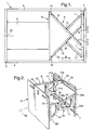
- Fig. 1 shows roughly schematically a transport container 1, z. B. a grid box having a feet supported on the bottom part, a first end wall 2, one of the first end wall 2 opposite and parallel to it, second end wall 3 and the two end walls 2, 3 connecting side parts 4 and 5.
- a schematically indicated object 6 is arranged, which should be determined without slipping for the purpose of transport.
- an in Fig. 1 to 6 provided schematically.
- This contains two z. B. plate-shaped components 7 and 8, which are arranged substantially parallel to each other.
- the component 7 serves as a mounting element and is fastened with fastening elements, not shown, to the inside of the end wall 2.
- the component 7 may be designed to save weight as a rectangular frame, such as Fig. 2 shows, and to have a central recess.
- the other component 8 here has the function of a holding element that presses the article 6 against the inside of the opposite end wall 3 and thereby determines non-slip in the transport container 1.
- the component 8 is therefore preferably a continuous plate.
- the reference numeral 9 hinge mechanism for displacement of the component 8 relative to the component 7 in the direction of a double arrow u is a generally designated by the reference numeral 9 hinge mechanism, which is described below with reference to the Fig. 1 to 6 is explained schematically.
- the hinge mechanism 9 is Y-shaped and has a long leg 10 and a short leg 11.
- the short leg 11 is pivotally connected at one end by a pivot bearing 12 with a central region of the long leg 10 and at an opposite end by another pivot bearing with the component 7.
- the long leg 10 is pivotally mounted at one end on the component 8 by means of a pivot bearing 14 and connected with its other end adjustable with the component 7.
- Adjustable is intended here to mean that the end portion of the leg 10 parallel to a double arrow v, ie perpendicular to the arrow u and perpendicular to the vertical along the component 7 can be moved.
- a second, likewise Y-shaped and essentially identical or structurally identical hinge mechanism 15 is preferably provided, which has a long leg 16 and a short leg 17.
- Analogous to the hinge mechanism 9 of the short leg 17 is connected by a pivot bearing 18 with a central region of the long leg 16 and another pivot bearing with the component 7, while the long leg 16 pivotally connected by a pivot bearing 19 with the component 8 and in the direction of to arrow v parallel arrow w slidably or adjustably connected to the component 7.
- the two hinge mechanisms 9 and 15 are preferably arranged mirror-symmetrically to a parallel to the arrow u center plane 20 of the device.
- the positions of the pivot bearings 14, 19 are selected so that the end portions of the long legs 10, 16 each come to rest on an outer side of the component 8.
- the articulation points for the short legs 11, 17 are respectively located respectively on an outer side of the component 7, such as Fig. 1 to 6 demonstrate.
- the long leg 10 is preferably formed triangular, with a triangle side is pivotally connected to the component 8, while one of this triangle side opposite triangle tip 10a is adjustably mounted on the component 7.
- the short legs 11, 17 are preferably triangular or trapezoidal, wherein in Fig. 2 two pairs of pivot bearings 21a and 21b and 22a and 22b, each with coaxial pivot axes for the legs 11 and 17 can be seen.
- the long and short legs are in particular frame-shaped with particular advantage, ie they are provided with central recesses for weight saving.
- rollers 23, 24 are rotatably mounted, in C-shaped, to the component 8 towards open guide rails 25, 26 can roll off, from which at the top or the lower edge of the frame-shaped component 7 extending transverse struts are formed, said guide rails 25, 26 parallel to the arrows v and w arranged raceways for the rollers 23, 24 form.
- the two parallel components 7, 8 in the use state of the device is substantially vertical and perpendicular to the bottom of the transport container 1 extends.
- the legs 10, 11 and 16, 17 forming plates or frames are arranged with their center planes perpendicular to the bottom of the transport container.
- the guide rails 25, 26 are arranged horizontally parallel to the ground and in use.
- 3 and 4 show the component 8 to move parallel to the arrow u or parallel to the median plane 20, wherein the ends of the long legs 10, 16 and their rollers 23, 24 are moved or adjusted parallel to the arrows v and w respectively. If this reduces the distance of the components 7 and 8, as a comparison of Fig. 1, 2 with the Fig. 3, 4 shows, then the adjustable ends of the legs 10 and 16, which were originally arranged, for example, near the median plane 20 ( Fig. 1 ), further away from this ( Fig. 3 ), while in reverse movement of the rollers 23, 24, the distance of the components 7, 8 is increased.
- Fig. 2 shows an upper edge 27 of the leg 10 between the apex 10a and mounted in the upper guide rail 25 roller 23 and the opposing member 8 extends substantially horizontally, while a lower edge 28 of the leg 10 from the apex 10a from obliquely downward is extended to near the lower edge of the component 8.
- a lower edge 29, starting from the lower mounted roller 24 extends substantially horizontally to the component 8, while an upper edge 30 of the leg 16 from the apex 16a obliquely upward to near the upper edge of the component. 8 extends.
- the two hinge mechanisms 9 and 15 are increasingly swung under reduction of the distance between the two components 7, 8, as the transition from Fig. 3, 4 to Fig. 5, 6 shows, then take the lower edge 28 of the leg 10 and the upper edge 30 of the leg 16 more and more the position of a diagonal to the component 7, as in Fig. 7 is indicated schematically.
- the arrangement is preferably chosen so that the two edges 28, 30 are opposite with a small distance and therefore the two legs 10, 16 are arranged one below the other, so that they can be folded so close to the components 7, 8 until they are arranged practically parallel between them.
- the arrangement is suitably made so that the two short legs 11, 17 during the approach of the components 7 and 8 are increasingly pivoted about the pivot bearings 12, 18 until they are also substantially parallel to the components 7 and 8 and therefore between them and the associated long legs 10, 16 are. This condition is particular in Fig. 5, 6 and 7 shown.
- the device according to the invention therefore reduces the fillable space within the transport container 1 only slightly.
- the pivotally mounted triangle sides of the long legs 10 and 16, which in Fig. 7 are denoted by the reference numerals 10b and 16b, extend over a large part of their height and more than half the height of the component 8, and the same applies after Fig. 2 for the height of those parts of the short legs 11 and 17, which are hinged to the component 7.
- Fig. 8 schematically shows a rear view of the component used as a mounting member 7 without the hinge mechanisms 9, 15 and without the component 8, but with a means for locking the components 7, 8 in the relative positions produced by means of the hinge mechanisms 9, 15. Details of the locking means are in Fig. 9 and 10 shown in two different operating positions.
- the component 7 each includes an upper and lower, formed by the guide rails 25, 26 frame part and two connecting them, in the operating position vertical side parts 33 and 34.
- the upper guide rail 25 is provided with the roller 23 slide 35 and in the lower guide rail 26 a provided with the roller 24 slide 36 slidably mounted.
- the roller 23 is formed in two parts and each provided with an upper and lower roller part 23a, 23b, between which an axis 35a of the carriage 35 is arranged, which serves for the pivotal attachment of the triangle tip 10a of the long leg 10.
- the arrangement is made in the region of the carriage 36, to which the triangular tip 16a of the long leg 16 is fastened.
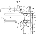
- Fig. 9 and 10 show details of the means for locking the example of the triangle tip 10 a and the attached roller 23 of the long leg 10 after Fig. 2 , where in Fig. 9 a locking position and in Fig. 10 a Entarretier ein is shown.
- the adjustable, long leg 10 can be moved with its end triangle tip 10a and its roller 23 not only in the direction of the double arrow v in the guide rail 25 (see also Fig. 1 ), but that on the underside of the triangle tip 10a and the roller 23, a locking pin 48 is mounted.
- This detent pin 48 serves the purpose of locking into one of the holes 37 of the strip 39 and thereby determine the position of the end portion of the long leg 10 on the component 7 in the direction of the arrow v .
- This detent position is secured by the spring 47 ( Fig. 9 ).
- the actuating rod 41 against the force of the spring 47 down in the off Fig. 10 moved apparent position.
- the attached at 50 to the bar 39 actuating rod 41 takes the bar 39 at her in Fig. 8 right end opposite to the direction of the arrow x , until the Locking pin 48 has emerged from the respective hole 37.
- the leg 10 can be moved parallel to the arrow v when the actuating rod 41 is pressed down until a new desired relative position of the two components 7, 8 is produced.
- the actuating rod 41 is released and thereby pressed under the action of the spring 47 in the direction of arrow x upwards, the locking pin 48 can snap into a hole 37 of the bar 39 again.
- the lower bar 40 ( Fig. 7 and 8th ) is actuated on its right side in a corresponding manner by the actuating rod 41.
- the operating rod 42 serves the purpose of the strips 39, 40 at their in Fig. 8 to actuate left ends in the same way as described above for the right ends.
- both actuating rods 41, 42 are selectively operated together or individually and independently.
- only the actuating rod 42 is analogous to in the embodiment Fig. 9 and 10 preferably only the impeller 24 or the carriage 36 ( Fig. 8 ) released, for which purpose the bar 40 is mounted so pivotable that while the carriage 35 in the off Fig. 9 visible manner remains locked.
- the actuating rod 41 projects with a head piece 41a on the upper guide rail 25 also upwards.
- the head piece 41a is pivotally connected there to one end of a lever 51, to which a slider 52, which is assigned to its actuation and is displaceably mounted on the guide rail 25, is associated.
- the slider 52 is provided with a slot 53 which is penetrated by guide pins 54 which are mounted on the upper side of the guide rail 25, that the slider 52 in the direction of arrow v by a predetermined length by the elongated hole 53 degree back and forth can be moved.
- a control pin 55 is further attached, which engages behind a pawl 56 of the substantially perpendicular to the actuating rod 41 arranged lever 51 and in a locked position according to Fig. 9 at this so rests that the articulated actuating rod 41 can assume their highest position, ie the locking position and at the same time an upper edge 51a of the lever 51 accordingly Fig. 9 is arranged slightly obliquely to the surface of the guide rail 25. If the unlocking position is to be established from this position, the slider 52 is moved into Fig. 9 moved to the right, whereby the control pin 55 runs onto the inclined upper edge 51 a of the lever 51 and thereby gradually depressed it until it is out of Fig. 10 has achieved an apparent unlocking position.
- the invention has the advantage that with simple means a device has been created, which allows a secure fixing of the objects 6 in the transport container 1. If these are objects 6 in which, for their definition, a displacement of the entire component 8 parallel to the arrow u (FIG. Fig. 1 ) are sufficient, based on the Fig. 7 to 10 described slide 52 and 57 simultaneously displaced into the unlocking position, whereby the two strips 39, 40 lifted off over their entire length from the guide rails 25, 26 and thereby the locking pins 48 of both rollers 23, 24 are released. After the desired displacement, the slides 52, 57 are moved back into their locking positions.
- the device of the invention also offers in a particularly advantageous manner the ability to bring the component 8 in an inclined position relative to the other component 7 by only one of the two slides 52, 57 is brought into the Entarret istswolf.
- the two strips 39, 40 only on one side, ie eg in Fig. 8 lifted off to the right or left of the guide rails 25, 26.
- only those locking pins 48 are released, which are located just on this side of the component 7. If the arrangement is appropriate Fig. 2 .
- the first hinge mechanism 9 includes a long leg consisting of two V-shaped rods 61 and 62 fixedly connected to each other in the top of the V-shape and pivotable on the component 8 by means of pivot bearings 63 at their ends remote from the tip are fastened, and a short leg, which consists of two substantially parallel rods 64, 65, whose one ends are pivotally mounted on the same, the pivot bearings 63 opposite side of the component 7.
- the second hinge mechanism 15 includes a long leg, which consists of V-shaped and interconnected at their tips rods 66, 67 whose ends remote from the tip on the side facing away from the pivot bearings 63 of the Component 8 are fixed with pivot bearings 68, and one consisting of substantially parallel rods 69, 70 short leg, which is pivotally mounted at one end to the component 7.
- the short legs are pivotally mounted at their respective other ends by means of a respective pivot axis 71, 72 at a central region of the long legs or the rods 61, 62 and 66, 67.
- the joint mechanisms 9, 10 formed from the long and short legs have the Y-shape characteristic of the invention in plan view.
- the tip-ending adjustment ends of the long legs corresponding to the triangle tips 10a, 16a of FIG Fig. 4 are here provided with Einpreßhülsen 73, in which axially movable, not shown locking pins are mounted. In an axially extended locking position, these locking pins project analogously to the latching pins 48 Fig. 9 in a selected hole 74 formed as a perforated strip, upper or lower frame part 75, 76 of the component 7. For unlocking the locking pins are pulled out of the respective hole 74. For this purpose serve z. B.
- Bowden cables not shown, which are connected on the one hand with the Einpreßbuchsen 73 and the locking pins and on the other hand with an operating lever 77 which is biased by springs, not shown in a locking position.
- This operating lever 77 like the slide 52, 57 after Fig. 8 be pivotally mounted on the component 7.
- An advantageous embodiment provides ( Fig. 12 ), to store the operating lever 77 in an upper region of the displaceable member 8 and to provide this at the same time with grip holes 78, such as Fig. 12 clearly shows. This makes it possible, the component 8, when a change in position is desired, to detect the handle holes 78 and simultaneously extract the locking pins from the holes 74 by means of the operating lever 77.
- the invention is not limited to the described embodiments, which can be modified in many ways.
- the locking means with other, in particular also electrical, electromagnetic, hydraulic, pneumatic or other suitable means for releasing the locking pins 48 from the holes 38 and 74, which may also comprise rotatable spindles.
- the device described can be arranged differently than shown in the transport container.
- the component 7 serving as a mounting element may be attached to a long side 4, 5 (FIG. Fig. 1 ) of the transport container, in which case preferably at least the component 8 serving as the holding element should have a width corresponding to the length of the long side.
- the devices described can also be arranged in a 90 ° about a longitudinal axis 79 (FIG. Fig. 2 ) rotated position inserted into the transport container 1 be, in which case the different pivot axes are arranged substantially horizontally and the serving for actuating the locking means expediently on the then upper side part 33 and 34 ( Fig. 8 ) come to rest.
- the component 7 as a holding element and the component 8 as a mounting element and / or to support the respective movable component for easier mobility on wheels or wheels.
- the invention also includes transport containers, in which the device described is firmly installed. It may be expedient to omit the serving as a mounting member 7 completely and replaced by an appropriately trained, solid wall or the bottom of the respective transport container. This is especially true for a further possible application of the device according to the invention, wherein the component 7 is arranged at the bottom of the transport container 1 and the component 8 serves to be moved more or less vertically upwards. In this case, items to be stored in a lattice box or the like may be positioned at different heights as needed.
- the device according to the invention serves in this case as a displaceable floor, for which reason the component 8 should have a size corresponding to the size of the floor area.
Landscapes
- Engineering & Computer Science (AREA)
- Transportation (AREA)
- Mechanical Engineering (AREA)
- Rigid Containers With Two Or More Constituent Elements (AREA)
- Supplying Of Containers To The Packaging Station (AREA)
- Auxiliary Devices For And Details Of Packaging Control (AREA)
- Warehouses Or Storage Devices (AREA)
- Load-Engaging Elements For Cranes (AREA)
- Handcart (AREA)
- Automatic Assembly (AREA)
- Details Of Rigid Or Semi-Rigid Containers (AREA)
- Buffer Packaging (AREA)
Applications Claiming Priority (4)
| Application Number | Priority Date | Filing Date | Title |
|---|---|---|---|
| DE20315865U | 2003-10-09 | ||
| DE20315865 | 2003-10-09 | ||
| DE202004012593U DE202004012593U1 (de) | 2003-10-09 | 2004-08-09 | Vorrichtung zur Festlegung und/oder Positionierung von Gegenständen in einem Transportbehälter |
| DE202004012593U | 2004-08-09 |
Publications (3)
| Publication Number | Publication Date |
|---|---|
| EP1522455A2 EP1522455A2 (de) | 2005-04-13 |
| EP1522455A3 EP1522455A3 (de) | 2006-12-06 |
| EP1522455B1 true EP1522455B1 (de) | 2009-12-16 |
Family
ID=33521693
Family Applications (1)
| Application Number | Title | Priority Date | Filing Date |
|---|---|---|---|
| EP04023739A Expired - Lifetime EP1522455B1 (de) | 2003-10-09 | 2004-10-06 | Vorrichtung zur Festlegung und/oder Positionierung von Gegenständen in einem Transportbehälter |
Country Status (12)
| Country | Link |
|---|---|
| US (1) | US7322782B2 (da) |
| EP (1) | EP1522455B1 (da) |
| JP (1) | JP2005112473A (da) |
| KR (1) | KR20050034545A (da) |
| CN (1) | CN100478218C (da) |
| AT (1) | ATE452047T1 (da) |
| AU (1) | AU2004218657A1 (da) |
| CA (1) | CA2484348A1 (da) |
| DE (2) | DE202004012593U1 (da) |
| DK (1) | DK1522455T3 (da) |
| ES (1) | ES2338873T3 (da) |
| NO (1) | NO20044273L (da) |
Families Citing this family (16)
| Publication number | Priority date | Publication date | Assignee | Title |
|---|---|---|---|---|
| DE102007007034B4 (de) * | 2007-02-08 | 2010-09-02 | Seebauer, Kurt | Einrichtung zur Ladungssicherung insbesondere für Personenkraftwagen mit einer Ladezone |
| DE202008012869U1 (de) | 2008-09-26 | 2009-01-02 | Css-Patentverwaltungsgesellschaft Mbh | Vorrichtung zur vertikalen Festlegung von Ladegut auf Ladeflächen von Behältnissen |
| DE202009006847U1 (de) | 2009-05-11 | 2009-08-06 | Css-Patentverwaltungsgesellschaft Mbh | Vorrichtung zur Festlegung und/oder Positionierung von Gegenständen auf einer Ladefläche |
| DE202009010748U1 (de) | 2009-08-10 | 2009-12-10 | Css-Patentverwaltungsgesellschaft Mbh | Vorrichtung zum Transport und/oder zur Lagerung von Gefahrgütern/Gefahrstoffen |
| ES2430716B1 (es) * | 2012-05-18 | 2014-09-15 | Sergio CAMARASA PARDOS | Inmovilizador de carga en furgonetas |
| KR101684318B1 (ko) * | 2014-05-16 | 2016-12-08 | 울산대학교 산학협력단 | 컨테이너 체결 장치 |
| CN105151475B (zh) * | 2015-07-17 | 2017-11-28 | 浙江埃拉建筑节能科技有限公司 | 一种可变容积的暂存仓 |
| CN106848134B (zh) * | 2017-02-15 | 2019-06-07 | 深圳供电局有限公司 | 一种方便实用的电力电池放置箱 |
| CN107826419A (zh) * | 2017-11-29 | 2018-03-23 | 许法强 | 气罐装卸装置 |
| KR102027059B1 (ko) * | 2018-03-27 | 2019-09-30 | 조인형 | 화물차량에서의 적재물 앞쏠림방지 자동 작동장치 |
| KR102271365B1 (ko) * | 2020-01-22 | 2021-06-29 | 조인형 | 화물차량에서의 적재물 앞쏠림방지 작동장치 |
| JP7616575B2 (ja) * | 2020-04-21 | 2025-01-17 | 日本電気硝子株式会社 | ガラス板輸送ユニット |
| CN112324423B (zh) * | 2020-09-30 | 2024-05-10 | 中油国家油气钻井装备工程技术研究中心有限公司 | 一种测井车用仪器装载架 |
| CN112278591B (zh) * | 2020-10-16 | 2022-04-12 | 佛山市南嘉包装科技股份有限公司 | 一种循环使用快递盒 |
| CN113120398B (zh) * | 2021-04-14 | 2023-01-20 | 许华群 | 一种安全储存有色金属选矿剂的装置 |
| CN116142612B (zh) * | 2023-04-21 | 2023-07-04 | 威海海洋职业学院 | 一种物流运输用易碎品运输箱 |
Family Cites Families (25)
| Publication number | Priority date | Publication date | Assignee | Title |
|---|---|---|---|---|
| US1405485A (en) * | 1921-05-18 | 1922-02-07 | Thomas J Callery | Freight-car-closing device |
| US1517100A (en) * | 1922-06-15 | 1924-11-25 | Bacon Charles | Brace for holding boxes and crates in railway cars |
| US1616012A (en) * | 1926-11-08 | 1927-02-01 | James O Walsh | Bulkhead |
| US1813269A (en) * | 1929-09-12 | 1931-07-07 | Ray W Barrett | Load blocking device for freight cars and the like |
| US2295609A (en) * | 1939-09-08 | 1942-09-15 | Leonard R Shimon | Can holder |
| US2885221A (en) * | 1957-09-12 | 1959-05-05 | Roy E Weeks | Van door with adjustable load-engaging plate structure |
| US3345955A (en) * | 1966-01-10 | 1967-10-10 | Preco Inc | Wall fillers |
| US3344750A (en) * | 1967-01-06 | 1967-10-03 | Evans Prod Co | Freight bracing apparatus |
| US3499395A (en) * | 1968-01-04 | 1970-03-10 | Transco Inc | Adjustable load spacer |
| US3472180A (en) * | 1968-08-27 | 1969-10-14 | Unarco Industries | Side filler |
| US3559591A (en) * | 1968-09-10 | 1971-02-02 | Unarco Industries | Lading filler |
| US3606842A (en) * | 1969-05-05 | 1971-09-21 | Basil George Verbick | Adjustable retainer |
| US3590746A (en) * | 1969-08-11 | 1971-07-06 | Evans Prod Co | Sidefiller assembly embodying improved latching mechanism |
| US3754516A (en) * | 1970-12-23 | 1973-08-28 | Brammall Inc | Parallel motion mechanism |
| US3791311A (en) * | 1971-10-28 | 1974-02-12 | Unarco Industries | Pneumatic safety system for vehicle lading |
| GB1451117A (en) | 1972-12-29 | 1976-09-29 | Avit P | Extensible clamping device for cargoes |
| US4052083A (en) * | 1974-04-05 | 1977-10-04 | Lutz David E | Load bracing device |
| SU914354A2 (en) | 1980-04-09 | 1982-03-23 | Od Vi P Organizatsii Ener | Panel transporting semi-trailer |
| US4498824A (en) | 1981-08-13 | 1985-02-12 | The Budd Company | Extendible and contractible vehicle bulkhead |
| US4815905A (en) * | 1987-04-22 | 1989-03-28 | Garcia Jr Jose | Load stabilizer for cargo carrying vehicle |
| US5011350A (en) * | 1989-07-12 | 1991-04-30 | Warren Brock | Load stabilizing unit |
| DK0737601T3 (da) * | 1995-04-13 | 1999-04-26 | Ernst Schmidt | Anordning til rutsjefri transport af genstande på køretøjslad |
| US5855459A (en) * | 1995-09-19 | 1999-01-05 | Packaging Unlimited Of Nk, Inc. | Void filler and load retainer |
| CN2429380Y (zh) * | 2000-05-12 | 2001-05-09 | 黄资信 | 一种货物固定架 |
| CN2471627Y (zh) * | 2000-06-20 | 2002-01-16 | 深圳市明华澳汉科技股份有限公司 | 用于车载设备的防震支座 |
-
2004
- 2004-08-09 DE DE202004012593U patent/DE202004012593U1/de not_active Expired - Lifetime
- 2004-10-04 KR KR1020040078578A patent/KR20050034545A/ko not_active Withdrawn
- 2004-10-05 US US10/958,488 patent/US7322782B2/en not_active Expired - Fee Related
- 2004-10-06 ES ES04023739T patent/ES2338873T3/es not_active Expired - Lifetime
- 2004-10-06 EP EP04023739A patent/EP1522455B1/de not_active Expired - Lifetime
- 2004-10-06 DK DK04023739.8T patent/DK1522455T3/da active
- 2004-10-06 DE DE502004010512T patent/DE502004010512D1/de not_active Expired - Lifetime
- 2004-10-06 AT AT04023739T patent/ATE452047T1/de active
- 2004-10-08 AU AU2004218657A patent/AU2004218657A1/en not_active Abandoned
- 2004-10-08 NO NO20044273A patent/NO20044273L/no not_active Application Discontinuation
- 2004-10-08 CA CA002484348A patent/CA2484348A1/en not_active Abandoned
- 2004-10-09 CN CNB2004100835267A patent/CN100478218C/zh not_active Expired - Fee Related
- 2004-10-12 JP JP2004297488A patent/JP2005112473A/ja active Pending
Also Published As
| Publication number | Publication date |
|---|---|
| DE502004010512D1 (de) | 2010-01-28 |
| US7322782B2 (en) | 2008-01-29 |
| EP1522455A3 (de) | 2006-12-06 |
| DK1522455T3 (da) | 2010-04-26 |
| ATE452047T1 (de) | 2010-01-15 |
| DE202004012593U1 (de) | 2004-12-16 |
| ES2338873T3 (es) | 2010-05-13 |
| KR20050034545A (ko) | 2005-04-14 |
| AU2004218657A1 (en) | 2005-04-28 |
| US20050087535A1 (en) | 2005-04-28 |
| CN100478218C (zh) | 2009-04-15 |
| JP2005112473A (ja) | 2005-04-28 |
| CA2484348A1 (en) | 2005-04-09 |
| CN1616275A (zh) | 2005-05-18 |
| NO20044273L (no) | 2005-04-11 |
| EP1522455A2 (de) | 2005-04-13 |
Similar Documents
| Publication | Publication Date | Title |
|---|---|---|
| EP1522455B1 (de) | Vorrichtung zur Festlegung und/oder Positionierung von Gegenständen in einem Transportbehälter | |
| EP2282919B1 (de) | Einklappbarer transportwagen | |
| EP0464334B1 (de) | Riegelelement zum Arretieren von Frachtstücken im Frachtraum von Luftfahrzeugen | |
| DE19513520C1 (de) | Kraftfahrzeug mit einer Heckklappe, insbesondere für Mehrzweck- oder Kombiwagen | |
| DE102014225630B4 (de) | Kofferraum mit verstellbarem Boden für ein Fahrzeug | |
| DE10317960A1 (de) | Fahrzeuggepäckträger zur Lagerung von Gegenständen benachbart zur Hecktür eines Kraftfahrzeuges | |
| DE3719730A1 (de) | Klappsitz | |
| EP4417546A1 (de) | Stapelsäule | |
| EP0737601B1 (de) | Vorrichtung zum rutschfreien Transport von Gegenständen auf Ladeflächen von Kraftfahrzeugen | |
| DE102018126658B3 (de) | Gepäckhaltevorrichtung für den Kofferraum eines Fahrzeugs | |
| EP0939005A1 (de) | Vorrichtung zum Befestigen von Gegenständen im Gepäckraum eines Kraftfahrzeuges | |
| EP2428406B1 (de) | Lastenträger mit einem Schwenkschiebelager | |
| DE102018122634B4 (de) | Ladungs-Sicherungs-System sowie Fahrzeug umfassend ein solches System und ein Verfahren zur Ladungs-Sicherung | |
| WO2000012373A2 (de) | Seitenplanenaufhängung | |
| DE202024107105U1 (de) | Fahrzeug-Fahrradträger | |
| EP1300284A2 (de) | Verriegelungsanordnung für Container | |
| DE202015100194U1 (de) | Arretierungsplatte | |
| DE102020114966A1 (de) | Schiebeabdeckung für eine Dachöffnung eines Nutzfahrzeug-Laderaums | |
| DE102018214491A1 (de) | Bett für ein Kraftfahrzeug | |
| DE202018104929U1 (de) | Sicherungskeil | |
| EP0207419A2 (de) | Werkzeugkasten | |
| DE69101000T2 (de) | Hebbare Ladebordwand mit einem Anschlag zum Halten einer Transportkarre auf ihrer Plattform. | |
| DE102017110499A1 (de) | Hubmechanismus mit einer Ablage, Möbel und Schubkasten | |
| EP1777103B1 (de) | Universal-Verriegelung für Container oder Aufbauten verschiedener Größen auf einem Fahrzeug | |
| EP0115010A1 (de) | Vorrichtung zum Ausrüsten von Kastenwagen mit Möbeln (Kombiwagen, Kleinbusse) |
Legal Events
| Date | Code | Title | Description |
|---|---|---|---|
| PUAI | Public reference made under article 153(3) epc to a published international application that has entered the european phase |
Free format text: ORIGINAL CODE: 0009012 |
|
| AK | Designated contracting states |
Kind code of ref document: A2 Designated state(s): AT BE BG CH CY CZ DE DK EE ES FI FR GB GR HU IE IT LI LU MC NL PL PT RO SE SI SK TR |
|
| AX | Request for extension of the european patent |
Extension state: AL HR LT LV MK |
|
| PUAL | Search report despatched |
Free format text: ORIGINAL CODE: 0009013 |
|
| AK | Designated contracting states |
Kind code of ref document: A3 Designated state(s): AT BE BG CH CY CZ DE DK EE ES FI FR GB GR HU IE IT LI LU MC NL PL PT RO SE SI SK TR |
|
| AX | Request for extension of the european patent |
Extension state: AL HR LT LV MK |
|
| 17P | Request for examination filed |
Effective date: 20070510 |
|
| 17Q | First examination report despatched |
Effective date: 20070614 |
|
| AKX | Designation fees paid |
Designated state(s): AT BE BG CH CY CZ DE DK EE ES FI FR GB GR HU IE IT LI LU MC NL PL PT RO SE SI SK TR |
|
| AXX | Extension fees paid |
Extension state: LV Payment date: 20041006 Extension state: HR Payment date: 20041006 |
|
| GRAP | Despatch of communication of intention to grant a patent |
Free format text: ORIGINAL CODE: EPIDOSNIGR1 |
|
| GRAS | Grant fee paid |
Free format text: ORIGINAL CODE: EPIDOSNIGR3 |
|
| GRAA | (expected) grant |
Free format text: ORIGINAL CODE: 0009210 |
|
| AK | Designated contracting states |
Kind code of ref document: B1 Designated state(s): AT BE BG CH CY CZ DE DK EE ES FI FR GB GR HU IE IT LI LU MC NL PL PT RO SE SI SK TR |
|
| AX | Request for extension of the european patent |
Extension state: HR LV |
|
| REG | Reference to a national code |
Ref country code: GB Ref legal event code: FG4D Free format text: NOT ENGLISH |
|
| REG | Reference to a national code |
Ref country code: CH Ref legal event code: EP |
|
| REG | Reference to a national code |
Ref country code: IE Ref legal event code: FG4D |
|
| REF | Corresponds to: |
Ref document number: 502004010512 Country of ref document: DE Date of ref document: 20100128 Kind code of ref document: P |
|
| REG | Reference to a national code |
Ref country code: NL Ref legal event code: T3 |
|
| REG | Reference to a national code |
Ref country code: CH Ref legal event code: NV Representative=s name: E. BLUM & CO. AG PATENT- UND MARKENANWAELTE VSP |
|
| REG | Reference to a national code |
Ref country code: GR Ref legal event code: EP Ref document number: 20100400632 Country of ref document: GR |
|
| REG | Reference to a national code |
Ref country code: DK Ref legal event code: T3 |
|
| PG25 | Lapsed in a contracting state [announced via postgrant information from national office to epo] |
Ref country code: FI Free format text: LAPSE BECAUSE OF FAILURE TO SUBMIT A TRANSLATION OF THE DESCRIPTION OR TO PAY THE FEE WITHIN THE PRESCRIBED TIME-LIMIT Effective date: 20091216 Ref country code: SE Free format text: LAPSE BECAUSE OF FAILURE TO SUBMIT A TRANSLATION OF THE DESCRIPTION OR TO PAY THE FEE WITHIN THE PRESCRIBED TIME-LIMIT Effective date: 20091216 |
|
| REG | Reference to a national code |
Ref country code: ES Ref legal event code: FG2A Ref document number: 2338873 Country of ref document: ES Kind code of ref document: T3 |
|
| PG25 | Lapsed in a contracting state [announced via postgrant information from national office to epo] |
Ref country code: SI Free format text: LAPSE BECAUSE OF FAILURE TO SUBMIT A TRANSLATION OF THE DESCRIPTION OR TO PAY THE FEE WITHIN THE PRESCRIBED TIME-LIMIT Effective date: 20091216 Ref country code: PL Free format text: LAPSE BECAUSE OF FAILURE TO SUBMIT A TRANSLATION OF THE DESCRIPTION OR TO PAY THE FEE WITHIN THE PRESCRIBED TIME-LIMIT Effective date: 20091216 |
|
| REG | Reference to a national code |
Ref country code: IE Ref legal event code: FD4D |
|
| PG25 | Lapsed in a contracting state [announced via postgrant information from national office to epo] |
Ref country code: EE Free format text: LAPSE BECAUSE OF FAILURE TO SUBMIT A TRANSLATION OF THE DESCRIPTION OR TO PAY THE FEE WITHIN THE PRESCRIBED TIME-LIMIT Effective date: 20091216 Ref country code: IE Free format text: LAPSE BECAUSE OF FAILURE TO SUBMIT A TRANSLATION OF THE DESCRIPTION OR TO PAY THE FEE WITHIN THE PRESCRIBED TIME-LIMIT Effective date: 20091216 Ref country code: BG Free format text: LAPSE BECAUSE OF FAILURE TO SUBMIT A TRANSLATION OF THE DESCRIPTION OR TO PAY THE FEE WITHIN THE PRESCRIBED TIME-LIMIT Effective date: 20100316 Ref country code: RO Free format text: LAPSE BECAUSE OF FAILURE TO SUBMIT A TRANSLATION OF THE DESCRIPTION OR TO PAY THE FEE WITHIN THE PRESCRIBED TIME-LIMIT Effective date: 20091216 Ref country code: PT Free format text: LAPSE BECAUSE OF FAILURE TO SUBMIT A TRANSLATION OF THE DESCRIPTION OR TO PAY THE FEE WITHIN THE PRESCRIBED TIME-LIMIT Effective date: 20100416 |
|
| PG25 | Lapsed in a contracting state [announced via postgrant information from national office to epo] |
Ref country code: SK Free format text: LAPSE BECAUSE OF FAILURE TO SUBMIT A TRANSLATION OF THE DESCRIPTION OR TO PAY THE FEE WITHIN THE PRESCRIBED TIME-LIMIT Effective date: 20091216 Ref country code: CZ Free format text: LAPSE BECAUSE OF FAILURE TO SUBMIT A TRANSLATION OF THE DESCRIPTION OR TO PAY THE FEE WITHIN THE PRESCRIBED TIME-LIMIT Effective date: 20091216 |
|
| PLBE | No opposition filed within time limit |
Free format text: ORIGINAL CODE: 0009261 |
|
| STAA | Information on the status of an ep patent application or granted ep patent |
Free format text: STATUS: NO OPPOSITION FILED WITHIN TIME LIMIT |
|
| PG25 | Lapsed in a contracting state [announced via postgrant information from national office to epo] |
Ref country code: CY Free format text: LAPSE BECAUSE OF FAILURE TO SUBMIT A TRANSLATION OF THE DESCRIPTION OR TO PAY THE FEE WITHIN THE PRESCRIBED TIME-LIMIT Effective date: 20091216 |
|
| 26N | No opposition filed |
Effective date: 20100917 |
|
| PG25 | Lapsed in a contracting state [announced via postgrant information from national office to epo] |
Ref country code: MC Free format text: LAPSE BECAUSE OF NON-PAYMENT OF DUE FEES Effective date: 20101031 |
|
| PGFP | Annual fee paid to national office [announced via postgrant information from national office to epo] |
Ref country code: GR Payment date: 20110429 Year of fee payment: 7 |
|
| PGFP | Annual fee paid to national office [announced via postgrant information from national office to epo] |
Ref country code: AT Payment date: 20110421 Year of fee payment: 7 Ref country code: GB Payment date: 20110428 Year of fee payment: 7 |
|
| PGFP | Annual fee paid to national office [announced via postgrant information from national office to epo] |
Ref country code: IT Payment date: 20110429 Year of fee payment: 7 |
|
| PGFP | Annual fee paid to national office [announced via postgrant information from national office to epo] |
Ref country code: CH Payment date: 20111025 Year of fee payment: 8 Ref country code: BE Payment date: 20111024 Year of fee payment: 8 Ref country code: FR Payment date: 20111103 Year of fee payment: 8 Ref country code: LU Payment date: 20111024 Year of fee payment: 8 Ref country code: DK Payment date: 20111024 Year of fee payment: 8 Ref country code: ES Payment date: 20111024 Year of fee payment: 8 Ref country code: NL Payment date: 20111025 Year of fee payment: 8 |
|
| PG25 | Lapsed in a contracting state [announced via postgrant information from national office to epo] |
Ref country code: HU Free format text: LAPSE BECAUSE OF FAILURE TO SUBMIT A TRANSLATION OF THE DESCRIPTION OR TO PAY THE FEE WITHIN THE PRESCRIBED TIME-LIMIT Effective date: 20100617 |
|
| PG25 | Lapsed in a contracting state [announced via postgrant information from national office to epo] |
Ref country code: TR Free format text: LAPSE BECAUSE OF FAILURE TO SUBMIT A TRANSLATION OF THE DESCRIPTION OR TO PAY THE FEE WITHIN THE PRESCRIBED TIME-LIMIT Effective date: 20091216 |
|
| BERE | Be: lapsed |
Owner name: SCHMIDT, ERNST Effective date: 20121031 |
|
| REG | Reference to a national code |
Ref country code: NL Ref legal event code: V1 Effective date: 20130501 |
|
| REG | Reference to a national code |
Ref country code: CH Ref legal event code: PL |
|
| REG | Reference to a national code |
Ref country code: DK Ref legal event code: EBP |
|
| REG | Reference to a national code |
Ref country code: AT Ref legal event code: MM01 Ref document number: 452047 Country of ref document: AT Kind code of ref document: T Effective date: 20121006 |
|
| REG | Reference to a national code |
Ref country code: GR Ref legal event code: ML Ref document number: 20100400632 Country of ref document: GR Effective date: 20130508 |
|
| GBPC | Gb: european patent ceased through non-payment of renewal fee |
Effective date: 20121006 |
|
| REG | Reference to a national code |
Ref country code: FR Ref legal event code: ST Effective date: 20130628 |
|
| PG25 | Lapsed in a contracting state [announced via postgrant information from national office to epo] |
Ref country code: AT Free format text: LAPSE BECAUSE OF NON-PAYMENT OF DUE FEES Effective date: 20121006 Ref country code: CH Free format text: LAPSE BECAUSE OF NON-PAYMENT OF DUE FEES Effective date: 20121031 Ref country code: LI Free format text: LAPSE BECAUSE OF NON-PAYMENT OF DUE FEES Effective date: 20121031 Ref country code: GB Free format text: LAPSE BECAUSE OF NON-PAYMENT OF DUE FEES Effective date: 20121006 Ref country code: BE Free format text: LAPSE BECAUSE OF NON-PAYMENT OF DUE FEES Effective date: 20121031 |
|
| PG25 | Lapsed in a contracting state [announced via postgrant information from national office to epo] |
Ref country code: NL Free format text: LAPSE BECAUSE OF NON-PAYMENT OF DUE FEES Effective date: 20130501 Ref country code: FR Free format text: LAPSE BECAUSE OF NON-PAYMENT OF DUE FEES Effective date: 20121031 Ref country code: GR Free format text: LAPSE BECAUSE OF NON-PAYMENT OF DUE FEES Effective date: 20130508 Ref country code: IT Free format text: LAPSE BECAUSE OF NON-PAYMENT OF DUE FEES Effective date: 20121006 |
|
| PG25 | Lapsed in a contracting state [announced via postgrant information from national office to epo] |
Ref country code: DK Free format text: LAPSE BECAUSE OF NON-PAYMENT OF DUE FEES Effective date: 20121031 |
|
| REG | Reference to a national code |
Ref country code: ES Ref legal event code: FD2A Effective date: 20140116 |
|
| PGFP | Annual fee paid to national office [announced via postgrant information from national office to epo] |
Ref country code: DE Payment date: 20131023 Year of fee payment: 10 |
|
| PG25 | Lapsed in a contracting state [announced via postgrant information from national office to epo] |
Ref country code: LU Free format text: LAPSE BECAUSE OF NON-PAYMENT OF DUE FEES Effective date: 20121006 Ref country code: ES Free format text: LAPSE BECAUSE OF NON-PAYMENT OF DUE FEES Effective date: 20121007 |
|
| REG | Reference to a national code |
Ref country code: DE Ref legal event code: R119 Ref document number: 502004010512 Country of ref document: DE |
|
| PG25 | Lapsed in a contracting state [announced via postgrant information from national office to epo] |
Ref country code: DE Free format text: LAPSE BECAUSE OF NON-PAYMENT OF DUE FEES Effective date: 20150501 |