EP1522483B1 - Dispositif de direction chauffable, produit semi-fini et procédé de fabrication d'un produit semi-fini - Google Patents
Dispositif de direction chauffable, produit semi-fini et procédé de fabrication d'un produit semi-fini Download PDFInfo
- Publication number
- EP1522483B1 EP1522483B1 EP04022476A EP04022476A EP1522483B1 EP 1522483 B1 EP1522483 B1 EP 1522483B1 EP 04022476 A EP04022476 A EP 04022476A EP 04022476 A EP04022476 A EP 04022476A EP 1522483 B1 EP1522483 B1 EP 1522483B1
- Authority
- EP
- European Patent Office
- Prior art keywords
- layer
- semi
- carrier
- finished part
- adhesive layer
- Prior art date
- Legal status (The legal status is an assumption and is not a legal conclusion. Google has not performed a legal analysis and makes no representation as to the accuracy of the status listed.)
- Expired - Lifetime
Links
- 238000004519 manufacturing process Methods 0.000 title claims description 13
- 239000010410 layer Substances 0.000 claims description 62
- 238000010438 heat treatment Methods 0.000 claims description 38
- 239000012790 adhesive layer Substances 0.000 claims description 33
- 238000000748 compression moulding Methods 0.000 claims description 20
- 239000000853 adhesive Substances 0.000 claims description 17
- 230000001070 adhesive effect Effects 0.000 claims description 17
- 239000002023 wood Substances 0.000 claims description 16
- 239000000463 material Substances 0.000 claims description 10
- 238000000034 method Methods 0.000 claims description 10
- 239000004744 fabric Substances 0.000 claims description 5
- 229920000877 Melamine resin Polymers 0.000 claims description 3
- 239000004640 Melamine resin Substances 0.000 claims description 3
- XSQUKJJJFZCRTK-UHFFFAOYSA-N Urea Chemical compound NC(N)=O XSQUKJJJFZCRTK-UHFFFAOYSA-N 0.000 claims description 3
- 229920001807 Urea-formaldehyde Polymers 0.000 claims description 3
- XAGFODPZIPBFFR-UHFFFAOYSA-N aluminium Chemical compound [Al] XAGFODPZIPBFFR-UHFFFAOYSA-N 0.000 claims description 3
- 229910052782 aluminium Inorganic materials 0.000 claims description 3
- 239000004202 carbamide Substances 0.000 claims description 3
- 239000007769 metal material Substances 0.000 claims description 3
- 239000002245 particle Substances 0.000 claims description 3
- 229920001187 thermosetting polymer Polymers 0.000 claims description 3
- 239000004411 aluminium Substances 0.000 claims 1
- 238000009954 braiding Methods 0.000 claims 1
- 238000011161 development Methods 0.000 description 8
- 230000018109 developmental process Effects 0.000 description 8
- 238000010276 construction Methods 0.000 description 6
- 239000000835 fiber Substances 0.000 description 5
- 239000010985 leather Substances 0.000 description 3
- 239000011148 porous material Substances 0.000 description 3
- 230000004913 activation Effects 0.000 description 2
- 238000013459 approach Methods 0.000 description 2
- 239000012876 carrier material Substances 0.000 description 2
- 238000005265 energy consumption Methods 0.000 description 2
- 239000004033 plastic Substances 0.000 description 2
- 229920003023 plastic Polymers 0.000 description 2
- 238000009417 prefabrication Methods 0.000 description 2
- 239000000758 substrate Substances 0.000 description 2
- 229920000049 Carbon (fiber) Polymers 0.000 description 1
- 239000004917 carbon fiber Substances 0.000 description 1
- 230000006835 compression Effects 0.000 description 1
- 238000007906 compression Methods 0.000 description 1
- 230000001419 dependent effect Effects 0.000 description 1
- 239000006260 foam Substances 0.000 description 1
- 239000006261 foam material Substances 0.000 description 1
- 238000011990 functional testing Methods 0.000 description 1
- 239000003292 glue Substances 0.000 description 1
- 239000004922 lacquer Substances 0.000 description 1
- 238000003801 milling Methods 0.000 description 1
- 230000035699 permeability Effects 0.000 description 1
- 239000002985 plastic film Substances 0.000 description 1
- 229920006255 plastic film Polymers 0.000 description 1
- 238000012545 processing Methods 0.000 description 1
- 239000004753 textile Substances 0.000 description 1
- 230000007704 transition Effects 0.000 description 1
Images
Classifications
-
- B—PERFORMING OPERATIONS; TRANSPORTING
- B62—LAND VEHICLES FOR TRAVELLING OTHERWISE THAN ON RAILS
- B62D—MOTOR VEHICLES; TRAILERS
- B62D1/00—Steering controls, i.e. means for initiating a change of direction of the vehicle
- B62D1/02—Steering controls, i.e. means for initiating a change of direction of the vehicle vehicle-mounted
- B62D1/04—Hand wheels
- B62D1/06—Rims, e.g. with heating means; Rim covers
- B62D1/065—Steering wheels with heating and ventilating means
Definitions
- the present invention relates to a heatable steering device, in particular for motor vehicles, which has a heating device in its interior and is provided on its outer side with a veneer layer. Furthermore, the invention relates to a semi-finished part thereof and a method for producing a semi-finished part.
- a steering wheel according to the preamble of claim 1 is already known from DE 299 02 044 U1.
- steering wheels which are externally provided with a veneer layer or noble veneer layer
- heated wooden steering wheels are known in the prior art. For example, it is customary to apply heating wires or the like to a steering wheel rim and then to wrap it with a conventional foam material or to glue a carrier material onto the ring, which is then wrapped with leather, veneer or the like. In this approach, however, a relatively thick foam or. Must Carrier material are heated, resulting in a long heating time and high energy consumption. This problem is exacerbated by the fact that heat-insulating air layers often form in the area of the heating wire wound onto the rim of the steering wheel.
- DE 33 39 500 C2 discloses a heated steering wheel, in which first a heat-insulating layer is foamed onto a steering wheel rim to subsequently apply and bond a heat-generating sheet and a cover layer of leather or the like.
- the present invention is based on the idea to set the materials of the steering device such that an optimal compromise between a fast heating on the one hand and uniform heating on the other hand is achieved.
- the inventors have found that such a balanced behavior can be achieved when the steering device has two layers based on wood or a wood-based material; between which a heating device is introduced.
- this sandwich construction with wooden materials provided above and below the heating device allows a sufficiently rapid heating and a uniform temperature distribution, which makes the use of the steering device very pleasant for the driver. Furthermore, there is a moderate energy consumption, which is important in the increasing number of electrical components and the limited power resources in motor vehicles.
- the steering device according to the invention is simple and inexpensive to manufacture, since on the one hand, the components of wood materials themselves are easy to produce in any shape and on the other hand - in contrast to plastics, leather or the like - make only low demands on the adhesives to be used.
- a particularly simple and variable production is made possible by a semi-finished part according to the invention.
- the wood-wood sandwich construction can be decoupled with the heater of the steering wheel, and the semi-finished part can be processed for any vehicles with different steering rims.
- the manufacturing process can be significantly standardized and simplified, while at the same time a high degree of prefabrication is possible.
- the prefabrication of a semi-finished part also allows a functional test of the inserted heater before the steering device is finally completed, whereby the rejection rate can be significantly reduced.
- the at least one veneer layer is connected to the carrier by compression molding.
- the compression molding achieves a close bonding of the heating device with the adhesive layer and the adjacent layers, resulting in a small pore content in the bonding layer and, accordingly, a high and uniform thermal conductivity.
- the thickness of the at least one veneer layer is at most 2.0 mm, preferably at most 1.2 mm.
- the adhesive layer has a thermosetting adhesive which is based in particular on urea and / or melamine resin.
- a heat-activatable adhesive it has proven to be advantageous to use a heat-activatable adhesive, as this simplifies the processing and activation of the adhesive during compression molding can be achieved with the supply of heat.
- the adhesive layer has thermally conductive particles, which preferably consist of a metallic material, in particular of aluminum. In this way can be ensured even with a non-planar heater be that the steering device heated not only locally, but flat, creating a correspondingly comfortable grip on the steering device.
- fabrics or braids which at least partially have electrically conductive fibers, wires or the like, have proved to be advantageous as heating means.
- Such fabrics or braids can be prefabricated depending on the geometry of the steering device in a suitable form and insert easily into the sandwich construction.
- the heating behavior of the steering device can be selectively controlled by the number and distribution of the conductive fibers or wires.
- the heater is at least partially permeable to adhesive, in particular perpendicular to a flat extension direction of the heater.
- An inventive method for producing such a semi-finished part comprises the features of claim 11.
- the method is characterized, inter alia, by a very small number of steps, as compared to a semi-finished without heater no additional steps are required, and allows not only one by the compression molding precise shape, but also a low pore content, and thus an advantageous heating behavior of the semi-finished part.
- the adhesive layer and the heating device can be placed individually or jointly on a first side surface of the carrier or on a first side surface of the at least one veneer layer.
- the compression molding takes place with heat input and / or in the high-frequency alternating field.
- the various types of adhesives can be used, wherein in particular when using a high-frequency alternating field, the moisture distribution of the participating.Holztechnik is not affected, whereby the dimensional stability of the steering device is significantly improved.
- the at least one veneer layer is brought into a new, permanent shape during the compression of the mold. Accordingly, it is not necessary to bring the veneer layer already from the outset into a specific shape, but the veneer layer can be prefabricated in any shape and then optionally used in different components.
- the at least one veneer layer is subjected at least in sections to a pressure of at least 0.07 MPa during compression molding.
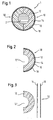
- FIG. 2 shows a schematic sectional view of a preferred embodiment of a semi-finished part 10 according to the invention for a heatable steering device.
- the semi-finished part 10 comprises a bow-shaped or arc-segment-shaped carrier 12, which in the present embodiment consists of layer-bonded and molded wood-based panels.
- the wood-based panels may be next to wood, for example, to fiber or MDF boards. These can be brought by compression molding in the form of a sheet segment and then provided by milling with the desired outer contour and a groove 12 'for receiving a steering wheel 2.
- the semi-finished part 10 comprises a veneer layer 18, which is preferably a noble veneer layer, although the present invention is not limited to a particular type of wood. It is inventively provided that the veneer layer 18 has a comparatively small thickness in the range of, for example, 0.5 to 2.0 mm. Furthermore, it is of course possible that the veneer layer has several layers of noble veneer.
- the veneer layer 18 is bonded to the carrier 12 by means of a bonding layer comprising a heater 14 and an adhesive layer 16.
- the heater 14 and In principle, the adhesive layer 16 may have any desired positioning between the carrier 12 and the veneer layer 18, wherein at least one of the two layers adjoins the at least one veneer layer 18. Likewise, the heater 14 and the adhesive layer 16 may penetrate each other, as will be explained in more detail below.
- the adhesive layer 16 preferably comprises a thermosetting adhesive which is based in particular on urea and / or melamine resin. These adhesives are inexpensive, easy to process, and provide a secure bond between the veneer layer 18 and the carrier 12. With regard to a specifically controllable and simple production of the semi-finished part according to the invention, it is further preferred that the adhesive layer 16 comprises a heat-activatable adhesive.
- the invention provides that the adhesive layer 16 contains thermally conductive particles, which preferably consist of a metallic material such as aluminum or the like. In this way, the thermal conductivity of the adhesive layer can be made even more homogeneous.
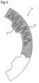
- the heater 14 of the present embodiment is shown schematically in Fig. 4 and is constituted by a mesh in which meander-shaped conductive fibers 14 'are provided as heating elements.
- the course and the arrangement of the conductive fibers 14 ' can in principle be adapted as desired to the desired heating of the semi-finished part.
- the shape of the heating device 14 or of the corresponding fabric can likewise be pressed against particular features of the semi-finished part or the steering device to be produced later, for example by providing extensions 14 "for the transition to steering wheel spokes, as shown in FIG. 4.
- the heater 14 Due to the fabric-like structure, the heater 14 has a high permeability for adhesive, in particular perpendicular to the plane in Fig. 4. This makes it possible that the adhesive layer and the heater 14 in the manufacture of the semi-finished part according to the invention form an intimate bond, so the heater 14 is largely embedded in the adhesive layer. This results in a particularly advantageous heating behavior of the semi-finished part according to the invention.
- FIG. 1 A schematic sectional view of a preferred embodiment of the heatable steering device 1 according to the invention is shown in FIG.
- the steering device 1 shown in Fig. 1 comprises two semi-finished parts 10, which are applied together on a steering rim 2 and connected to each other, for example glued. Furthermore, the steering device shown in Fig. 1 can be wrapped as a whole additionally with a lacquer layer to achieve a completely smooth surface and to close joints between adjacent semi-finished parts.
- the heatable steering apparatus 1 of the present invention is not limited to the embodiment shown in FIG. 1 formed by two semi-finished parts 10. Rather, it is within the scope of the present invention also possible to produce the steering device 1 without the use of precast elements by, for example, first the carrier 12 the turntable 2 is applied to then apply the remaining layers and mold to press.
- FIG. 3 shows a schematic, exploded sectional view of the embodiment shown in FIG.
- a bow-shaped or arc-segment-shaped carrier 12 made of wood or a wood-based material with the properties described at the outset is provided.
- the carrier 12 has a recess or groove 12 ', which makes it possible to apply the carrier 12 to a steering rim 2.
- a separate veneer layer 18 is provided, the shape of which may already approach the future outer contour of the semi-finished part 10, but which does not yet have to be in the final form.
- an adhesive layer 14 having the above-described properties is applied to a side surface of the substrate 12 to be provided with the veneer layer 18 and / or a side surface of the veneer layer 18 to face the substrate 12.
- the heater 16 may be placed on the adhesive layer 14 and thereby provisionally fixed to then bring the prepared parts into contact with each other and perform a compression molding of the carrier 12 and the (at least one) veneer layer 18.
- the respective side surfaces of the carrier 12 and the veneer layer 18 are bonded to each other via the adhesive layer 16, the adhesive layer 16 and / or the heater 14 being directly adjacent to the at least one veneer layer.
- the selection of the surfaces of the carrier 12 and the veneer layer 18, which are acted upon with adhesive, by the expert in be suitably adapted.
- the compression molding is preferably carried out with heat, in order to achieve a good moldability of the components and to activate an optionally heat-activatable adhesive.
- an optionally heat-activatable adhesive With regard to the activation of the adhesive, it is also possible to perform the compression molding in the high-frequency alternating field, resulting in a very uniform moisture distribution in the later semi-finished part.
- the at least one veneer layer 18 is applied to the carrier 12 and thereby brought into a new, permanent shape.
- pressures of at least 0.07 MPa have proven successful, although, depending on the toughness of the adhesive, the malleability of the veneer layer 18, etc., significantly higher pressures can also be used.
Landscapes
- Engineering & Computer Science (AREA)
- Chemical & Material Sciences (AREA)
- Combustion & Propulsion (AREA)
- Transportation (AREA)
- Mechanical Engineering (AREA)
- Steering Controls (AREA)
Claims (15)
- Dispositif de direction (1) pouvant être chauffé, en particulier pour des véhicules automobiles, comprenant :un support (12) en forme d'arc ou segment d'arc qui est appliqué sur une couronne de direction (2) ;au moins une couche de contreplacage (18), en particulier une couche de contreplacage de bois précieux, qui est reliée de façon fixe au support (12) ;une couche de liaison étant prévue entre le support (12) et la au moins une couche de contreplacage (1B), caractérisé en ce que le support est à base de bois ou d'un matériau de bois et la couche de liaison présente un dispositif de chauffage (14) et une couche de colle (16), le dispositif de chauffage (14) et/ou la couche de colle (16) étant directement contigus à la au moins une couche de contreplacage (18).
- Produit semi-fini (10) pour un dispositif de direction (1) pouvant être chauffé, en particulier pour des véhicules automobiles, comprenant :un support (12) en forme d'arc ou de segment d'arc, qui peut être appliqué sur une couronne de direction ;au moins une couche de contreplacage (18), en particulier une couche de contreplacage de bois précieux, qui est reliée de façon fixe au support (12) ;une couche de liaison étant prévue entre le support (12) et la au moins une couche de contreplacage (18), caractérisé en ce que le support est à base de bois ou d'un matériau de bois et la couche de liaison présente un dispositif de chauffage (14) et une couche de colle (16), le dispositif de chauffage (14) et/ou la couche de colle (16) étant directement contigus à la au moins une couche de contreplacage (18).
- Dispositif de direction ou produit semi-fini selon la revendication 1 ou 2, caractérisé en ce que la au moins une couche de contreplacage (18) est reliée au support (12) par compression de moulage.
- Dispositif de direction ou produit semi-fini selon l'une quelconque des revendications précédentes, caractérisé en ce que l'épaisseur de la au moins une couche de contreplacage (18) est au total au maximum de 2,0 mm, de préférence au maximum de 1,2 mm.
- Dispositif de direction ou produit semi-fini selon l'une quelconque des revendications précédentes, caractérisé en ce que la couche de colle (16) présente une colle duroplastique et/ou une colle pouvant être activée à la chaleur, en particulier à base d'urée et/ou de résine de mélamine.
- Dispositif de direction ou produit semi-fini selon l'une quelconque des revendications précédentes, caractérisé en ce que la couche de colle (16) présente des particules thermoconductibles, qui sont de préférence à base d'un matériau métallique, en particulier de l'aluminium.
- Dispositif de direction ou produit semi-fini selon l'une quelconque des revendications précédentes, caractérisé en ce que le dispositif de chauffage (14) est formé par un tissu ou un treillis qui présente des fibres (14') au moins en partie électroconductrices, des fibres ou similaires.
- Dispositif de direction ou produit semi-fini selon l'une quelconque des revendications précédentes, caractérisé en ce que le dispositif de chauffage (14) est perméable pour la colle au moins par endroits, en particulier perpendiculairement à un sens d'étirement à plat du dispositif de chauffage.
- Dispositif de direction ou produit semi-fini selon l'une quelconque des revendications précédentes, caractérisé en ce que le dispositif de chauffage (14) est enfoncé au moins partiellement dans la couche de colle (16).
- Dispositif de direction pouvant être chauffé, en particulier pour des véhicules automobiles, avec au moins deux produits semi-finis (10) selon l'une quelconque des revendications 2 à 9, qui sont appliquées sur une couronne de direction (2) commune et sont reliées entre elles.
- Procédé pour fabriquer un produit semi-fini (10) pour un dispositif de direction (1) pouvant être chauffé, en particulier pour des véhicules automobiles, comprenant les étapes suivantes :fabrication d'un support (12) en forme d'arc ou de segment d'arc à base de bois ou d'un matériau de bois, qui peut être appliqué sur une couronne de direction (2), et au moins d'une couche de contreplacage (18), en particulier une couche de contreplacage de bois précieux ;application d'une couche de colle (16) et d'un dispositif de chauffage (14) sur une première face latérale du support (12) et/ou une première face latérale de la au moins une couche de contreplacage (1B) ;compression par moulage du support (12) et de la au moins une couche de contreplacage (18), de telle sorte que les premières faces latérales respectives sont reliées entre elles au moyen de la au moins une couche de colle (16), la couche de colle (16) et/ou le dispositif de chauffage (14) étant directement contigus à la au moins une couche de contreplacage (18).
- Procédé selon la revendication 11, caractérisé en ce que la couche de colle (16) est appliquée sur la première face latérale du support (12) ou de la au moins une couche de contreplacage (18) et le dispositif de chauffage (14) est posé ensuite sur la couche de colle (16).
- Procédé selon la revendication 11 ou 12, caractérisé en ce que la compression par moulage s'effectue avec l'apport de chaleur et/ou dans la zone alternative à haute fréquence.
- Procédé selon l'une quelconque des revendications 11 à 13, caractérisé en ce que la au moins une couche de contreplacage (18) est amenée lors de la compression par moulage dans une nouvelle forme durable.
- Procédé selon l'une quelconque des revendications 11 à 14, caractérisé en ce que la au moins une couche de contreplacage (18) est alimentée lors de la compression par moulage au moins par endroits avec une pression d'au moins 0,07 MPa.
Priority Applications (1)
| Application Number | Priority Date | Filing Date | Title |
|---|---|---|---|
| PL04022476T PL1522483T3 (pl) | 2003-10-09 | 2004-09-22 | Ogrzewana kierownica, półfabrykat dla tej kierownicy i sposób wytwarzania półfabrykatu |
Applications Claiming Priority (2)
| Application Number | Priority Date | Filing Date | Title |
|---|---|---|---|
| DE10346942 | 2003-10-09 | ||
| DE10346942A DE10346942B3 (de) | 2003-10-09 | 2003-10-09 | Beheizbare Lenkvorrichtung, Halbfertigteil hierfür und Verfahren zur Herstellung eines Halbfertigteils |
Publications (3)
| Publication Number | Publication Date |
|---|---|
| EP1522483A2 EP1522483A2 (fr) | 2005-04-13 |
| EP1522483A3 EP1522483A3 (fr) | 2005-06-29 |
| EP1522483B1 true EP1522483B1 (fr) | 2006-11-08 |
Family
ID=34306339
Family Applications (1)
| Application Number | Title | Priority Date | Filing Date |
|---|---|---|---|
| EP04022476A Expired - Lifetime EP1522483B1 (fr) | 2003-10-09 | 2004-09-22 | Dispositif de direction chauffable, produit semi-fini et procédé de fabrication d'un produit semi-fini |
Country Status (3)
| Country | Link |
|---|---|
| EP (1) | EP1522483B1 (fr) |
| DE (2) | DE10346942B3 (fr) |
| PL (1) | PL1522483T3 (fr) |
Families Citing this family (5)
| Publication number | Priority date | Publication date | Assignee | Title |
|---|---|---|---|---|
| DE102004027008A1 (de) * | 2004-05-28 | 2005-12-29 | Takata-Petri Ag | Beheizbares Furnierelement für Kfz-Lenkräder und Verfahren zur Herstellung eines solchen Furnierelementes |
| DE102012023996A1 (de) * | 2012-09-28 | 2014-06-12 | W.E.T. Automotive Systems Ag | Temperiereinrichtung für Griffe, insbesondere von Lenkeinrichtungen |
| DE102012220288A1 (de) | 2012-11-07 | 2014-06-12 | Bayerische Motoren Werke Aktiengesellschaft | Fahrzeug-Lenkrad aus faserverstärktem Kunststoff |
| DE102015218424A1 (de) * | 2015-09-24 | 2017-03-30 | Volkswagen Aktiengesellschaft | Verfahren zum Herstellen eines verkleideten Lenkrads für ein Fahrzeug sowie mit dem Verfahren herstellbares Lenkrad |
| DE102018222551A1 (de) * | 2018-12-20 | 2020-06-25 | Joyson Safety Systems Germany Gmbh | Lenkrad für ein Kraftfahrzeug und Verfahren zum Herstellen eines Lenkrads |
Family Cites Families (9)
| Publication number | Priority date | Publication date | Assignee | Title |
|---|---|---|---|---|
| JPS5981252A (ja) * | 1982-11-02 | 1984-05-10 | Nissan Motor Co Ltd | リム部に発熱体を有するステアリングホイ−ル |
| DE3906576C1 (fr) * | 1989-03-02 | 1990-06-13 | Michael 8075 Vohburg De Scheuerer | |
| DE19528788C1 (de) * | 1995-08-04 | 1996-08-08 | Daimler Benz Ag | Verfahren zum Herstellen eines Lenkrades für Fahrzeuge mit einer Auflage aus einem Naturprodukt |
| US6038770A (en) * | 1997-02-25 | 2000-03-21 | Rainer Carrier | Process for the production of wood-veneer steering wheel |
| IT1303558B1 (it) * | 1998-09-03 | 2000-11-14 | Cavalli S R L | Procedimento per la realizzazione di volanti per veicoli, inparticolare volanti rivestiti in materiale pregiato, e volanti |
| DE29902044U1 (de) * | 1999-02-05 | 1999-04-08 | TRW Automotive Safety Systems GmbH, 63743 Aschaffenburg | Heizbares Holzlenkrad |
| DE19910132C1 (de) * | 1999-03-01 | 2000-03-16 | Petri Ag | Beheizbares Lenkrad |
| DE60113275T2 (de) * | 2000-07-22 | 2006-06-14 | Key Safety Systems Inc | Beheiztes lenkrad |
| WO2002080441A1 (fr) | 2001-04-02 | 2002-10-10 | Ueli Maurer | Declaration numerique, procede pour etablir une declaration numerique et produit logiciel pour mettre ledit procede en oeuvre |
-
2003
- 2003-10-09 DE DE10346942A patent/DE10346942B3/de not_active Expired - Fee Related
-
2004
- 2004-09-22 EP EP04022476A patent/EP1522483B1/fr not_active Expired - Lifetime
- 2004-09-22 DE DE502004001943T patent/DE502004001943D1/de not_active Expired - Lifetime
- 2004-09-22 PL PL04022476T patent/PL1522483T3/pl unknown
Also Published As
| Publication number | Publication date |
|---|---|
| EP1522483A2 (fr) | 2005-04-13 |
| DE10346942B3 (de) | 2005-06-30 |
| EP1522483A3 (fr) | 2005-06-29 |
| PL1522483T3 (pl) | 2007-03-30 |
| DE502004001943D1 (de) | 2006-12-21 |
Similar Documents
| Publication | Publication Date | Title |
|---|---|---|
| DE60319336T2 (de) | Lenkrad mit thermoplastischen Verbundmaterialien | |
| EP3037247B1 (fr) | Procédé de fabrication d'un élément sandwich | |
| DE69300586T2 (de) | Verfahren zur Herstellung eines Skis. | |
| DE69909199T2 (de) | Verfahren zum Herstellen von Kraftfahrzeuglenkrädern, insbesondere Lenkräder mit einer Hülle aus hochwertigem Material, und durch ein solches Verfahren hergestellte Lenkräder | |
| EP1138470B1 (fr) | Panneau intérieure de véhicule automobile comprenant un élément de chauffage intégré | |
| AT401352B (de) | Verfahren zum herstellen eines skis und nach diesem verfahren hergestellter ski | |
| DE4129959A1 (de) | Verfahren und fasermatte zur herstellung eines faserverstaerkten kunststoff-formteils sowie ein kunststoff-formteil | |
| EP3756888B1 (fr) | Procédé de fabrication d'une pièce décorative | |
| DE102019216528A1 (de) | Integrierte struktur aus verschiedenen arten von materialien und verfahren zur integration verschiedener arten von materialien | |
| EP2511095A1 (fr) | Laminage à froid avec radiation éléctromagnétique | |
| DE102015007885A1 (de) | Verfahren zum Herstellen eines Verbundbauteils für ein Fahrzeug, insbesondere einen Kraftwagen, sowie Verbundbauteil für ein Fahrzeug | |
| EP1839834B1 (fr) | Procédé de fabrication d'un élément moulé | |
| WO1999044811A1 (fr) | Composant sandwich en materiau composite renforce par fibres, et son procede de production | |
| DE102011079559A1 (de) | Fahrzeugsitz und verfahren zur herstellung desselben | |
| DE10346942B3 (de) | Beheizbare Lenkvorrichtung, Halbfertigteil hierfür und Verfahren zur Herstellung eines Halbfertigteils | |
| EP0370353A2 (fr) | Procédé de fabrication d'un laminat de postformage | |
| DE102005058614A1 (de) | Blende für einen beheizbaren Handgriff | |
| DE102004062646B4 (de) | Lenkraddekorschalen und Interieurzierelemente sowie Verfahren zu deren Herstellung | |
| DE19731903A1 (de) | Verfahren zur Herstellung eines Dachmoduls oder Schiebedaches für Fahrzeuge | |
| DE10321220B3 (de) | Verfahren zum Herstellen von Segment- oder Endlosbögen für Lenkräder sowie Lenkrad | |
| DE102006041787A1 (de) | Mehrschichtiges Innenausstattungsbauteil | |
| DE102012214752A1 (de) | Fahrzeuglenkrad | |
| EP2969459A1 (fr) | Pièce en mousse particulaire et son procédé de production | |
| EP0718097B1 (fr) | Procédé de fabrication d'un revêtement intérieur plat pour véhicule automobile et revêtement obtenu par ce procédé | |
| DE102021003857B3 (de) | Verfahren zur Herstellung eines Interieurbauteils für einen Innenraum eines Kraftwagens |
Legal Events
| Date | Code | Title | Description |
|---|---|---|---|
| PUAI | Public reference made under article 153(3) epc to a published international application that has entered the european phase |
Free format text: ORIGINAL CODE: 0009012 |
|
| AK | Designated contracting states |
Kind code of ref document: A2 Designated state(s): AT BE BG CH CY CZ DE DK EE ES FI FR GB GR HU IE IT LI LU MC NL PL PT RO SE SI SK TR |
|
| AX | Request for extension of the european patent |
Extension state: AL HR LT LV MK |
|
| PUAL | Search report despatched |
Free format text: ORIGINAL CODE: 0009013 |
|
| AK | Designated contracting states |
Kind code of ref document: A3 Designated state(s): AT BE BG CH CY CZ DE DK EE ES FI FR GB GR HU IE IT LI LU MC NL PL PT RO SE SI SK TR |
|
| AX | Request for extension of the european patent |
Extension state: AL HR LT LV MK |
|
| 17P | Request for examination filed |
Effective date: 20051117 |
|
| AKX | Designation fees paid |
Designated state(s): DE FR GB IT PL RO |
|
| GRAP | Despatch of communication of intention to grant a patent |
Free format text: ORIGINAL CODE: EPIDOSNIGR1 |
|
| GRAS | Grant fee paid |
Free format text: ORIGINAL CODE: EPIDOSNIGR3 |
|
| GRAA | (expected) grant |
Free format text: ORIGINAL CODE: 0009210 |
|
| AK | Designated contracting states |
Kind code of ref document: B1 Designated state(s): DE FR GB IT PL RO |
|
| REG | Reference to a national code |
Ref country code: GB Ref legal event code: FG4D Free format text: NOT ENGLISH |
|
| REG | Reference to a national code |
Ref country code: RO Ref legal event code: EPE |
|
| REF | Corresponds to: |
Ref document number: 502004001943 Country of ref document: DE Date of ref document: 20061221 Kind code of ref document: P |
|
| REG | Reference to a national code |
Ref country code: PL Ref legal event code: T3 |
|
| ET | Fr: translation filed | ||
| PLBE | No opposition filed within time limit |
Free format text: ORIGINAL CODE: 0009261 |
|
| STAA | Information on the status of an ep patent application or granted ep patent |
Free format text: STATUS: NO OPPOSITION FILED WITHIN TIME LIMIT |
|
| 26N | No opposition filed |
Effective date: 20070809 |
|
| PG25 | Lapsed in a contracting state [announced via postgrant information from national office to epo] |
Ref country code: IT Free format text: LAPSE BECAUSE OF NON-PAYMENT OF DUE FEES Effective date: 20080922 |
|
| PGRI | Patent reinstated in contracting state [announced from national office to epo] |
Ref country code: IT Effective date: 20110616 |
|
| PGFP | Annual fee paid to national office [announced via postgrant information from national office to epo] |
Ref country code: GB Payment date: 20110803 Year of fee payment: 8 Ref country code: RO Payment date: 20110919 Year of fee payment: 8 Ref country code: PL Payment date: 20110729 Year of fee payment: 8 Ref country code: FR Payment date: 20111005 Year of fee payment: 8 |
|
| PGFP | Annual fee paid to national office [announced via postgrant information from national office to epo] |
Ref country code: IT Payment date: 20110923 Year of fee payment: 8 |
|
| GBPC | Gb: european patent ceased through non-payment of renewal fee |
Effective date: 20120922 |
|
| REG | Reference to a national code |
Ref country code: FR Ref legal event code: ST Effective date: 20130531 |
|
| PG25 | Lapsed in a contracting state [announced via postgrant information from national office to epo] |
Ref country code: GB Free format text: LAPSE BECAUSE OF NON-PAYMENT OF DUE FEES Effective date: 20120922 |
|
| PG25 | Lapsed in a contracting state [announced via postgrant information from national office to epo] |
Ref country code: RO Free format text: LAPSE BECAUSE OF NON-PAYMENT OF DUE FEES Effective date: 20120922 Ref country code: IT Free format text: LAPSE BECAUSE OF NON-PAYMENT OF DUE FEES Effective date: 20120922 Ref country code: FR Free format text: LAPSE BECAUSE OF NON-PAYMENT OF DUE FEES Effective date: 20121001 |
|
| PGFP | Annual fee paid to national office [announced via postgrant information from national office to epo] |
Ref country code: DE Payment date: 20130923 Year of fee payment: 10 |
|
| PG25 | Lapsed in a contracting state [announced via postgrant information from national office to epo] |
Ref country code: PL Free format text: LAPSE BECAUSE OF NON-PAYMENT OF DUE FEES Effective date: 20120922 |
|
| REG | Reference to a national code |
Ref country code: PL Ref legal event code: LAPE |
|
| REG | Reference to a national code |
Ref country code: DE Ref legal event code: R119 Ref document number: 502004001943 Country of ref document: DE |
|
| PG25 | Lapsed in a contracting state [announced via postgrant information from national office to epo] |
Ref country code: DE Free format text: LAPSE BECAUSE OF NON-PAYMENT OF DUE FEES Effective date: 20150401 |