EP1522493A1 - Dispositif de palier élastomérique - Google Patents
Dispositif de palier élastomérique Download PDFInfo
- Publication number
- EP1522493A1 EP1522493A1 EP04077737A EP04077737A EP1522493A1 EP 1522493 A1 EP1522493 A1 EP 1522493A1 EP 04077737 A EP04077737 A EP 04077737A EP 04077737 A EP04077737 A EP 04077737A EP 1522493 A1 EP1522493 A1 EP 1522493A1
- Authority
- EP
- European Patent Office
- Prior art keywords
- elastomeric bearing
- elastomeric
- bearing element
- internal
- bearing system
- Prior art date
- Legal status (The legal status is an assumption and is not a legal conclusion. Google has not performed a legal analysis and makes no representation as to the accuracy of the status listed.)
- Granted
Links
- 230000033001 locomotion Effects 0.000 claims abstract description 16
- 230000002459 sustained effect Effects 0.000 claims description 14
- 230000036316 preload Effects 0.000 claims description 10
- 238000000034 method Methods 0.000 claims description 8
- 229920001967 Metal rubber Polymers 0.000 claims description 5
- 239000002648 laminated material Substances 0.000 claims description 4
- 229920001971 elastomer Polymers 0.000 description 7
- 239000002184 metal Substances 0.000 description 4
- 230000006835 compression Effects 0.000 description 3
- 238000007906 compression Methods 0.000 description 3
- 230000000694 effects Effects 0.000 description 3
- 239000000806 elastomer Substances 0.000 description 3
- 229910000831 Steel Inorganic materials 0.000 description 2
- 238000000429 assembly Methods 0.000 description 2
- 238000012423 maintenance Methods 0.000 description 2
- 239000010959 steel Substances 0.000 description 2
- RZVHIXYEVGDQDX-UHFFFAOYSA-N 9,10-anthraquinone Chemical compound C1=CC=C2C(=O)C3=CC=CC=C3C(=O)C2=C1 RZVHIXYEVGDQDX-UHFFFAOYSA-N 0.000 description 1
- 229920000271 Kevlar® Polymers 0.000 description 1
- 230000000712 assembly Effects 0.000 description 1
- 239000000919 ceramic Substances 0.000 description 1
- 239000002131 composite material Substances 0.000 description 1
- 230000001419 dependent effect Effects 0.000 description 1
- 239000000463 material Substances 0.000 description 1
- 230000007246 mechanism Effects 0.000 description 1
- 230000003534 oscillatory effect Effects 0.000 description 1
- 230000021715 photosynthesis, light harvesting Effects 0.000 description 1
- 229920000642 polymer Polymers 0.000 description 1
Images

Classifications
-
- F—MECHANICAL ENGINEERING; LIGHTING; HEATING; WEAPONS; BLASTING
- F16—ENGINEERING ELEMENTS AND UNITS; GENERAL MEASURES FOR PRODUCING AND MAINTAINING EFFECTIVE FUNCTIONING OF MACHINES OR INSTALLATIONS; THERMAL INSULATION IN GENERAL
- F16F—SPRINGS; SHOCK-ABSORBERS; MEANS FOR DAMPING VIBRATION
- F16F3/00—Spring units consisting of several springs, e.g. for obtaining a desired spring characteristic
- F16F3/08—Spring units consisting of several springs, e.g. for obtaining a desired spring characteristic with springs made of a material having high internal friction, e.g. rubber
- F16F3/087—Units comprising several springs made of plastics or the like material
- F16F3/0873—Units comprising several springs made of plastics or the like material of the same material or the material not being specified
-
- B—PERFORMING OPERATIONS; TRANSPORTING
- B64—AIRCRAFT; AVIATION; COSMONAUTICS
- B64C—AEROPLANES; HELICOPTERS
- B64C27/00—Rotorcraft; Rotors peculiar thereto
- B64C27/32—Rotors
- B64C27/35—Rotors having elastomeric joints
-
- F—MECHANICAL ENGINEERING; LIGHTING; HEATING; WEAPONS; BLASTING
- F16—ENGINEERING ELEMENTS AND UNITS; GENERAL MEASURES FOR PRODUCING AND MAINTAINING EFFECTIVE FUNCTIONING OF MACHINES OR INSTALLATIONS; THERMAL INSULATION IN GENERAL
- F16F—SPRINGS; SHOCK-ABSORBERS; MEANS FOR DAMPING VIBRATION
- F16F1/00—Springs
- F16F1/36—Springs made of rubber or other material having high internal friction, e.g. thermoplastic elastomers
- F16F1/38—Springs made of rubber or other material having high internal friction, e.g. thermoplastic elastomers with a sleeve of elastic material between a rigid outer sleeve and a rigid inner sleeve or pin, i.e. bushing-type
- F16F1/393—Springs made of rubber or other material having high internal friction, e.g. thermoplastic elastomers with a sleeve of elastic material between a rigid outer sleeve and a rigid inner sleeve or pin, i.e. bushing-type with spherical or conical sleeves
- F16F1/3935—Conical sleeves
Definitions
- This invention relates generally to elastomeric bearings and more specifically to a bearing system capable of sustaining a high compressive load, thus allowing a pivot movement around an axis substantially perpendicular to said load.
- the invention can be applied, in particular, in a helicopter rotorhead to provide the blades with the flapping degree of freedom.
- a key component of a helicopter is the main rotor hub. It provides attachment of the main rotor blades during operation. Rotational power is delivered to the main rotor hub to provide rotational velocity to the blades in order to create aerodynamic lift.
- the main rotor hub must allow for rotational motion of the blades in the vertical (flap), horizontal (lead-lag), and axial (pitch) directions near the blade root attachment with the hub to accommodate flight control and dynamic stability regulation.
- Main rotor hub systems that accommodate these motions with discrete hinge mechanisms are referred to as fully articulated hubs.
- elastomeric bearings have become an industry standard for accommodating either lead-lag, or pitch, or flapping, or combined motions in articulated hub systems. These bearings are composed of a metal-elastomer laminated material that allows for shear compliance within the elastomer, and for rotational (e.g. flapping) freedom while reacting radial centrifugal force in compression. Such bearings reduce the mechanical complexity of the rotor head, are essentially maintenance-free, wear progressively and can be easily inspected in order to be replaced before failure.
- Elastomeric conical bearings known, for example, from US. Pat. No. 4,435,097, are used in bearing systems for helicopter rotor systems to accommodate rotor motion.
- the bearing systems are axially preloaded to prevent the conical bearing elements from experiencing an excessive resultant tensile stress within the rubber layers.
- US. Pat. No. 6,413,048 discloses a rotor hub using a pair of simple conical bearing for each rotor blade.
- Such a bearing has a very high radial stiffness and resistance to compressive radial loads, and at the same time it can easily accommodates a pivot movement around its axis, as it is desired in the present application.
- the rotor hub must provide the axial compression preload reaction, which induces a significant stress in its central body. When the bearing is heated, due to operational temperature increase and internal energy dissipation, the stress transmitted to the hub increases further, and this can be critical for the structure.
- the present invention addresses the problem of providing a low maintenance elastomeric bearing system with a long operational life, thus overcoming the drawbacks of the above-described prior art.
- An object of this invention is to provide an elastomeric bearing system comprising: a first and a second elastomeric bearing element fixed at the opposite ends of a tie bar, wherein said first elastomeric bearing element comprises a rigid external housing having an internal truncated-tapered surface, a rigid internal housing having an external truncated-tapered surface, and a resilient body between said internal and external truncated-tapered surfaces; and said second elastomeric bearing element is constituted by a chevron sub-assembly, comprising two opposed tapered elastomeric bearing elements, each having an individual internal housing and an individual resilient body, and having an external housing with a double-taper internal surface, the internal housings being connected one another by fastening elements.
- truncated-tapered refers primarily to truncated-conical surfaces, but also, more generally, to surfaces having a curbed longitudinal cross-section and a shape substantially reminding that of a truncated cone. Such surfaces can be, for example, portions of spherical (or ellipsoidal) surfaces comprised between two parallels of the same hemisphere.
- the "tapered surfaces” need not have rotational symmetry.
- each of said first and second elastomeric bearing element is fitted within a rigid support which can be, for example, the hub of a rotor.
- the resilient bodies of said first and a second elastomeric bearing elements are constituted by a metal-elastomer laminated material.
- the shear elasticity of said first and second elastomeric bearing elements allows a pivot movement of said tie bar around its own axis.
- a typical requirement in helicopter application is that the amplitude of said pivot movement can attain a peak-to-peak amplitude of up to 30°.
- said first and second elastomeric bearing elements are advantageously compressed by an axial preload, whose magnitude, in a preferred embodiment of the invention, is 3.800 kgf or higher, and is advantageously comprised between 3.800 kgf and 6.800 kgf.
- the load induced by thermal expansion of the elastomeric bodies of said second elastomeric bearing element is internally compensated by said fastening elements connecting said internal housings one another.
- Another object of the invention is a method for mounting an elastomeric bearing system comprising:
- the radial load sustained by said first elastomeric bearing element is comprised between 27.000 kgf and 50.000 kgf.
- the radial load sustained by said second elastomeric bearing element is comprised between 40% and 60% of the load sustained by said first elastomeric bearing element.
- An axial force can also be applied to the tie bar and transmitted to said elastomeric bearing elements.
- the magnitude of said axial force is typically comprised between 1.300 kgf and 4.100 kgf.
- Another object of the invention is a rotor hub assembly comprising: a hub center body; and a plurality of radially extending shafts, each of them relying one rotor blade to the hub center body; wherein each of those said radially extending shafts is connected to said hub center body by an elastomeric bearing system as previously described, mounted with said first elastomeric bearing element on the lead side and said second elastomeric bearing element on the lag side, whereby the radial load sustained by said first elastomeric bearing element is greater than that sustained by said second elastomeric bearing element.
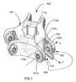
- Figure 1 depicts an articulated hub assembly 100 that includes a plurality of rotor assemblies 103 radially attached to a hub center body 101; for a better clarity of the figure, only one rotor assembly is represented here.
- the articulated hub assembly 100 is designed to allow and to control the blades flap motion.
- Other bearings or bushings (not shown) are optionally used to allow pitch and lead-lag motion.
- the rotor assembly 103 includes a tie bar 105 carrying a radially extending shaft 106, which relies one rotor blade to the hub center body 101, usually through additional mechanical elements, such as the aforementioned bearings or bushings (not shown).
- the tie bar 105 is a substantially cylindrical shaped element having a pair of radially opposed journals 107a, b at both ends; each journal is designed to be fixed to the bearing mounting 109.
- the bearing mounting 109 includes two pair of radially extending bearing flanges 111a, b each containing an elastomeric bearing element 113a,b.
- the bearing elements have to sustain the centrifugal load in the Y direction, produced by the rotation of the rotor, allowing at the same time pivot movement around the X axis (flapping).
- bearing mounting refers to the two bearing flanges 111a,b together with the corresponding bearing elements 113a,b
- bearing system refers to the two bearing elements 113a,b with the tie bar 105.
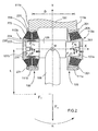
- FIG. 2 shows a section in the XY plane of the bearing mounting 109 of figure 1, realized according to the teaching of the present invention.
- bearing mounting 109 has an asymmetric structure: the lead-side bearing element 113a is of the simple conical type, while the lag-side bearing element 113b has a chevron design (arrow R indicates the rotation direction of the rotor).
- arrow R indicates the rotation direction of the rotor.
- the centrifugal force F C is, indeed, symmetrical, but aerodynamics laws and rotor design induce a torque M on the bearing mounting.
- the bearings must also sustain an axial load due to the air resistance to the rotation of the blades (F T ): this prevents the use of cylindrical bearings, which would not have a sufficient axial stiffness.
- the axial load on the lead-side (simple conical) bearing element is referenced in figure 2 as F Ta and that on the lag-side (chevron) bearing element as F Tb ; these loads can, in general, be different, depending on the axial stiffness of the bearing elements, and their sum is equal to F T .
- the overall compressive load is unevenly shared between two bearing elements: on the lag side it is less than it would have been expected if only the centrifugal force had been taken into account, as in the conventional design procedure.
- This allows the use, on that side, of a chevron bearing element, which reduces the stress on the rotor hub 101.
- the simple conical bearing 113a is constituted by a rigid external housing 201 having an internal conical surface and secured to the bearing flange 111a, a rigid internal housing 203 having an external conical surface and fixed to the tie bar journal 107a, and a resilient body 205 between said internal and external conical surfaces. While the housings 201 and 203 are typically made of metal, e.g. steel, the resilient body is a laminated composite, constituted by a succession of conical layers of steel (or another metal) and rubber.
- the axial compressive preload (oriented along the positive direction of the X axis) is transmitted to the resilient body 205 through the flanges 111a,b and the tie bar 105. Thermal expansion of rubber induces a supplementary load that adds to the preloads and tends to bring the flanges 111a and 111b together.
- the chevron sub-assembly 113b is composed by two conical elements disposed back-to-back with their minor basis facing each other, (the opposite arrangement is also possible), each having an individual internal housing (223 and 224) and an individual elastomeric body (225 and 226), and having an external housing 221 with a double-cone internal surface.
- the internal housings are connected one another by bolts 230, which can be used to apply an internal preload to the elastomeric bodies.
- the preload is entirely internal, but in the present setup the chevron sub-assembly 113b is at least partially preloaded through the flanges 111a-b and the tie bar 105.
- the thermally induced load is internally compensated for by bolts 230 and not transmitted to the hub 101.
- thermal expansion of the elastomeric body of the conical bearing element 113a induces a load F Tha that is transmitted to the tie bar 105, which is put in traction, and to the flange 111a.
- the chevron bearing sub-assembly generates a thermal load F Thb that is approximately 40% lower than F Tha , because of the lower stiffness of the chevron bearing compared to the simple conical one, but is internally compensated for.
- the load F Tha is transmitted through the tie bar 105 to the flange 111b: in conclusion, the force acting on each flange, and trying to bring them together, is equal to F Tha and is only due to the contribution of the conical bearing element 113a.
- the simple conical bearing element 113a could also have been mounted with the opposite orientation (with the minor basis of the internal casing directed outwardly). In this case, the preload and the thermal load would have been reversed.
- the elastomeric bearing elements 113a and 113b are designed according to procedures known in the art in order to meet the requirements on radial, axial and torsion stiffness, on the life duration and on the maximal thermal load injected in the hub 101 by the conical bearing.
- the two elastomeric bearings although of different types, must have stiffness properties near to each other.
- the bearing system of the invention can be adapted to different rotor hub designs and to other application even outside the field of helicopters such as, for example, wind power generators. More generally, the teaching of the present invention can be advantageously applied in any mechanical structure, whenever it is necessary to provide a bearing system capable of sustaining a high compressive load unevenly shared between two bearing elements, thus allowing a pivot movement around an axis approximately perpendicular to said load, and particularly when thermal expansion is of concern.
- bearings constituted by metal-elastomer laminated have been considered. It is to be intended, however, that the metal can be replaced by any other suitable stiff material, such a polymer (Kevlar ®) or a ceramic. The same thing is true for the internal and external housing, the tie bar and the flanges.
- the bearings have been described as "conical” in order to withstand an axial load, but this should not be interpreted in a strict geometrical sense. What is important is that the metal-elastomer layers are neither parallel to the tie bar (cylindrical bearings, having a low axial stiffness), neither perpendicular to it (in which case the bearings could not sustain a radial load). Bearings whose layers have a curbed longitudinal cross section, in particular constituting portions of spherical surfaces, still reminding the shape of a truncated cone, are encompassed by the general term "tapered bearings".
- the bearings can have rotation symmetry, as in the example discussed above: this means that the stiffness is the same in all the radial directions. However, in some applications, it might be useful to introduce an anisotropic behavior.
- the envelope of a bearing can be constituted by the union of two 120° portions of a cylindrical surface: the result is a radial direction-dependent stiffness.
Landscapes
- Engineering & Computer Science (AREA)
- General Engineering & Computer Science (AREA)
- Mechanical Engineering (AREA)
- Aviation & Aerospace Engineering (AREA)
- Support Of The Bearing (AREA)
- Springs (AREA)
- Glass Compositions (AREA)
Applications Claiming Priority (2)
| Application Number | Priority Date | Filing Date | Title |
|---|---|---|---|
| US10/682,856 US6971853B2 (en) | 2003-10-14 | 2003-10-14 | Elastomeric bearing system |
| US682856 | 2003-10-14 |
Publications (2)
| Publication Number | Publication Date |
|---|---|
| EP1522493A1 true EP1522493A1 (fr) | 2005-04-13 |
| EP1522493B1 EP1522493B1 (fr) | 2007-08-29 |
Family
ID=34314144
Family Applications (1)
| Application Number | Title | Priority Date | Filing Date |
|---|---|---|---|
| EP04077737A Expired - Lifetime EP1522493B1 (fr) | 2003-10-14 | 2004-10-08 | Dispositif de palier élastomérique |
Country Status (4)
| Country | Link |
|---|---|
| US (1) | US6971853B2 (fr) |
| EP (1) | EP1522493B1 (fr) |
| AT (1) | ATE371580T1 (fr) |
| DE (1) | DE602004008548T2 (fr) |
Cited By (1)
| Publication number | Priority date | Publication date | Assignee | Title |
|---|---|---|---|---|
| WO2011017344A3 (fr) * | 2009-08-04 | 2011-09-15 | Itt Manufacturing Enterprises, Inc. | Isolateur pouvant être utilisé pour un montage en ligne avec une entretoise |
Families Citing this family (8)
| Publication number | Priority date | Publication date | Assignee | Title |
|---|---|---|---|---|
| US8511997B2 (en) * | 2007-12-19 | 2013-08-20 | Sikorsky Aircraft Corporation | Uniform fatigue life spherical elastomeric bearing |
| US20090159382A1 (en) * | 2007-12-21 | 2009-06-25 | Louis Chemouni | Rotary damper |
| WO2011106050A2 (fr) * | 2009-11-23 | 2011-09-01 | Lord Corporation | Palier élastomère stratifié à haute capacité d'aéronef à voilure tournante pour aéronef à voilure tournante |
| US10214284B2 (en) | 2013-09-30 | 2019-02-26 | Sikorsky Aircraft Corporation | Pitch bearing |
| US9873507B2 (en) * | 2014-02-26 | 2018-01-23 | Bell Helicopter Textron Inc. | Rotorcraft elastomeric bearing assembly |
| US9347487B2 (en) * | 2014-05-30 | 2016-05-24 | Bell Helicopter Textron Inc. | Rotorcraft bearing with rotation slip joint |
| CN105003577A (zh) | 2015-06-15 | 2015-10-28 | 株洲时代新材料科技股份有限公司 | 双向减振器 |
| US11618557B2 (en) * | 2020-08-27 | 2023-04-04 | Textron Innovations Inc. | Centrifugal force bearing with piezo clutch |
Citations (5)
| Publication number | Priority date | Publication date | Assignee | Title |
|---|---|---|---|---|
| US4395143A (en) * | 1978-08-21 | 1983-07-26 | Thiokol Corporation | Annular, flexible bearings for radial loads |
| US4859148A (en) * | 1988-02-26 | 1989-08-22 | United Technologies Corporation | Preloaded tunable elastomeric flapping hinge bearing and method of preloading |
| DE4128488A1 (de) * | 1991-08-28 | 1993-03-04 | Joern Gmbh | Doppelquerlenker-vorderachsfuehrung |
| US6413048B1 (en) * | 2000-09-29 | 2002-07-02 | The Boeing Company | Elastomeric bearing |
| US20030068104A1 (en) * | 2001-10-10 | 2003-04-10 | Loftus Robert T. | Opposing conical preloaded elastomeric bearing assembly |
Family Cites Families (2)
| Publication number | Priority date | Publication date | Assignee | Title |
|---|---|---|---|---|
| US4028002A (en) * | 1976-03-01 | 1977-06-07 | Lord Corporation | Rotor blade retention system |
| US4365936A (en) * | 1979-12-06 | 1982-12-28 | Chicago Rawhide Manufacturing Company | Laminated elastomeric bearing unit |
-
2003
- 2003-10-14 US US10/682,856 patent/US6971853B2/en not_active Expired - Lifetime
-
2004
- 2004-10-08 EP EP04077737A patent/EP1522493B1/fr not_active Expired - Lifetime
- 2004-10-08 DE DE602004008548T patent/DE602004008548T2/de not_active Expired - Lifetime
- 2004-10-08 AT AT04077737T patent/ATE371580T1/de not_active IP Right Cessation
Patent Citations (5)
| Publication number | Priority date | Publication date | Assignee | Title |
|---|---|---|---|---|
| US4395143A (en) * | 1978-08-21 | 1983-07-26 | Thiokol Corporation | Annular, flexible bearings for radial loads |
| US4859148A (en) * | 1988-02-26 | 1989-08-22 | United Technologies Corporation | Preloaded tunable elastomeric flapping hinge bearing and method of preloading |
| DE4128488A1 (de) * | 1991-08-28 | 1993-03-04 | Joern Gmbh | Doppelquerlenker-vorderachsfuehrung |
| US6413048B1 (en) * | 2000-09-29 | 2002-07-02 | The Boeing Company | Elastomeric bearing |
| US20030068104A1 (en) * | 2001-10-10 | 2003-04-10 | Loftus Robert T. | Opposing conical preloaded elastomeric bearing assembly |
Cited By (1)
| Publication number | Priority date | Publication date | Assignee | Title |
|---|---|---|---|---|
| WO2011017344A3 (fr) * | 2009-08-04 | 2011-09-15 | Itt Manufacturing Enterprises, Inc. | Isolateur pouvant être utilisé pour un montage en ligne avec une entretoise |
Also Published As
| Publication number | Publication date |
|---|---|
| EP1522493B1 (fr) | 2007-08-29 |
| US6971853B2 (en) | 2005-12-06 |
| ATE371580T1 (de) | 2007-09-15 |
| DE602004008548D1 (de) | 2007-10-11 |
| DE602004008548T2 (de) | 2008-05-21 |
| US20050079055A1 (en) | 2005-04-14 |
Similar Documents
| Publication | Publication Date | Title |
|---|---|---|
| US10532809B2 (en) | Rotor hub bearing system | |
| EP4001107B1 (fr) | Palier basculant élastique léger pour rotor et aéronef comportant un tel palier | |
| US9878782B2 (en) | Stiff-in-plane rotor configuration | |
| US7047596B2 (en) | Structural bushing application for highly loaded composites lugs | |
| US4804352A (en) | Link-type rotary coupling | |
| US5120195A (en) | Clevis joint capable of accommodating substantial pivotal motion between its joined members and loading along its axis | |
| CA2036598A1 (fr) | Rotor d'helicoptere a noyeu rigide muni d'un amortisseur de vibrations ameliore entre la barre de torsion et la pale | |
| US11066157B2 (en) | Constant-velocity joint link with reduced axial stiffness | |
| EP1522493B1 (fr) | Dispositif de palier élastomérique | |
| KR101619996B1 (ko) | 회전익 항공기의 로터 시스템 | |
| US5562416A (en) | Helicopter rotor blade mounting assembly | |
| EP2234881A2 (fr) | Palier spherique en elastomere presentant une resistance a la fatigue uniforme | |
| US10759529B2 (en) | Rotor blade coupling device of a rotor head for a rotorcraft | |
| EP3739227B1 (fr) | Palier pour une transmission d'éolienne ayant un support en élastomère | |
| US5499903A (en) | Snubber bearing mounting assembly for bearingless rotors | |
| US5083725A (en) | Elastomeric swashplate configuration for helicopters | |
| CN113226924B (zh) | 飞行器 | |
| MX2009001731A (es) | Acoplamiento de par de torsion para nave aerea de ala rotativa con cojinetes de almohadilla. | |
| US11111012B2 (en) | Hub with integral elastomeric bearing | |
| EP0491647B1 (fr) | Palier amortisseur avec couches élastomères combinées | |
| EP4253781A1 (fr) | Ensemble de couplage | |
| WO1995002131A1 (fr) | Amortisseur tubulaire segmente a elastomere |
Legal Events
| Date | Code | Title | Description |
|---|---|---|---|
| PUAI | Public reference made under article 153(3) epc to a published international application that has entered the european phase |
Free format text: ORIGINAL CODE: 0009012 |
|
| AK | Designated contracting states |
Kind code of ref document: A1 Designated state(s): AT BE BG CH CY CZ DE DK EE ES FI FR GB GR HU IE IT LI LU MC NL PL PT RO SE SI SK TR |
|
| AX | Request for extension of the european patent |
Extension state: AL HR LT LV MK |
|
| 17P | Request for examination filed |
Effective date: 20050930 |
|
| AKX | Designation fees paid |
Designated state(s): AT BE BG CH CY CZ DE DK EE ES FI FR GB GR HU IE IT LI LU MC NL PL PT RO SE SI SK TR |
|
| GRAP | Despatch of communication of intention to grant a patent |
Free format text: ORIGINAL CODE: EPIDOSNIGR1 |
|
| GRAS | Grant fee paid |
Free format text: ORIGINAL CODE: EPIDOSNIGR3 |
|
| GRAA | (expected) grant |
Free format text: ORIGINAL CODE: 0009210 |
|
| AK | Designated contracting states |
Kind code of ref document: B1 Designated state(s): AT BE BG CH CY CZ DE DK EE ES FI FR GB GR HU IE IT LI LU MC NL PL PT RO SE SI SK TR |
|
| REG | Reference to a national code |
Ref country code: GB Ref legal event code: FG4D |
|
| REG | Reference to a national code |
Ref country code: CH Ref legal event code: EP |
|
| REG | Reference to a national code |
Ref country code: IE Ref legal event code: FG4D |
|
| REF | Corresponds to: |
Ref document number: 602004008548 Country of ref document: DE Date of ref document: 20071011 Kind code of ref document: P |
|
| PG25 | Lapsed in a contracting state [announced via postgrant information from national office to epo] |
Ref country code: NL Free format text: LAPSE BECAUSE OF FAILURE TO SUBMIT A TRANSLATION OF THE DESCRIPTION OR TO PAY THE FEE WITHIN THE PRESCRIBED TIME-LIMIT Effective date: 20070829 Ref country code: ES Free format text: LAPSE BECAUSE OF FAILURE TO SUBMIT A TRANSLATION OF THE DESCRIPTION OR TO PAY THE FEE WITHIN THE PRESCRIBED TIME-LIMIT Effective date: 20071210 Ref country code: FI Free format text: LAPSE BECAUSE OF FAILURE TO SUBMIT A TRANSLATION OF THE DESCRIPTION OR TO PAY THE FEE WITHIN THE PRESCRIBED TIME-LIMIT Effective date: 20070829 |
|
| NLV1 | Nl: lapsed or annulled due to failure to fulfill the requirements of art. 29p and 29m of the patents act | ||
| PG25 | Lapsed in a contracting state [announced via postgrant information from national office to epo] |
Ref country code: PL Free format text: LAPSE BECAUSE OF FAILURE TO SUBMIT A TRANSLATION OF THE DESCRIPTION OR TO PAY THE FEE WITHIN THE PRESCRIBED TIME-LIMIT Effective date: 20070829 Ref country code: LI Free format text: LAPSE BECAUSE OF FAILURE TO SUBMIT A TRANSLATION OF THE DESCRIPTION OR TO PAY THE FEE WITHIN THE PRESCRIBED TIME-LIMIT Effective date: 20070829 Ref country code: CH Free format text: LAPSE BECAUSE OF FAILURE TO SUBMIT A TRANSLATION OF THE DESCRIPTION OR TO PAY THE FEE WITHIN THE PRESCRIBED TIME-LIMIT Effective date: 20070829 Ref country code: AT Free format text: LAPSE BECAUSE OF FAILURE TO SUBMIT A TRANSLATION OF THE DESCRIPTION OR TO PAY THE FEE WITHIN THE PRESCRIBED TIME-LIMIT Effective date: 20070829 |
|
| REG | Reference to a national code |
Ref country code: CH Ref legal event code: PL |
|
| PG25 | Lapsed in a contracting state [announced via postgrant information from national office to epo] |
Ref country code: BE Free format text: LAPSE BECAUSE OF FAILURE TO SUBMIT A TRANSLATION OF THE DESCRIPTION OR TO PAY THE FEE WITHIN THE PRESCRIBED TIME-LIMIT Effective date: 20070829 |
|
| EN | Fr: translation not filed | ||
| PG25 | Lapsed in a contracting state [announced via postgrant information from national office to epo] |
Ref country code: DK Free format text: LAPSE BECAUSE OF FAILURE TO SUBMIT A TRANSLATION OF THE DESCRIPTION OR TO PAY THE FEE WITHIN THE PRESCRIBED TIME-LIMIT Effective date: 20070829 Ref country code: GR Free format text: LAPSE BECAUSE OF FAILURE TO SUBMIT A TRANSLATION OF THE DESCRIPTION OR TO PAY THE FEE WITHIN THE PRESCRIBED TIME-LIMIT Effective date: 20071130 |
|
| ET | Fr: translation filed | ||
| REG | Reference to a national code |
Ref country code: FR Ref legal event code: EERR Free format text: CORRECTION DE BOPI 08/17 - BREVETS EUROPEENS DONT LA TRADUCTION N A PAS ETE REMISE A L INPI. IL Y A LIEU DE SUPPRIMER : LA MENTION DE LA NON-REMISE. LA REMISE DE LA TRADUCTION EST PUBLIEE DANS LE PRESENT BOPI. |
|
| PG25 | Lapsed in a contracting state [announced via postgrant information from national office to epo] |
Ref country code: PT Free format text: LAPSE BECAUSE OF FAILURE TO SUBMIT A TRANSLATION OF THE DESCRIPTION OR TO PAY THE FEE WITHIN THE PRESCRIBED TIME-LIMIT Effective date: 20080129 Ref country code: SK Free format text: LAPSE BECAUSE OF FAILURE TO SUBMIT A TRANSLATION OF THE DESCRIPTION OR TO PAY THE FEE WITHIN THE PRESCRIBED TIME-LIMIT Effective date: 20070829 Ref country code: MC Free format text: LAPSE BECAUSE OF NON-PAYMENT OF DUE FEES Effective date: 20071031 Ref country code: CZ Free format text: LAPSE BECAUSE OF FAILURE TO SUBMIT A TRANSLATION OF THE DESCRIPTION OR TO PAY THE FEE WITHIN THE PRESCRIBED TIME-LIMIT Effective date: 20070829 |
|
| PG25 | Lapsed in a contracting state [announced via postgrant information from national office to epo] |
Ref country code: RO Free format text: LAPSE BECAUSE OF FAILURE TO SUBMIT A TRANSLATION OF THE DESCRIPTION OR TO PAY THE FEE WITHIN THE PRESCRIBED TIME-LIMIT Effective date: 20070829 Ref country code: SE Free format text: LAPSE BECAUSE OF FAILURE TO SUBMIT A TRANSLATION OF THE DESCRIPTION OR TO PAY THE FEE WITHIN THE PRESCRIBED TIME-LIMIT Effective date: 20071129 |
|
| PLBE | No opposition filed within time limit |
Free format text: ORIGINAL CODE: 0009261 |
|
| STAA | Information on the status of an ep patent application or granted ep patent |
Free format text: STATUS: NO OPPOSITION FILED WITHIN TIME LIMIT |
|
| 26N | No opposition filed |
Effective date: 20080530 |
|
| PG25 | Lapsed in a contracting state [announced via postgrant information from national office to epo] |
Ref country code: IE Free format text: LAPSE BECAUSE OF NON-PAYMENT OF DUE FEES Effective date: 20071008 |
|
| PG25 | Lapsed in a contracting state [announced via postgrant information from national office to epo] |
Ref country code: EE Free format text: LAPSE BECAUSE OF FAILURE TO SUBMIT A TRANSLATION OF THE DESCRIPTION OR TO PAY THE FEE WITHIN THE PRESCRIBED TIME-LIMIT Effective date: 20070829 |
|
| PG25 | Lapsed in a contracting state [announced via postgrant information from national office to epo] |
Ref country code: SI Free format text: LAPSE BECAUSE OF FAILURE TO SUBMIT A TRANSLATION OF THE DESCRIPTION OR TO PAY THE FEE WITHIN THE PRESCRIBED TIME-LIMIT Effective date: 20070829 |
|
| PG25 | Lapsed in a contracting state [announced via postgrant information from national office to epo] |
Ref country code: CY Free format text: LAPSE BECAUSE OF FAILURE TO SUBMIT A TRANSLATION OF THE DESCRIPTION OR TO PAY THE FEE WITHIN THE PRESCRIBED TIME-LIMIT Effective date: 20070829 |
|
| PG25 | Lapsed in a contracting state [announced via postgrant information from national office to epo] |
Ref country code: LU Free format text: LAPSE BECAUSE OF NON-PAYMENT OF DUE FEES Effective date: 20071008 Ref country code: BG Free format text: LAPSE BECAUSE OF FAILURE TO SUBMIT A TRANSLATION OF THE DESCRIPTION OR TO PAY THE FEE WITHIN THE PRESCRIBED TIME-LIMIT Effective date: 20071129 |
|
| PG25 | Lapsed in a contracting state [announced via postgrant information from national office to epo] |
Ref country code: HU Free format text: LAPSE BECAUSE OF FAILURE TO SUBMIT A TRANSLATION OF THE DESCRIPTION OR TO PAY THE FEE WITHIN THE PRESCRIBED TIME-LIMIT Effective date: 20080301 Ref country code: TR Free format text: LAPSE BECAUSE OF FAILURE TO SUBMIT A TRANSLATION OF THE DESCRIPTION OR TO PAY THE FEE WITHIN THE PRESCRIBED TIME-LIMIT Effective date: 20070829 |
|
| REG | Reference to a national code |
Ref country code: FR Ref legal event code: PLFP Year of fee payment: 12 |
|
| REG | Reference to a national code |
Ref country code: FR Ref legal event code: PLFP Year of fee payment: 13 |
|
| REG | Reference to a national code |
Ref country code: FR Ref legal event code: CD Owner name: HUTCHINSON AEROSPACE & INDUSTRY, INC., US Effective date: 20161125 |
|
| REG | Reference to a national code |
Ref country code: DE Ref legal event code: R081 Ref document number: 602004008548 Country of ref document: DE Owner name: HUTCHINSON AEROSPACE & INDUSTRY, INC., WILMING, US Free format text: FORMER OWNER: BARRY WRIGHT CORP., WILMINGTON, DEL., US Ref country code: DE Ref legal event code: R082 Ref document number: 602004008548 Country of ref document: DE Representative=s name: KUHNEN & WACKER PATENT- UND RECHTSANWALTSBUERO, DE |
|
| REG | Reference to a national code |
Ref country code: FR Ref legal event code: PLFP Year of fee payment: 14 |
|
| REG | Reference to a national code |
Ref country code: FR Ref legal event code: PLFP Year of fee payment: 15 |
|
| PGFP | Annual fee paid to national office [announced via postgrant information from national office to epo] |
Ref country code: FR Payment date: 20190925 Year of fee payment: 16 |
|
| PGFP | Annual fee paid to national office [announced via postgrant information from national office to epo] |
Ref country code: DE Payment date: 20191021 Year of fee payment: 16 |
|
| PGFP | Annual fee paid to national office [announced via postgrant information from national office to epo] |
Ref country code: IT Payment date: 20191028 Year of fee payment: 16 |
|
| PGFP | Annual fee paid to national office [announced via postgrant information from national office to epo] |
Ref country code: GB Payment date: 20191021 Year of fee payment: 16 |
|
| REG | Reference to a national code |
Ref country code: DE Ref legal event code: R119 Ref document number: 602004008548 Country of ref document: DE |
|
| GBPC | Gb: european patent ceased through non-payment of renewal fee |
Effective date: 20201008 |
|
| PG25 | Lapsed in a contracting state [announced via postgrant information from national office to epo] |
Ref country code: DE Free format text: LAPSE BECAUSE OF NON-PAYMENT OF DUE FEES Effective date: 20210501 Ref country code: FR Free format text: LAPSE BECAUSE OF NON-PAYMENT OF DUE FEES Effective date: 20201031 |
|
| PG25 | Lapsed in a contracting state [announced via postgrant information from national office to epo] |
Ref country code: GB Free format text: LAPSE BECAUSE OF NON-PAYMENT OF DUE FEES Effective date: 20201008 |
|
| PG25 | Lapsed in a contracting state [announced via postgrant information from national office to epo] |
Ref country code: IT Free format text: LAPSE BECAUSE OF NON-PAYMENT OF DUE FEES Effective date: 20201008 |