EP1522500B1 - Sicherheitsverschluss, insbesondere Kappe, mit Drehmomentbegrenzungskupplung und Schutzvorrichtung gegen Zerstörungfreie und unbefugte Handhabung - Google Patents
Sicherheitsverschluss, insbesondere Kappe, mit Drehmomentbegrenzungskupplung und Schutzvorrichtung gegen Zerstörungfreie und unbefugte Handhabung Download PDFInfo
- Publication number
- EP1522500B1 EP1522500B1 EP04104706A EP04104706A EP1522500B1 EP 1522500 B1 EP1522500 B1 EP 1522500B1 EP 04104706 A EP04104706 A EP 04104706A EP 04104706 A EP04104706 A EP 04104706A EP 1522500 B1 EP1522500 B1 EP 1522500B1
- Authority
- EP
- European Patent Office
- Prior art keywords
- manoeuvred
- manoeuvring
- teeth
- key
- rotation direction
- Prior art date
- Legal status (The legal status is an assumption and is not a legal conclusion. Google has not performed a legal analysis and makes no representation as to the accuracy of the status listed.)
- Expired - Lifetime
Links
- 230000001066 destructive effect Effects 0.000 title description 5
- 229910000831 Steel Inorganic materials 0.000 claims description 4
- 229920003023 plastic Polymers 0.000 claims description 4
- 239000010959 steel Substances 0.000 claims description 4
- 238000004873 anchoring Methods 0.000 claims 5
- 238000003780 insertion Methods 0.000 description 5
- 230000037431 insertion Effects 0.000 description 5
- 238000005452 bending Methods 0.000 description 2
- 230000006399 behavior Effects 0.000 description 1
- 239000003795 chemical substances by application Substances 0.000 description 1
- 238000010276 construction Methods 0.000 description 1
- 238000011109 contamination Methods 0.000 description 1
- 230000001419 dependent effect Effects 0.000 description 1
- 230000000694 effects Effects 0.000 description 1
- 230000005489 elastic deformation Effects 0.000 description 1
- 230000007613 environmental effect Effects 0.000 description 1
- 239000002828 fuel tank Substances 0.000 description 1
- 230000009182 swimming Effects 0.000 description 1
Images

Classifications
-
- B—PERFORMING OPERATIONS; TRANSPORTING
- B65—CONVEYING; PACKING; STORING; HANDLING THIN OR FILAMENTARY MATERIAL
- B65D—CONTAINERS FOR STORAGE OR TRANSPORT OF ARTICLES OR MATERIALS, e.g. BAGS, BARRELS, BOTTLES, BOXES, CANS, CARTONS, CRATES, DRUMS, JARS, TANKS, HOPPERS, FORWARDING CONTAINERS; ACCESSORIES, CLOSURES, OR FITTINGS THEREFOR; PACKAGING ELEMENTS; PACKAGES
- B65D55/00—Accessories for container closures not otherwise provided for
- B65D55/02—Locking devices; Means for discouraging or indicating unauthorised opening or removal of closure
- B65D55/10—Locking pins
-
- B—PERFORMING OPERATIONS; TRANSPORTING
- B65—CONVEYING; PACKING; STORING; HANDLING THIN OR FILAMENTARY MATERIAL
- B65D—CONTAINERS FOR STORAGE OR TRANSPORT OF ARTICLES OR MATERIALS, e.g. BAGS, BARRELS, BOTTLES, BOXES, CANS, CARTONS, CRATES, DRUMS, JARS, TANKS, HOPPERS, FORWARDING CONTAINERS; ACCESSORIES, CLOSURES, OR FITTINGS THEREFOR; PACKAGING ELEMENTS; PACKAGES
- B65D50/00—Closures with means for discouraging unauthorised opening or removal thereof, with or without indicating means, e.g. child-proof closures
- B65D50/02—Closures with means for discouraging unauthorised opening or removal thereof, with or without indicating means, e.g. child-proof closures openable or removable by the combination of plural actions
- B65D50/06—Closures with means for discouraging unauthorised opening or removal thereof, with or without indicating means, e.g. child-proof closures openable or removable by the combination of plural actions requiring the combination of different actions in succession
- B65D50/067—Closures with means for discouraging unauthorised opening or removal thereof, with or without indicating means, e.g. child-proof closures openable or removable by the combination of plural actions requiring the combination of different actions in succession using integral or non-integral accessories, e.g. tool, key
- B65D50/068—Closures with means for discouraging unauthorised opening or removal thereof, with or without indicating means, e.g. child-proof closures openable or removable by the combination of plural actions requiring the combination of different actions in succession using integral or non-integral accessories, e.g. tool, key the closure comprising an inner closure and a freely rotating outer cap or sleeve whereby a tool, key or the like is inserted between the two closure elements to enable removal of the closure
-
- Y—GENERAL TAGGING OF NEW TECHNOLOGICAL DEVELOPMENTS; GENERAL TAGGING OF CROSS-SECTIONAL TECHNOLOGIES SPANNING OVER SEVERAL SECTIONS OF THE IPC; TECHNICAL SUBJECTS COVERED BY FORMER USPC CROSS-REFERENCE ART COLLECTIONS [XRACs] AND DIGESTS
- Y10—TECHNICAL SUBJECTS COVERED BY FORMER USPC
- Y10S—TECHNICAL SUBJECTS COVERED BY FORMER USPC CROSS-REFERENCE ART COLLECTIONS [XRACs] AND DIGESTS
- Y10S215/00—Bottles and jars
- Y10S215/901—Tamper-resistant structure
Definitions
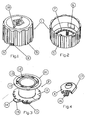
- Said manoeuvring element 1 provides one or more protrusions 6 on the inner surface of the side wall thereof; said protrusions have an oblique surface, ending flush with the wall on its downward-facing side (in respect of fig. 5) and forming an undercut on the opposite side.
- Element 1 further comprises, on the inner surface of the base thereof, a fixed crown of equally-distanced teeth 7; said teeth 7 have differently-bevelled sides, in a clockwise and anti-clockwise direction, for the purpose better described in the following.
- blade 16 is extremely thin and has a pronounced zigzag profile, shaped so as to match slit 9 in enlargement 8 of element 1 is matchingly shaped: in said slit 9 it is in fact impossible to insert any other replacement means, such as the tip of a screwdriver, even a thin one, or a knife blade, while makeshift means such as wire or razor blades, where insertable, are ineffective in establishing an integral connection between the two elements 1 and 2.
Landscapes
- Engineering & Computer Science (AREA)
- Mechanical Engineering (AREA)
- Closures For Containers (AREA)
- Cooling, Air Intake And Gas Exhaust, And Fuel Tank Arrangements In Propulsion Units (AREA)
Claims (13)
- Sicherheitsvorrichtung zum Verschließen, Verbinden und/oder Verriegeln, umfassend:- ein glockenförmiges bewegendes Element (1) und ein bewegtes Element (2) mit einem Gewinde-Ende (3), wobei das Element (2) koaxial in dem bewegenden Element (1) aufgenommen ist,- Mittel (6) zum axialen Verankern der beiden Elemente (1, 2) miteinander, die nicht die freie gegenseitige Drehung derselben verhindern,- erste Mittel (7, 12, 13) zum Verankern des bewegenden Elements (1) mit dem bewegten Element (2) während der Drehung in einer ersten Festziehdrehrichtung lediglich bis zu einem begrenzten Festziehdrehmoment,- wobei die ersten Verankerungsmittel (7, 12, 13) jedoch die freie Drehung des bewegenden Elements (1) in einer zweiten Drehrichtung gestatten, die der ersten Drehrichtung entgegengesetzt ist,- und zweite Mittel (4, 9, 14), die gleichzeitig das bewegende Element (1) und das bewegte Element (2) in wenigstens einer aufeinander abgestimmten Position der Elemente in Eingriff nehmen und sie in wenigstens der zweiten Drehrichtung integral miteinander verbinden, wodurch die zweiten Mittel einen Sitz (9) in Eingriff nehmen, der in dem bewegenden Element (1) ausgebildet ist und ein geformtes Profil aufweist, das genau auf das des Schlüssels abgestimmt ist, und des Weiteren mit wenigstens einem kalibrierten radialen Sitz (14) des bewegten Elements (2), dadurch gekennzeichnet, dass die zweiten Mittel aus einem Schlüssel bestehen, der aus einem dünnen, profilierten, hoch-widerstandsfähigen Blatt hergestellt ist.
- Vorrichtung nach Anspruch 1, wobei das dünne, profilierte, hoch-widerstandsfähige Blatt (16) des Schlüssels (4) aus einem speziellen Stahl hergestellt ist.
- Vorrichtung nach Anspruch 1 oder 2, wobei das Blatt (16) ein quer verlaufendes Zickzackprofil aufweist.
- Vorrichtung nach Anspruch 1, wobei es sich bei dem Sitz (9) und dem radialen Sitz (14) für das dünne profilierte Blatt (16) des Schlüssels (4) um einen Schlitz (9), der in einer Erweiterung (8) am Außenumfang des bewegenden Elements (1) angeordnet ist, bzw. um einen kalibrierten radialen Hohlraum (14) des bewegten Elements (2) handelt.
- Vorrichtung nach Anspruch 4, wobei der kalibrierte radiale Hohlraum (14) in einem zweiten Flansch (11) des bewegten Elements (2) ausgebildet ist, der Vorsprünge (15), die als Index dienen, unter dem Flansch aufweist.
- Sicherheitsvomchtung nach Anspruch 1, dadurch gekennzeichnet, dass die axialen Verankerungsmittel (6) aus einem oder mehreren nachgiebigen Vorsprüngen (6) mit einer schrägen Fläche bestehen, die an der Innenwand des bewegenden Elements (1) ausgebildet sind und in ihrem unteren Abschnitt mit der Wand bündig enden und in ihrem oberen Abschnitt einen Unterschneidungszahn (6) aufweisen, der mit einem Endflansch (10) des bewegten Elements (2) zusammenwirkt.
- Sicherheitsvorrichtung nach Anspruch 1, dadurch gekennzeichnet, dass die ersten Verankerungsmittel (7, 12, 13) wenigstens eine Krone aus Zähnen (7), die zu dem bewegenden Element (1) gehören, und eine Krone aus ähnlichen Zähnen (12), die zu dem bewegten Element (2) gehören, umfassen, wobei jeder Zahn in der Drehrichtung im Uhrzeigersinn und in der Drehrichtung entgegen dem Uhrzeigersinn unterschiedlich geschrägte Flanken aufweist, und die in der Lage sind, sich gegenseitig in Eingriff zu nehmen, wobei jeder Zahn von wenigstens einer der Kronen von einer nachgiebigen Lasche (13) getragen wird.
- Sicherheitsvorrichtung nach Anspruch 1 oder 7, dadurch gekennzeichnet, dass die Flanken der Zähne in der ersten Drehrichtung steil sind, um beim Festziehen bis zu dem begrenzten Festziehdrehmoment miteinander zusammenzuwirken, bzw. eine weniger steile Neigung in der anderen Richtung aufweisen, um eine freie Drehung zu ermöglichen.
- Sicherheitsvorrichtung nach Anspruch 7, dadurch gekennzeichnet, dass die nachgiebigen Laschen von dem bewegten Element getragen werden.
- Sicherheitsvorrichtung nach Anspruch 7, dadurch gekennzeichnet, dass das begrenzte Festziehdrehmoment in der ersten Drehrichtung durch die steile Schräge der Zähne (7, 12) bestimmt wird, die in dieser Drehrichtung miteinander im Eingriff stehen.
- Sicherheitsvorrichtung nach Anspruch 7 oder 9, dadurch gekennzeichnet, dass das begrenzte Festziehdrehmoment in der ersten Drehrichtung durch das Nachgeben der flexiblen Laschen (13) bestimmt wird.
- Vorrichtung nach einem der vorangehenden Ansprüche, wobei das glockenförmige bewegende Element (1) und das bewegte Element (2) aus einem Technopolymer bestehen.
- Vorrichtung nach einem der vorangehenden Ansprüche, wobei ein Index (18) der Position der Erweiterung (8) des bewegenden Elements (1) außen an der Basis des Elements (1) angeordnet ist.
Applications Claiming Priority (2)
| Application Number | Priority Date | Filing Date | Title |
|---|---|---|---|
| IT001945A ITMI20031945A1 (it) | 2003-10-09 | 2003-10-09 | Dispositivo di sicurezza per la chiusura, il collegamento e/o il bloccaggio, in particolare tappo antivandalismo, con coppia limite di serraggio ed apertura forzata non distruttiva impedita |
| ITMI20031945 | 2003-10-09 |
Publications (2)
| Publication Number | Publication Date |
|---|---|
| EP1522500A1 EP1522500A1 (de) | 2005-04-13 |
| EP1522500B1 true EP1522500B1 (de) | 2006-11-02 |
Family
ID=34308127
Family Applications (1)
| Application Number | Title | Priority Date | Filing Date |
|---|---|---|---|
| EP04104706A Expired - Lifetime EP1522500B1 (de) | 2003-10-09 | 2004-09-28 | Sicherheitsverschluss, insbesondere Kappe, mit Drehmomentbegrenzungskupplung und Schutzvorrichtung gegen Zerstörungfreie und unbefugte Handhabung |
Country Status (5)
| Country | Link |
|---|---|
| US (1) | US7413095B2 (de) |
| EP (1) | EP1522500B1 (de) |
| CN (1) | CN1605704B (de) |
| DE (1) | DE602004003014T2 (de) |
| IT (1) | ITMI20031945A1 (de) |
Families Citing this family (16)
| Publication number | Priority date | Publication date | Assignee | Title |
|---|---|---|---|---|
| ITMI20031945A1 (it) | 2003-10-09 | 2005-04-10 | Elesa Spa | Dispositivo di sicurezza per la chiusura, il collegamento e/o il bloccaggio, in particolare tappo antivandalismo, con coppia limite di serraggio ed apertura forzata non distruttiva impedita |
| US20070114506A1 (en) * | 2005-11-06 | 2007-05-24 | Mcneill Peter J | Fence mounting device and associated hardware |
| US8944269B2 (en) * | 2005-11-10 | 2015-02-03 | Vehicle Enhancement Labs | Marine locking gas cap |
| DE102005057360A1 (de) * | 2005-12-01 | 2007-06-06 | Hydac Filtertechnik Gmbh | Verschluss-System für einen Fluidbehälter, insbesondere für Hydrauliktank |
| USD614266S1 (en) * | 2007-06-14 | 2010-04-20 | Michael Joe Lewis | Protective cap for fittings |
| USD615164S1 (en) * | 2009-06-29 | 2010-05-04 | Protective Industries, Inc. | Open ended industrial pipe cap |
| US20110174759A1 (en) * | 2010-01-19 | 2011-07-21 | Titherington Philip D | Senior-Friendly Child-Resistant Cap |
| US9925116B2 (en) | 2014-07-29 | 2018-03-27 | Tri State Distribution, Inc. | Child proof closure |
| EP3612266B1 (de) * | 2017-04-21 | 2023-12-20 | Becton, Dickinson And Company | Anschlusskappe |
| EP3641870B1 (de) * | 2017-06-22 | 2024-05-08 | Becton, Dickinson and Company | Verbinderkappe mit sicherheitsventil |
| EP3617534B1 (de) * | 2018-08-30 | 2022-12-21 | Rohde & Schwarz GmbH & Co. KG | Messvorrichtung, koaxiales hf-verbindungselement und drehmomentbegrenzer für ein koaxiales hf-verbindungselement |
| CN110473338B (zh) * | 2019-08-23 | 2023-11-21 | 深圳市诺丰泰智能科技有限公司 | 一种售货机 |
| USD918014S1 (en) * | 2020-08-31 | 2021-05-04 | Walter Eugene Rabon | Portable spa cover lock |
| CN116615380B (zh) * | 2020-12-18 | 2026-03-31 | 艾尔诺沃股份有限公司 | 防盗用封闭件 |
| US11958364B2 (en) * | 2021-03-05 | 2024-04-16 | Rivian Ip Holdings, Llc | Systems and methods for shaft torque security electrical vehicles |
| US12151861B2 (en) * | 2021-03-16 | 2024-11-26 | Altria Client Services Llc | Tray with base, dome and brim |
Family Cites Families (16)
| Publication number | Priority date | Publication date | Assignee | Title |
|---|---|---|---|---|
| US2772803A (en) * | 1954-12-27 | 1956-12-04 | Frank P Bello | Safety container closure |
| US3160301A (en) * | 1963-10-11 | 1964-12-08 | K C K Holding Company | Container and safety closure therefor |
| US3396864A (en) * | 1967-03-01 | 1968-08-13 | Frederick E. Jones | Safety cap structure |
| US3426932A (en) * | 1967-07-17 | 1969-02-11 | William R Rouse | Tamper-proof poison bottle closure |
| DE7305443U (de) * | 1973-02-14 | 1973-06-07 | Neuro Plast Gmbh & Co Kg | Sicherheits-Flaschenverschluss |
| US4854459A (en) * | 1988-11-18 | 1989-08-08 | Primary Delivery Systems, Inc. | Convertible childproof/non-childproof cap and container |
| US5009338A (en) * | 1989-02-03 | 1991-04-23 | Senetics Corporation | Indicator cap for a medicine bottle |
| US5765706A (en) * | 1989-02-03 | 1998-06-16 | Senetics, Inc. | Flush mounted indicator device |
| US5158194A (en) * | 1991-04-30 | 1992-10-27 | Glaxo Inc. | Safety closure with easy-open feature for handicapped and elderly individuals |
| US5344035A (en) * | 1993-11-10 | 1994-09-06 | Comar Inc. | Child resistant closure |
| US5464109A (en) * | 1994-08-15 | 1995-11-07 | Greenwald; Kenneth | Lockable bottle cap retainer |
| US5769252A (en) * | 1996-12-05 | 1998-06-23 | Volpe And Koenig, P.C. | Container closure which converts from a child resistant to a non-child resistant configuration |
| US6082564A (en) * | 1997-07-29 | 2000-07-04 | Trout; Brett J. | Key actuated locking cap |
| CN1341821A (zh) * | 2000-09-05 | 2002-03-27 | 昆山天星水暖有限公司 | 快速拧紧的管接头 |
| ITMI20031945A1 (it) | 2003-10-09 | 2005-04-10 | Elesa Spa | Dispositivo di sicurezza per la chiusura, il collegamento e/o il bloccaggio, in particolare tappo antivandalismo, con coppia limite di serraggio ed apertura forzata non distruttiva impedita |
| US7043945B2 (en) * | 2004-05-27 | 2006-05-16 | Hollingsworth William L | Handcuff key having extended grip |
-
2003
- 2003-10-09 IT IT001945A patent/ITMI20031945A1/it unknown
-
2004
- 2004-09-28 DE DE602004003014T patent/DE602004003014T2/de not_active Expired - Lifetime
- 2004-09-28 EP EP04104706A patent/EP1522500B1/de not_active Expired - Lifetime
- 2004-09-30 US US10/954,890 patent/US7413095B2/en not_active Expired - Fee Related
- 2004-10-09 CN CN2004100835197A patent/CN1605704B/zh not_active Expired - Lifetime
Also Published As
| Publication number | Publication date |
|---|---|
| EP1522500A1 (de) | 2005-04-13 |
| CN1605704B (zh) | 2010-06-23 |
| DE602004003014T2 (de) | 2007-04-05 |
| ITMI20031945A1 (it) | 2005-04-10 |
| CN1605704A (zh) | 2005-04-13 |
| US7413095B2 (en) | 2008-08-19 |
| DE602004003014D1 (de) | 2006-12-14 |
| US20050077262A1 (en) | 2005-04-14 |
Similar Documents
| Publication | Publication Date | Title |
|---|---|---|
| EP1522500B1 (de) | Sicherheitsverschluss, insbesondere Kappe, mit Drehmomentbegrenzungskupplung und Schutzvorrichtung gegen Zerstörungfreie und unbefugte Handhabung | |
| US4984686A (en) | Sharps container closure and needle extractor assembly | |
| EP0182519B1 (de) | Verschlussanordnung für Behälter | |
| US4126023A (en) | Tamperproof locking and latching mechanism for rotatable controls | |
| US6029834A (en) | Childproof and tamper-proof container closure for containers | |
| TWI345541B (en) | Tamper-evident closure | |
| US5988412A (en) | Safety closure having an internal locking lug | |
| CZ170096A3 (en) | Antiskid detachable obturator of packing | |
| GB2450940A (en) | A tamper-evident closure for a container | |
| JP6608373B2 (ja) | 開栓明示機能を有するクロージャ | |
| EP0950010A1 (de) | Verschluss mit druckausgleichsventil für einen flüssigkeitsbehälter | |
| RU2388673C2 (ru) | Укупорочное средство с индикацией несанкционированного вскрытия | |
| US6123098A (en) | Valve cover | |
| JPS6111358A (ja) | 容器の安全蓋 | |
| US4014449A (en) | Safety cap | |
| US3182840A (en) | Safety bottle closure | |
| US20060130544A1 (en) | Security device for a threaded element | |
| JP3914291B2 (ja) | キャップ用治具 | |
| JPH0626267A (ja) | 警備シール | |
| GB2358626A (en) | Screw on container closures | |
| US2375671A (en) | Tank lock | |
| US4062208A (en) | Locking means for gas valves | |
| EP0345502A1 (de) | Aus zwei ineinander greifenden Komponenten bestehender Garantieverschluss für Behälter | |
| EP0360777A2 (de) | Sicherheitsverschluss für Behälter | |
| EP1063373A1 (de) | Verriegelungsvorrichtung für einen Deckel, insbesondere für einen Schaltschrank |
Legal Events
| Date | Code | Title | Description |
|---|---|---|---|
| PUAI | Public reference made under article 153(3) epc to a published international application that has entered the european phase |
Free format text: ORIGINAL CODE: 0009012 |
|
| AK | Designated contracting states |
Kind code of ref document: A1 Designated state(s): AT BE BG CH CY CZ DE DK EE ES FI FR GB GR HU IE IT LI LU MC NL PL PT RO SE SI SK TR |
|
| AX | Request for extension of the european patent |
Extension state: AL HR LT LV MK |
|
| 17P | Request for examination filed |
Effective date: 20051012 |
|
| AKX | Designation fees paid |
Designated state(s): DE FR IT |
|
| GRAP | Despatch of communication of intention to grant a patent |
Free format text: ORIGINAL CODE: EPIDOSNIGR1 |
|
| GRAS | Grant fee paid |
Free format text: ORIGINAL CODE: EPIDOSNIGR3 |
|
| GRAA | (expected) grant |
Free format text: ORIGINAL CODE: 0009210 |
|
| AK | Designated contracting states |
Kind code of ref document: B1 Designated state(s): DE FR IT |
|
| PG25 | Lapsed in a contracting state [announced via postgrant information from national office to epo] |
Ref country code: IT Free format text: LAPSE BECAUSE OF FAILURE TO SUBMIT A TRANSLATION OF THE DESCRIPTION OR TO PAY THE FEE WITHIN THE PRESCRIBED TIME-LIMIT;WARNING: LAPSES OF ITALIAN PATENTS WITH EFFECTIVE DATE BEFORE 2007 MAY HAVE OCCURRED AT ANY TIME BEFORE 2007. THE CORRECT EFFECTIVE DATE MAY BE DIFFERENT FROM THE ONE RECORDED. Effective date: 20061102 |
|
| REF | Corresponds to: |
Ref document number: 602004003014 Country of ref document: DE Date of ref document: 20061214 Kind code of ref document: P |
|
| ET | Fr: translation filed | ||
| PLBE | No opposition filed within time limit |
Free format text: ORIGINAL CODE: 0009261 |
|
| STAA | Information on the status of an ep patent application or granted ep patent |
Free format text: STATUS: NO OPPOSITION FILED WITHIN TIME LIMIT |
|
| 26N | No opposition filed |
Effective date: 20070803 |
|
| PGRI | Patent reinstated in contracting state [announced from national office to epo] |
Ref country code: IT Effective date: 20081001 |
|
| REG | Reference to a national code |
Ref country code: FR Ref legal event code: PLFP Year of fee payment: 13 |
|
| REG | Reference to a national code |
Ref country code: FR Ref legal event code: PLFP Year of fee payment: 14 |
|
| REG | Reference to a national code |
Ref country code: FR Ref legal event code: PLFP Year of fee payment: 15 |
|
| P01 | Opt-out of the competence of the unified patent court (upc) registered |
Effective date: 20230527 |
|
| PGFP | Annual fee paid to national office [announced via postgrant information from national office to epo] |
Ref country code: IT Payment date: 20230726 Year of fee payment: 20 |
|
| PGFP | Annual fee paid to national office [announced via postgrant information from national office to epo] |
Ref country code: FR Payment date: 20230724 Year of fee payment: 20 Ref country code: DE Payment date: 20230724 Year of fee payment: 20 |
|
| REG | Reference to a national code |
Ref country code: DE Ref legal event code: R071 Ref document number: 602004003014 Country of ref document: DE |