EP1522680A1 - Système de ventilation pour une tuyère d'éjection convergente divergente - Google Patents
Système de ventilation pour une tuyère d'éjection convergente divergente Download PDFInfo
- Publication number
- EP1522680A1 EP1522680A1 EP04292285A EP04292285A EP1522680A1 EP 1522680 A1 EP1522680 A1 EP 1522680A1 EP 04292285 A EP04292285 A EP 04292285A EP 04292285 A EP04292285 A EP 04292285A EP 1522680 A1 EP1522680 A1 EP 1522680A1
- Authority
- EP
- European Patent Office
- Prior art keywords
- flaps
- ring
- divergent
- convergent
- downstream
- Prior art date
- Legal status (The legal status is an assumption and is not a legal conclusion. Google has not performed a legal analysis and makes no representation as to the accuracy of the status listed.)
- Granted
Links
- 238000001816 cooling Methods 0.000 title claims abstract description 31
- 238000011144 upstream manufacturing Methods 0.000 claims description 9
- 238000002485 combustion reaction Methods 0.000 claims description 5
- 230000036555 skin type Effects 0.000 claims description 4
- 230000001360 synchronised effect Effects 0.000 claims description 3
- 238000005192 partition Methods 0.000 description 5
- 230000004907 flux Effects 0.000 description 4
- 238000005070 sampling Methods 0.000 description 3
- 239000007789 gas Substances 0.000 description 2
- 230000001105 regulatory effect Effects 0.000 description 2
- 238000009423 ventilation Methods 0.000 description 2
- 230000009977 dual effect Effects 0.000 description 1
- 230000010354 integration Effects 0.000 description 1
- 239000000203 mixture Substances 0.000 description 1
- 238000010079 rubber tapping Methods 0.000 description 1
- 238000007789 sealing Methods 0.000 description 1
Images


Classifications
-
- F—MECHANICAL ENGINEERING; LIGHTING; HEATING; WEAPONS; BLASTING
- F01—MACHINES OR ENGINES IN GENERAL; ENGINE PLANTS IN GENERAL; STEAM ENGINES
- F01D—NON-POSITIVE DISPLACEMENT MACHINES OR ENGINES, e.g. STEAM TURBINES
- F01D9/00—Stators
- F01D9/06—Fluid supply conduits to nozzles or the like
- F01D9/065—Fluid supply or removal conduits traversing the working fluid flow, e.g. for lubrication-, cooling-, or sealing fluids
-
- F—MECHANICAL ENGINEERING; LIGHTING; HEATING; WEAPONS; BLASTING
- F01—MACHINES OR ENGINES IN GENERAL; ENGINE PLANTS IN GENERAL; STEAM ENGINES
- F01D—NON-POSITIVE DISPLACEMENT MACHINES OR ENGINES, e.g. STEAM TURBINES
- F01D9/00—Stators
- F01D9/06—Fluid supply conduits to nozzles or the like
-
- F—MECHANICAL ENGINEERING; LIGHTING; HEATING; WEAPONS; BLASTING
- F02—COMBUSTION ENGINES; HOT-GAS OR COMBUSTION-PRODUCT ENGINE PLANTS
- F02K—JET-PROPULSION PLANTS
- F02K1/00—Plants characterised by the form or arrangement of the jet pipe or nozzle; Jet pipes or nozzles peculiar thereto
- F02K1/06—Varying effective area of jet pipe or nozzle
- F02K1/12—Varying effective area of jet pipe or nozzle by means of pivoted flaps
- F02K1/1223—Varying effective area of jet pipe or nozzle by means of pivoted flaps of two series of flaps, the upstream series having its flaps hinged at their upstream ends on a fixed structure and the downstream series having its flaps hinged at their upstream ends on the downstream ends of the flaps of the upstream series
-
- F—MECHANICAL ENGINEERING; LIGHTING; HEATING; WEAPONS; BLASTING
- F02—COMBUSTION ENGINES; HOT-GAS OR COMBUSTION-PRODUCT ENGINE PLANTS
- F02K—JET-PROPULSION PLANTS
- F02K1/00—Plants characterised by the form or arrangement of the jet pipe or nozzle; Jet pipes or nozzles peculiar thereto
- F02K1/28—Plants characterised by the form or arrangement of the jet pipe or nozzle; Jet pipes or nozzles peculiar thereto using fluid jets to influence the jet flow
- F02K1/30—Plants characterised by the form or arrangement of the jet pipe or nozzle; Jet pipes or nozzles peculiar thereto using fluid jets to influence the jet flow for varying effective area of jet pipe or nozzle
-
- F—MECHANICAL ENGINEERING; LIGHTING; HEATING; WEAPONS; BLASTING
- F02—COMBUSTION ENGINES; HOT-GAS OR COMBUSTION-PRODUCT ENGINE PLANTS
- F02K—JET-PROPULSION PLANTS
- F02K1/00—Plants characterised by the form or arrangement of the jet pipe or nozzle; Jet pipes or nozzles peculiar thereto
- F02K1/78—Other construction of jet pipes
- F02K1/80—Couplings or connections
-
- F—MECHANICAL ENGINEERING; LIGHTING; HEATING; WEAPONS; BLASTING
- F02—COMBUSTION ENGINES; HOT-GAS OR COMBUSTION-PRODUCT ENGINE PLANTS
- F02K—JET-PROPULSION PLANTS
- F02K1/00—Plants characterised by the form or arrangement of the jet pipe or nozzle; Jet pipes or nozzles peculiar thereto
- F02K1/78—Other construction of jet pipes
- F02K1/82—Jet pipe walls, e.g. liners
- F02K1/822—Heat insulating structures or liners, cooling arrangements, e.g. post combustion liners; Infrared radiation suppressors
-
- Y—GENERAL TAGGING OF NEW TECHNOLOGICAL DEVELOPMENTS; GENERAL TAGGING OF CROSS-SECTIONAL TECHNOLOGIES SPANNING OVER SEVERAL SECTIONS OF THE IPC; TECHNICAL SUBJECTS COVERED BY FORMER USPC CROSS-REFERENCE ART COLLECTIONS [XRACs] AND DIGESTS
- Y02—TECHNOLOGIES OR APPLICATIONS FOR MITIGATION OR ADAPTATION AGAINST CLIMATE CHANGE
- Y02T—CLIMATE CHANGE MITIGATION TECHNOLOGIES RELATED TO TRANSPORTATION
- Y02T50/00—Aeronautics or air transport
- Y02T50/60—Efficient propulsion technologies, e.g. for aircraft
Definitions
- the invention relates to a ventilation system for a nozzle convergent divergent equipping a turbojet for military use.
- turbofan engine having an X-axis post-combustion chamber delimited by a annular wall located radially inside an annular housing, said annular wall and said housing defining an annular passage in which circulates a flow of cooling air, an axisymmetrical nozzle convergent divergent disposed downstream of said post-combustion chamber and having a crown of convergent flaps hinged to the downstream end of said housing and a ring of divergent hinged flaps at the downstream end of said convergent flaps, each crown of flaps alternately comprising a plurality of controlled flaps and a a plurality of follower flaps, a crown of cold flaps arranged radially outside said nozzle and hinged at their end upstream on a conical shell connected to the downstream portion of said housing, means for creating a cooling air film on the internal faces said convergent flaps and means for cooling said divergent shutters.
- US 5,435,127 relates to a turbojet of the type mentioned above in which the cooling of the divergent flaps is carried out by a mixture of nacelle airflow with a sample of air in the downstream part of the annular channel in which the cooling flow circulates of the annular wall.
- the air intake is operated directly by tapping on the channel with an adjustment valve at the quilting outlet. Downstream of the elbow of stitching is placed a jet trunk which carries out the mixing between high pressure air motor and unpressurized aerial platform.
- the exact conformation of the levy is not indicated in this document.
- direct sampling on the channel may not be be effective in taking large amounts of flow on the flow cooling, because it disrupts the operation of the ventilation. he risk of reintroductions of hot gases under the annular wall and poor power supply of the shutter cooling film converged.
- the object of the invention is to feed efficiently and uniformly the divergent flaps of a converging divergent nozzle cooled with a device that has a high rate of integration with parts existing.
- the structure of the plenum and alveoli is constituted by the conical shell and by walls which reinforce the conical shell.
- the shutters divergent followers are powered by a cooling air pressurized from the annular channel delimited by the annular wall and the casing.
- the plenum helps slow down the speed of Received air and increase the air pressure cooling shutters divergent followers.
- the cooling means of the shutters diverging means furthermore comprise means for regulating the air flow of cooling said shutters.
- the flow control means preferably comprise a mobile mounted ring in a drawer secured to the boundary wall, said ring and said drawer each having a plurality of adjustment holes flow rates that can be matched to the drill holes the boundary wall by moving said ring.
- the ring is mounted mobile in rotation about the axis X and is rotated by a rack and pinion system by means of an actuator driving said pinion.
- the ring is mounted mobile in translation parallel to the X axis and is moved by a a plurality of synchronized cylinders.
- FIG. 1 shows the rear body 1 of a turbojet engine dual flow aircraft that has an afterburner chamber 2 of axis X in which circulates the hot primary flow F1.
- This post-combustion chamber 2 is delimited by a annular wall 3 of X axis arranged radially inside a housing 4.
- the annular wall 3 and the casing 4 delimit between them an annular channel 6 in which circulates a cold secondary flow F2, used for cooling of the annular wall 3 and a divergent converging nozzle 10 disposed downstream of the afterburner chamber 2.
- This convergent divergent nozzle 10 comprises a first crown of convergent shutters with convergent shutters 11, articulated on the downstream end of the casing 4 and alternating circumferentially with convergent flaps follower 12 also articulated on the downstream end of the casing 4, and a second ring of divergent shutters with alternating divergent shutters 13 articulated at the downstream end of the convergent flaps 11, and follower divergent flaps 14 hinged at the end downstream of the follower convergent flaps 12, the number of convergent flaps being even and equal to the number of divergent components.
- nozzle 10 Around the nozzle 10 are provided cold shutters 15 hinged at their downstream end on a conical shell 16 integral with the downstream part of the casing 4.
- a ring 20 which shares the cold secondary flow F2 into a radially inner flow F3 which leads through a slot tangentially to the inner wall of the shutters convergent, so as to form a film of cold air driven by the flow F1 and licking the convergent flaps, the latter being able to be of the single skin type, and in a radially outward flow F4 intended cooling the divergent flaps.
- the flow F4 penetrates through openings 21 formed in the end wall 22 of the casing 4 located downstream of the conical shell 16, in a chamber annular of tranquilization 23 of axis X, delimited upstream by the part radially inner 17 of the conical shell 16, and downstream by the fastening structure 24 of the convergent divergent nozzle 10, integral with the casing 4.
- the end wall 22, having the openings 21, forms the boundary between the annular channel 6 and the chamber of tranquilization 23.
- Each cell 30 is delimited in upstream by a median portion 18 of the conical shell 16, and circumferentially by two substantially parallel walls 19 forming the conical ferrule 16, as can be seen in the figure 4. It is bounded downstream by a closure wall 31 which connects the fastening structure 24 at the upper part 32 of the conical shell 16, this closure wall 31 having an orifice 33 whose use will be explained later in this memo.
- the chamber of tranquilization 23 is closed by a substantially axial wall 34, visible in Figure 4, which connects the radially inner ends of two adjacent walls 19.
- FIGS. 3 and 4 also show that the conical ferrule 16 further has a wall 35, strongly inclined which extends between the downstream edge of the axial wall 34, the downstream edges of said two walls 19 adjacent and the upstream edge of the upper part 32, between two adjacent cells.
- This wall 35 has several orifices 36 allowing the circulation of the non-pressurized nacelle F5 air in order to to cool the various control devices of the flaps of the nozzle divergent convergent 10.
- the orifice 33 of each cell has a connection 40 for the fixing the upstream end of a pipe or telescopic tube 41 connected to the follower divergent flap 14 located in the same axial plane passing through the X axis.
- the follower divergent flaps 14 are of the boxed type and the interior of these flaps 14 receives a portion of the air flow F4 which is pressurized. Appropriate orifices allow the evacuation of this air into the F1 flow and to the inner wall of the controlled divergent flaps 13 which can advantageously be of the simple skin type.
- the radially external flow F4 is injected into the chamber of still 23 through the partition wall 22 breakthrough.
- the F4 flow divides then leaving the chamber 23 between the different cells 30 serving to feed the telescopic tubes 41 and then the shutters divergent followers 14.
- the plenum 23 allows to do a regular sampling at the end of the annular channel 6 and to supply cells 30 with a uniform pressure and flow rate. Of the so, the cooling film of the inner walls of the shutters convergent 11 and 12 is not disturbed even in case of strong sampling F4 flow.
- the shape given to the conical ferrule 16 as well as that is visible in FIG. 4 makes it possible to produce the cooling circuit diverging flaps 13, 14 without excessive clutter and allows rigidify this conical shell 16, thanks to the partitions 19 delimiting the cavities 30 and the walls 35.
- a device 50 is furthermore provided. to progressively control the F4 flow injected at the level of follower divergent flaps 14.
- This device 50 comprises a ring ordered 51 to seal the entrance to the chamber of 23 tranquilization according to the flight conditions.
- the shutter does not need to be of a great seal, because the goal is to reduce appreciable F4 cooling flow, which is costly for the performance under certain operating conditions of the engine.
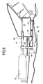
- FIG. 5 shows a first embodiment of the device 50.
- the ring 51 is rotatably mounted about the X axis and its position is adjusted by an actuator 52.
- the ring 51 is located radially inside of the boundary partition 22 facing the openings 21.
- On its face lower, the ring 51 is held in place by another fixed partition 53 in which are made openings 54 opposite the openings 21.
- a pinion 55 mounted on the rod of the actuator 52 drives the ring 51 in rotation by means of a rack secured to the ring 51. sealing segments 56 limit leaks between the ring 51 and the still room 23 when it is closed.
- the ring 51 also has openings 57 which, in the maximum flow position, are aligned with the openings 21 and 54.
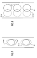
- the openings 57 offset circumferentially with respect to openings 21 and 54, as shown in FIG. 7, between the open position maximum and a total closure position, in which there is no virtually more flow, except for leaks. It is thus possible to dose the flow continuously.
- Figure 6 shows a second embodiment of the device 50 which also comprises a ring 51 having openings 57 likely to be disposed opposite openings 21 of the boundary wall 22 and openings 54 of a fixed partition 53 secured to the downstream end of the casing 4.
- the ring is likely to be moved parallel to the X axis by means of a plurality of synchronized cylinders 60, for example three cylinders, of which the pins 61 slide in guides 62.
- the connection between the axes 61 and the ring is made by means of rods 63 passing through the casing 4 by means watertight passages 64.
- the openings 57 are disposed opposite the openings 21 and 54 and the system is debiting.
- openings 21 and 54 are closed by the ring 51 and there is practically no no flow, except leak rates.
- FIG. 8 it is possible to dose the air flow keep on going.
- the seals between the ring 51 and the fixed parts can be ensured by segments, to delay a rapid wear of the joints.
- the device 50 offers the possibility of regulating the flow taken in a certain range to adapt it to the conditions of engine operation and operational circumstances.
Landscapes
- Engineering & Computer Science (AREA)
- Mechanical Engineering (AREA)
- General Engineering & Computer Science (AREA)
- Chemical & Material Sciences (AREA)
- Combustion & Propulsion (AREA)
- Physics & Mathematics (AREA)
- Fluid Mechanics (AREA)
- Structures Of Non-Positive Displacement Pumps (AREA)
- Turbine Rotor Nozzle Sealing (AREA)
- Cylinder Crankcases Of Internal Combustion Engines (AREA)
Abstract
Description
- les volets divergents suiveurs sont caissonnés et refroidis par l'air délivré par les canalisations télescopiques, tandis que les volets divergents commandés sont à simple peau ;
- les volets convergents sont du type simple peau ;
- la paroi conique comporte des ouvertures entre les alvéoles pour permettre la circulation d'un air de nacelle dans l'espace entourant la tuyère convergente divergente ;
- le flux d'air de refroidissement, circulant dans le canal annulaire est divisé en deux flux au moyen d'un anneau fixe solidaire de la paroi frontière, le flux radialement intérieur étant injecté en amont des volets convergents via une fente et le flux radialement extérieur étant injecté dans la chambre de tranquillisation par les perçages ménagés dans la paroi frontière.
Claims (9)
- Turboréacteur à double flux comportant une chambre de post-combustion (2) d'axe X délimitée par une paroi annulaire (3) située radialement à l'intérieur d'un carter annulaire (4), ladite paroi annulaire et ledit carter définissant un passage annulaire (6) dans lequel circule un flux d'air de refroidissement (F2), une tuyère axisymétrique (10) convergente divergente disposée en aval de ladite chambre de post-combustion (2) et comportant une couronne de volets convergents (11, 12) articulés à l'extrémité aval dudit carter (4) et une couronne de volets divergents (13, 14) articulés à l'extrémité aval desdits volets convergents (11, 12), chaque couronne de volets comportant en alternance une pluralité de volets commandés (11, 13) et une pluralité de volets suiveurs (12, 14), une couronne de volets froids (15) disposés radialement à l'extérieur de ladite tuyère (10) et articulés à leur extrémité amont sur une virole conique (16) raccordée à la partie aval dudit carter (4), des moyens pour créer un film d'air de refroidissement sur les faces internes desdits volets convergents (11 , 12) et des moyens de refroidissement desdits volets divergents (13, 14), caractérisé par le fait que les moyens de refroidissement desdits volets divergents (13, 14) comportent :une chambre de tranquillisation (23) annulaire délimitée en aval par ladite virole conique (16) et alimentée en air de refroidissement par des perçages (21) ménagés dans une paroi frontière (22) entre ladite chambre de tranquillisation (23) et l'extrémité aval dudit passage annulaire (6),une pluralité d'alvéoles de distribution (30) entourant la chambre de tranquillisation (23) et raccordées à cette dernière, lesdites alvéoles (30) étant délimitées en aval par ladite virole conique (16) et étant disposées autour de l'axe X dans les plans de symétrie des volets suiveurs (12, 14), etdes canalisations télescopiques (41) raccordant chacune une alvéole (30) au volet divergent suiveur (14) situé dans le même plan de symétrie que ladite alvéole (30).
- Turboréacteur selon la revendication 1, caractérisé par le fait que les volets divergents suiveurs (14) sont caissonnés et refroidis par l'air délivré par les canalisations télescopiques (41) tandis que les volets divergents commandés (13) sont à simple peau.
- Turboréacteur selon l'une des revendications 1 ou 2, caractérisé par le fait que les volets convergents (11, 12) sont du type simple peau.
- Turboréacteur selon l'une quelconque des revendications 1 à 3, caractérisé par le fait que la paroi conique (16) comporte des ouvertures entre les alvéoles pour permettre la circulation d'un air de nacelle dans l'espace entourant la tuyère convergente divergente.
- Turboréacteur selon l'une quelconque des revendications 1 à 4, caractérisé par le fait que le flux d'air de refroidissement (F2) circulant dans le canal annulaire (6) est divisé en deux flux au moyen d'un anneau fixe (20) solidaire de la paroi frontière (22), le flux radialement intérieur (F3) étant injecté en amont des volets convergents (11, 12) via une fente et le flux radialement extérieur (F4) étant injecté dans la chambre de tranquillisation (23) par les perçages (21) de la paroi frontière (22).
- Turboréacteur selon la revendication 5, caractérisé par le fait que les moyens de refroidissement des volets divergents (13, 14) comportent en outre des moyens (50) pour régler le débit d'air de refroidissement (F4) desdits volets.
- Turboréacteur selon la revendication 6, caractérisé par le fait que les moyens de réglage de débit (50) comportent un anneau (51) monté mobile dans un tiroir (53) solidaire de la paroi frontière (22), ledit anneau (51) et ledit tiroir (53) comportant chacun une pluralité de trous de réglage (54, 57) de débit susceptibles d'être mis en correspondance avec les perçages (21) de la paroi frontière (22) par déplacement dudit anneau (51).
- Turboréacteur selon la revendication 7, caractérisé par le fait que l'anneau (51) est monté mobile en rotation autour de l'axe X et est entraíné en rotation par un système pignon (55) crémaillère au moyen d'un actionneur (52) entraínant ledit pignon (55).
- Turboréacteur selon la revendication 7, caractérisé par le fait que l'anneau (51) est monté mobile en translation parallèlement à l'axe X et est déplacé par une pluralité de vérins synchronisés (60).
Applications Claiming Priority (2)
| Application Number | Priority Date | Filing Date | Title |
|---|---|---|---|
| FR0311187 | 2003-09-24 | ||
| FR0311187A FR2860045B1 (fr) | 2003-09-24 | 2003-09-24 | Systeme de ventilation pour une tuyere d'ejection convergente divergente |
Publications (2)
| Publication Number | Publication Date |
|---|---|
| EP1522680A1 true EP1522680A1 (fr) | 2005-04-13 |
| EP1522680B1 EP1522680B1 (fr) | 2008-04-09 |
Family
ID=34224442
Family Applications (1)
| Application Number | Title | Priority Date | Filing Date |
|---|---|---|---|
| EP04292285A Expired - Lifetime EP1522680B1 (fr) | 2003-09-24 | 2004-09-23 | Système de ventilation pour une tuyère d'éjection convergente divergente |
Country Status (4)
| Country | Link |
|---|---|
| US (1) | US7296397B2 (fr) |
| EP (1) | EP1522680B1 (fr) |
| ES (1) | ES2308126T3 (fr) |
| FR (1) | FR2860045B1 (fr) |
Cited By (4)
| Publication number | Priority date | Publication date | Assignee | Title |
|---|---|---|---|---|
| EP1719878A3 (fr) * | 2005-04-28 | 2009-09-16 | United Technologies Corporation | Ensemble de soupape d'air pour turbine à gaz |
| FR2933128A1 (fr) * | 2008-06-25 | 2010-01-01 | Snecma | Dispositif de prelevement d'air de refroidissement dans une turbomachine |
| FR2933127A1 (fr) * | 2008-06-25 | 2010-01-01 | Snecma | Dispositif de prelevement d'air de refroidissement dans une turbomachine |
| FR2952434A1 (fr) * | 2009-11-12 | 2011-05-13 | Snecma | Grille de distorsion apte a regler l'obstruction d'un flux d'air dans un turboreacteur |
Families Citing this family (14)
| Publication number | Priority date | Publication date | Assignee | Title |
|---|---|---|---|---|
| US7207352B2 (en) * | 2005-05-02 | 2007-04-24 | United Technologies Corporation | Bushing for thermally independent bypass air metering valve |
| FR2900444B1 (fr) * | 2006-04-28 | 2008-06-13 | Snecma Sa | Turboreacteur comprenant un canal de post combustion refroidi par un flux de ventilation a debit variable |
| US7854124B2 (en) * | 2006-10-27 | 2010-12-21 | United Technologies Corporation | Combined control for supplying cooling air and support air in a turbine engine nozzle |
| US7757477B2 (en) * | 2007-02-20 | 2010-07-20 | United Technologies Corporation | Convergent divergent nozzle with slot cooled nozzle liner |
| FR2915550B1 (fr) | 2007-04-27 | 2012-05-11 | Snecma | Vanne a clapet pour un systeme de refroidissement dans une turbomachine |
| US8096104B2 (en) * | 2007-05-31 | 2012-01-17 | United Technologies Corporation | Fluidic vectoring for exhaust nozzle |
| FR2937679B1 (fr) * | 2008-10-24 | 2010-12-03 | Snecma | Dispositif de prelevement d'air de refroidissement dans une turbomachine |
| US10087884B2 (en) * | 2014-12-15 | 2018-10-02 | United Technologies Corporation | Stepped fairing modulated exhaust cooling |
| FR3100286B1 (fr) * | 2019-08-30 | 2021-09-17 | Safran Aircraft Engines | Couple volet convergent-volet divergent pour tuyère de turboréacteur à géométrie variable comprenant des conduits de circulation d’air de refroidissement raccordés au travers de surfaces de contact |
| FR3129987B1 (fr) * | 2021-12-03 | 2025-04-11 | Safran Aircraft Engines | Tuyere d’echappement de gaz de combustion pour une turbomachine d’aeronef |
| CN114526175B (zh) * | 2022-04-24 | 2022-07-26 | 中国航发四川燃气涡轮研究院 | 一种用于加力燃烧室的齿轮传动后涵道引射器 |
| CN115013182B (zh) * | 2022-06-17 | 2025-12-05 | 中国航发贵阳发动机设计研究所 | 一种高效冷却的喷气发动机 |
| FR3146712B1 (fr) * | 2023-03-13 | 2025-03-14 | Safran Aircraft Engines | Turboréacteur comportant une chambre de postcombustion ayant un diaphragme coopérant avec une chemise pour conditionner sa section de passage à la dilatation axiale de la chemise |
| FR3146711A1 (fr) * | 2023-03-13 | 2024-09-20 | Safran Aircraft Engines | Turboréacteur comportant une chambre de postcombustion ayant une chemise maintenue radialement par des pontets intégrés à diaphragme |
Citations (6)
| Publication number | Priority date | Publication date | Assignee | Title |
|---|---|---|---|---|
| US4000612A (en) * | 1975-07-28 | 1977-01-04 | General Electric Company | Cooling system for a thrust vectoring gas turbine engine exhaust system |
| EP0541346A1 (fr) * | 1991-11-05 | 1993-05-12 | General Electric Company | Appareil pour le transfert de fluide |
| US5603531A (en) * | 1994-12-06 | 1997-02-18 | United Technologies Corporation | Blind assembly-swivel crossover tube |
| US5996936A (en) * | 1997-09-29 | 1999-12-07 | General Electric Company | Fluidic throat exhaust nozzle |
| US6021637A (en) * | 1997-09-29 | 2000-02-08 | General Electric Company | Integrated fluidic CD nozzle for gas turbine engine |
| EP1333172A1 (fr) * | 2002-01-31 | 2003-08-06 | Snecma Moteurs | Système de refroidissement pour une tuyère de post-combustion de turbomachine |
Family Cites Families (7)
| Publication number | Priority date | Publication date | Assignee | Title |
|---|---|---|---|---|
| US5720434A (en) * | 1991-11-05 | 1998-02-24 | General Electric Company | Cooling apparatus for aircraft gas turbine engine exhaust nozzles |
| US5435127A (en) * | 1993-11-15 | 1995-07-25 | General Electric Company | Method and apparatus for boosting ram airflow to an ejection nozzle |
| US5593112A (en) * | 1994-12-06 | 1997-01-14 | United Technologies Corporation | Nacelle air pump for vector nozzles for aircraft |
| US5586431A (en) * | 1994-12-06 | 1996-12-24 | United Technologies Corporation | Aircraft nacelle ventilation and engine exhaust nozzle cooling |
| US6301877B1 (en) * | 1995-11-13 | 2001-10-16 | United Technologies Corporation | Ejector extension cooling for exhaust nozzle |
| US5799874A (en) * | 1995-11-30 | 1998-09-01 | United Technologies Corporation | Aerodynamically controlled ejector |
| FR2865000B1 (fr) * | 2004-01-12 | 2006-06-09 | Snecma Moteurs | Dispositif d'alimentation en air de refroidissement de volets de tuyere |
-
2003
- 2003-09-24 FR FR0311187A patent/FR2860045B1/fr not_active Expired - Fee Related
-
2004
- 2004-09-22 US US10/945,917 patent/US7296397B2/en active Active
- 2004-09-23 ES ES04292285T patent/ES2308126T3/es not_active Expired - Lifetime
- 2004-09-23 EP EP04292285A patent/EP1522680B1/fr not_active Expired - Lifetime
Patent Citations (6)
| Publication number | Priority date | Publication date | Assignee | Title |
|---|---|---|---|---|
| US4000612A (en) * | 1975-07-28 | 1977-01-04 | General Electric Company | Cooling system for a thrust vectoring gas turbine engine exhaust system |
| EP0541346A1 (fr) * | 1991-11-05 | 1993-05-12 | General Electric Company | Appareil pour le transfert de fluide |
| US5603531A (en) * | 1994-12-06 | 1997-02-18 | United Technologies Corporation | Blind assembly-swivel crossover tube |
| US5996936A (en) * | 1997-09-29 | 1999-12-07 | General Electric Company | Fluidic throat exhaust nozzle |
| US6021637A (en) * | 1997-09-29 | 2000-02-08 | General Electric Company | Integrated fluidic CD nozzle for gas turbine engine |
| EP1333172A1 (fr) * | 2002-01-31 | 2003-08-06 | Snecma Moteurs | Système de refroidissement pour une tuyère de post-combustion de turbomachine |
Cited By (6)
| Publication number | Priority date | Publication date | Assignee | Title |
|---|---|---|---|---|
| EP1719878A3 (fr) * | 2005-04-28 | 2009-09-16 | United Technologies Corporation | Ensemble de soupape d'air pour turbine à gaz |
| FR2933128A1 (fr) * | 2008-06-25 | 2010-01-01 | Snecma | Dispositif de prelevement d'air de refroidissement dans une turbomachine |
| FR2933127A1 (fr) * | 2008-06-25 | 2010-01-01 | Snecma | Dispositif de prelevement d'air de refroidissement dans une turbomachine |
| US8408009B2 (en) | 2008-06-25 | 2013-04-02 | Snecma | Cooling air bleed device in a turbine engine |
| US8448448B2 (en) | 2008-06-25 | 2013-05-28 | Snecma | Cooling air bleed device in a turbomachine |
| FR2952434A1 (fr) * | 2009-11-12 | 2011-05-13 | Snecma | Grille de distorsion apte a regler l'obstruction d'un flux d'air dans un turboreacteur |
Also Published As
| Publication number | Publication date |
|---|---|
| US20050091964A1 (en) | 2005-05-05 |
| FR2860045B1 (fr) | 2006-01-06 |
| US7296397B2 (en) | 2007-11-20 |
| FR2860045A1 (fr) | 2005-03-25 |
| EP1522680B1 (fr) | 2008-04-09 |
| ES2308126T3 (es) | 2008-12-01 |
Similar Documents
| Publication | Publication Date | Title |
|---|---|---|
| EP1522680B1 (fr) | Système de ventilation pour une tuyère d'éjection convergente divergente | |
| CA2933353C (fr) | Turbomachine d'aeronef comportant un echangeur de chaleur du type pre-refroidisseur | |
| EP4166771B1 (fr) | Ensemble propulsif pour aéronef | |
| EP4259915B1 (fr) | Échangeur de chaleur monté dans une cavité d'une turbomachine | |
| CA2416251C (fr) | Dispositif de refroidissement de la tuyere commune sur une nacelle de turboreacteur | |
| CA2652363A1 (fr) | Nacelle de turboreacteur equipee de moyens de reduction du bruit engendre par ce turboreacteur | |
| FR3057620A1 (fr) | Ensemble propulsif comprenant un conduit d'alimentation du generateur de gaz dans un carter inter-veine | |
| FR3019855A1 (fr) | Ensemble propulsif d'aeronef comprenant une vanne d'air a debit variable | |
| CA2677423A1 (fr) | Nacelle de moteur a reaction pour un avion | |
| CA2813559A1 (fr) | Nacelle de turboreacteur a section de sortie de ventilation adaptable | |
| FR2940396A1 (fr) | Vanne d'alimentation en fluide d'une charge, echangeur de chaleur alimente par la vanne et moteur thermique a combustion interne comportant la vanne | |
| EP4124738A1 (fr) | Ensemble propulsif pour aéronef | |
| FR2721693A1 (fr) | Procédé et dispositif pour alimenter en carburant et refroidir l'injecteur de décollage d'une chambre de combustion à deux têtes. | |
| CA2875044A1 (fr) | Carter pour un ensemble propulsif | |
| FR2855559A1 (fr) | Systeme d'etancheite du flux secondaire a l'entree d'une tuyere d'une turbomachine avec chambre de post-combustion | |
| EP1956226B1 (fr) | Dispositif de décharge pour un turboréacteur, et turboréacteur le comportant | |
| EP3487764B1 (fr) | Nacelle de turbomoteur comportant un dispositif de refroidissement | |
| FR3009027A1 (fr) | Ensemble turbomachine d'aeronef a bruit de jet attenue. | |
| FR3072127B1 (fr) | Conduit de decharge d'un moyeu de carter intermediaire pour turboreacteur d'aeronef comportant des canaux de refroidissement | |
| EP3717765A1 (fr) | Nacelle de turboreacteur comportant un cadre mobile unique d'inverseur de poussee a grilles et des passages de servitudes | |
| FR3069609B1 (fr) | Vanne de dosage de fluide | |
| EP2859214A1 (fr) | Systeme de recuperation d'energie dans un circuit de gaz d'echappement | |
| EP3647636B1 (fr) | Vanne de régulation d'un flux de fluide equipée d'un actionneur électrique et système comprenant une telle vanne | |
| FR3008500A1 (fr) | Trompe de melange de gaz destinee notamment a un systeme de chauffage | |
| FR3033616B1 (fr) | Vanne d'adaptation du debit moteur |
Legal Events
| Date | Code | Title | Description |
|---|---|---|---|
| PUAI | Public reference made under article 153(3) epc to a published international application that has entered the european phase |
Free format text: ORIGINAL CODE: 0009012 |
|
| 17P | Request for examination filed |
Effective date: 20041001 |
|
| AK | Designated contracting states |
Kind code of ref document: A1 Designated state(s): AT BE BG CH CY CZ DE DK EE ES FI FR GB GR HU IE IT LI LU MC NL PL PT RO SE SI SK TR |
|
| AX | Request for extension of the european patent |
Extension state: AL HR LT LV MK |
|
| RAP1 | Party data changed (applicant data changed or rights of an application transferred) |
Owner name: SNECMA |
|
| AKX | Designation fees paid |
Designated state(s): ES FR GB |
|
| REG | Reference to a national code |
Ref country code: DE Ref legal event code: 8566 |
|
| GRAP | Despatch of communication of intention to grant a patent |
Free format text: ORIGINAL CODE: EPIDOSNIGR1 |
|
| GRAS | Grant fee paid |
Free format text: ORIGINAL CODE: EPIDOSNIGR3 |
|
| GRAA | (expected) grant |
Free format text: ORIGINAL CODE: 0009210 |
|
| AK | Designated contracting states |
Kind code of ref document: B1 Designated state(s): ES FR GB |
|
| REG | Reference to a national code |
Ref country code: GB Ref legal event code: FG4D Free format text: NOT ENGLISH |
|
| REG | Reference to a national code |
Ref country code: ES Ref legal event code: FG2A Ref document number: 2308126 Country of ref document: ES Kind code of ref document: T3 |
|
| PLBE | No opposition filed within time limit |
Free format text: ORIGINAL CODE: 0009261 |
|
| STAA | Information on the status of an ep patent application or granted ep patent |
Free format text: STATUS: NO OPPOSITION FILED WITHIN TIME LIMIT |
|
| 26N | No opposition filed |
Effective date: 20090112 |
|
| PGFP | Annual fee paid to national office [announced via postgrant information from national office to epo] |
Ref country code: ES Payment date: 20120910 Year of fee payment: 9 |
|
| REG | Reference to a national code |
Ref country code: ES Ref legal event code: FD2A Effective date: 20150406 |
|
| PG25 | Lapsed in a contracting state [announced via postgrant information from national office to epo] |
Ref country code: ES Free format text: LAPSE BECAUSE OF NON-PAYMENT OF DUE FEES Effective date: 20130924 |
|
| REG | Reference to a national code |
Ref country code: FR Ref legal event code: PLFP Year of fee payment: 13 |
|
| REG | Reference to a national code |
Ref country code: FR Ref legal event code: PLFP Year of fee payment: 14 |
|
| REG | Reference to a national code |
Ref country code: FR Ref legal event code: CD Owner name: SAFRAN AIRCRAFT ENGINES Effective date: 20170719 |
|
| REG | Reference to a national code |
Ref country code: FR Ref legal event code: PLFP Year of fee payment: 15 |
|
| PGFP | Annual fee paid to national office [announced via postgrant information from national office to epo] |
Ref country code: GB Payment date: 20230823 Year of fee payment: 20 |
|
| PGFP | Annual fee paid to national office [announced via postgrant information from national office to epo] |
Ref country code: FR Payment date: 20230822 Year of fee payment: 20 |
|
| PG25 | Lapsed in a contracting state [announced via postgrant information from national office to epo] |
Ref country code: GB Free format text: LAPSE BECAUSE OF EXPIRATION OF PROTECTION Effective date: 20240922 |
|
| REG | Reference to a national code |
Ref country code: GB Ref legal event code: PE20 Expiry date: 20240922 |
|
| PG25 | Lapsed in a contracting state [announced via postgrant information from national office to epo] |
Ref country code: GB Free format text: LAPSE BECAUSE OF EXPIRATION OF PROTECTION Effective date: 20240922 |