EP1522727A2 - Pompe de dosage - Google Patents
Pompe de dosage Download PDFInfo
- Publication number
- EP1522727A2 EP1522727A2 EP04023691A EP04023691A EP1522727A2 EP 1522727 A2 EP1522727 A2 EP 1522727A2 EP 04023691 A EP04023691 A EP 04023691A EP 04023691 A EP04023691 A EP 04023691A EP 1522727 A2 EP1522727 A2 EP 1522727A2
- Authority
- EP
- European Patent Office
- Prior art keywords
- syringes
- dosing pump
- pump according
- base plate
- control device
- Prior art date
- Legal status (The legal status is an assumption and is not a legal conclusion. Google has not performed a legal analysis and makes no representation as to the accuracy of the status listed.)
- Withdrawn
Links
Images



Classifications
-
- F—MECHANICAL ENGINEERING; LIGHTING; HEATING; WEAPONS; BLASTING
- F04—POSITIVE - DISPLACEMENT MACHINES FOR LIQUIDS; PUMPS FOR LIQUIDS OR ELASTIC FLUIDS
- F04B—POSITIVE-DISPLACEMENT MACHINES FOR LIQUIDS; PUMPS
- F04B7/00—Piston machines or pumps characterised by having positively-driven valving
- F04B7/0019—Piston machines or pumps characterised by having positively-driven valving a common distribution member forming a single discharge distributor for a plurality of pumping chambers
- F04B7/0026—Piston machines or pumps characterised by having positively-driven valving a common distribution member forming a single discharge distributor for a plurality of pumping chambers and having an oscillating movement
-
- F—MECHANICAL ENGINEERING; LIGHTING; HEATING; WEAPONS; BLASTING
- F04—POSITIVE - DISPLACEMENT MACHINES FOR LIQUIDS; PUMPS FOR LIQUIDS OR ELASTIC FLUIDS
- F04B—POSITIVE-DISPLACEMENT MACHINES FOR LIQUIDS; PUMPS
- F04B13/00—Pumps specially modified to deliver fixed or variable measured quantities
-
- F—MECHANICAL ENGINEERING; LIGHTING; HEATING; WEAPONS; BLASTING
- F04—POSITIVE - DISPLACEMENT MACHINES FOR LIQUIDS; PUMPS FOR LIQUIDS OR ELASTIC FLUIDS
- F04B—POSITIVE-DISPLACEMENT MACHINES FOR LIQUIDS; PUMPS
- F04B13/00—Pumps specially modified to deliver fixed or variable measured quantities
- F04B13/02—Pumps specially modified to deliver fixed or variable measured quantities of two or more fluids at the same time
Definitions
- the invention relates to a metering pump, in particular for very small quantities.
- the invention provides a dosing pump to be proposed, which has a simple structure has and can be used in conventional syringes as pumping elements.
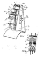
- FIG. 1 shows a front view of the metering pump without the syringes inserted therein, which are shown in FIG. 1a are shown schematically.
- a base plate 1 ( Figures 2 and 3) approximately in the middle of a clamping device 2 fixedly mounted on the front clamping screws 2a for the syringes 3 to be used in the clamping device or their cylinders 3c are provided.
- six clamping screws 2a for six syringes 3 provided.
- six V-shaped grooves 2b are formed, wherein in each case a syringe barrel is inserted into such a V-shaped groove 2b.
- this Grooves 2b opposite is an elongated clamping piece 2c with a corresponding V-shaped Nut arranged, which is in communication with the associated clamping screw 2a and can be moved back and forth by them in the direction of the V-groove 2b to a syringe barrel clamp or release, as shown in FIG. 3.
- Fig. 1a shows schematically that the piston rod 3b in one of the fork-shaped Holder 5b is located.
- Fig. 3 clamping screws are reproduced (Fig. 3), through which a Pusher plate 3a of a piston can be clamped without clearance in the transverse groove 5a.
- a preferably transparent housing part 1b is reproduced, which is the piston slide covers.
- a control device 6 at the Base plate 1 is mounted, with the individual syringes 3 via preferably flexible Hose lines 3d are connected, as shown in FIG. 1a.
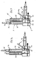
- the control device 6 is preferably designed as a rotary valve control, as shown in FIG. 4.
- a control block 6a with connecting lines 6b a rod-shaped rotary valve 6c is inserted, on its circumference connecting channels 6c 'for connecting and disconnecting the lines 6b are formed.
- the rod-shaped rotary valve 6 c is covered by a cover 6 d with a corresponding semicircular groove held by means of screws with the control block 6a connected is.
- a U-shaped component (Figure 4e) is on the control block 6a mounted in the connection holes 6e 'are formed for connecting lines through which Aspirated medium and discharged again after the pumping.
- a control bracket 6f fixed with a fork at the free end, which passes through a recess 6d 'in the cover 6d protrudes (Fig. 4a and 4c).
- This control bar 6f protrudes through an opening the base plate 1 and is connected to a pin 9e of a U-shaped reversing bracket 9 in Intervention, which will be explained in more detail with reference to FIGS. 2 and 3.
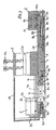
- the two piston slides 5 and 5 ' are provided with a clamping jaw 5c and 5c', respectively. provided, which projects through an opening 1a of the base plate 1 and with a metal band. 7 is firmly connected, which is guided around two spaced rollers in the form of rolling bearings 7a and 7a ' is, in a recess on the back of the base plate 1 in Rollenhaltem 7b, 7b 'stored are.
- the roll holder 7b is fixedly connected to the base plate 1 by a screw 7c, while the roll holder 7b 'by a screw 7c' relative to the base plate 1 in the longitudinal direction the metal band 7 is adjustable so that the belt 7 taut around the two rollers or rolling bearings 7a and 7a 'can be stretched.
- a metal strip 7 may also be a timing belt or the like can be provided.
- the jaw 5c 'of the piston carriage 5' not shown in FIG Section shown. It is at the in Fig. 2 upper strand of the two rollers 7a, 7a 'out Bandes 7 attached while the jaw 5 c is attached to the lower run of the belt 7.
- the clamping jaw 5c ' is provided with a blind bore 5d into which a drive dome 13 (FIG. 8) is inserted.
- a drive means engages the jaw 5c 'in the direction of the belt 7 back and forth reciprocated.
- the two piston slides 5 and 5 ' are reciprocated in opposite directions through the metal strip 7, whereby the one group of three pistons performs, for example, a pumping movement, while the other group of three pistons performs a suction movement.
- the jaw 5c ' engages in a slot 8a of a connecting rod 8, which on the back the base plate 1 is guided in a recess and with the opposite end with a slider 8b is fixed, which is displaceably guided on a guide rod 8c, which is fixedly arranged in a recess of the base plate 1.
- a Slider 8d With the slider 8b is a Slider 8d firmly connected, which at the two ends a bifurcated section with a Inclined surface 8e, which cooperates with a spring-loaded catch 10 or 10a, that during the sliding movement of the slider 8d in Fig. 3 to the right, the latch 10a pushed back and the leg 9a of the reverser bracket 9 is released, the by a Spring 9c 'is biased in the direction to the right.
- control bar 9 moves to the right under entrainment the control bar 6f, which engages with the pin 9e of the reversing bracket 9.
- the rotary valve 6c is rotated by relaxing the spring 9c 'in a position in which is switched from suction to conveying or vice versa.
- the left leg 9b of the reversing bow 9 in FIGS. 2 and 3 acts with a limit switch 16 preferably in the form of an inductive pickup together, the two positions 16a and 16b of the leg 9b notes.
- Via electrical lines 16c, 16c ' is a corresponding Signal to a drive motor 13 f (Fig. 8) forwarded so that this direction of rotation reverses to drive movement over the drive mandrel 13 engaging the jaw 5c ' of the piston slide 5 'in the figures to the left while at the same time the metal strip 7 of the piston slide 5 is moved to the right to perform a Pumphub.
- the jaw 5 c 'in Fig. 2 and 3 is first moved to the left without the Connecting rod 8 is taken, because the jaw 5 c 'in the slot 8 a of Connecting rod 8 moves.
- the connecting rod 8 in Fig. 2 and 3 moved to the left becomes.
- Fig. 5 and 5a show schematically with the reference numerals used in Figs. 2 and 3 the Reversing device with the control device. Due to the reproduced embodiment results a switching time of 2 ms on the rotary valve 6c, at the same time the direction of rotation of Drive motor 13f is switched over the inductive pickup 16.
- the inclined surfaces 8e formed directly on the connecting rod 8. In the slot 8a and the drive dome 13 can intervene to the Um Kunststoff ceremonies directly trigger.
- Fig. 6 shows schematically the suction and pressure stroke of the connected to the piston carriage Piston of two syringes 3 and 3 'in conjunction with the control device 6 and the rotary valve 6c.
- a shut-off vent rotary valve is shown in Fig. 6, whose Function will be explained in more detail with reference to FIG. 7.
- Fig. 6 the vent rotary valve 11 is shown in its closed position.
- Fig. 4 shows, the venting rotary valve 11 in the same manner as the control rotary valve 6c integrated into the control device 6. He juts over one end of the controller 6 before and is connected to a lever 11 a, so that it can be converted by hand.
- a bleed syringe 12 to a connecting line 11b of the control device 6 connected, in which the venting rotary valve 11 is arranged.
- This connection cable 11b is connected to the leads 6b leading to the syringe barrels 3c, in which schematic representation of FIGS. 6 and 7 only one of the leading to the lines 6b Connecting lines 11b is shown.
- the individual are successively Piston of the syringe 3 in the vertical position of the metering pump of FIG. 1 at the top of the Pulled out syringe barrel, as shown in FIG. 7 shows schematically.
- the venting syringe 12 is connected by switching the venting rotary valve 11, while the rotary valve 6c connects the outlet of the syringe 3 with the delivery side.
- the rotary valve 6c connects the outlet of the syringe 3 with the delivery side.
- medium is pressed into the syringe 3 through the venting syringe, with filled syringe 3 at its upper open end by the surface tension of the medium forms a dome M.
- the described metering pump operates by the drive motor 13f described below pulsation-free and continuous and can be used for a wide range of media up to 10 bar be used, the respective medium is transported gently.
- Flow rates are promoted, for example, within an hour a stroke of only about 2/10 mm can be performed.
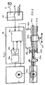
- Fig. 8 shows a play-free Driving the engaging in the dargestellen embodiment in the jaw 5c ' Drive dome 13.
- the drive motor generates a drive movement corresponding to a harmonic sinusoid. This contributes significantly to the generation of a pulsation-free promotion.
- play-free and rigid drive train with a play-free and torsionally stiff coupling 13e, one backlash-free and rigid bearing 13d, a gradient-stable and kink-resistant drive spindle 13c, a play-free spindle nut 13a and a play-free spindle nut guide 13b (Fig. 8).
- the achievable flow of the metering pump results from the piston area of the respective Spraying 3 and the conveying speed of the piston, with delivery volumes in the range from 80 n1 / h to 101 / h are achievable.
- the described metering pump with three syringes per delivery or suction stroke can take up to three Pump or mix different fluids in a definable ratio. Even if the Metering pump is designed for small flow rates, with a larger flow rate through Increasing the conveying speed of the piston rinsing by means of another medium be performed.
- Fig. 8 shows schematically the electrical or electronic control of the metering pump described with a motor electronics 14, a power stage 14a, a controller 14b and a Control unit 14 c, which receives the signals from the non-contact end position sensor 16 receives and for switching the direction of rotation to the motor 13f knower concerns.
- a Operating mode selector reproduced that a control or setpoint via a Potentiometer P, an analog signal A or via an interface RS allows, through the one Control via a PC or a corresponding software is possible.
- By software is a free parameterization of the flow and the flow rate possible.
- the drive unit shown schematically in FIG. 8 can be in a separate, block-shaped Be housed component from which only the drive pin 13 protrudes, with the Dosing pump is coupled.
- Dosing pump clamping jig or the like connecting elements can be provided preferably in conjunction with dowel pins between pump and drive unit, so that the Drive unit occupies a predetermined position relative to the metering pump.
- the dosing pump itself is constructed so that it can be sterilized in a few simple steps Cleaning can be disassembled.
- the clamping device 2 and the control device 6 be secured by screws to the base plate 1.
- the metering pump is expediently mounted on an L-shaped carrier T. mounted, wherein the metering pump is inserted between two support plates Tp. Side to one the support plates are the mode selector switch 15 and a knob 20 for adjustment the piston speed and the like provided.
- the in the dimensions relatively small Dosing pump can be positioned by means of the carrier T on a laboratory bench or the like become.
- the drive unit can in this case with the base plate 1 fixed between the carrier plates Tp be mounted while the medium-carrying control device 6, for example by means of Removable screws, so that all fluid-carrying components for cleaning and Sterilization can be quickly removed.
- the syringes not shown in FIG Be via unillustrated lines and connection plugs with the appropriate Holes in the control device 6 connected. On the front side of the control device 6 holes are provided for the connection lines.
- three pistons each are connected to a precisely working, play-free linear drive system coupled, with all the pistons synchronized move without a stroke difference between the individual pistons occurs. It can commercially available syringes in the diameter range of about 0.7 to 23 mm are used.
- all components of the metering pump coming into contact with the medium are off electrically insulating material or electrically insulated, so no electrical Potential of the medium can be derived, for example, if promoted ionized medium becomes.
Landscapes
- Engineering & Computer Science (AREA)
- Mechanical Engineering (AREA)
- General Engineering & Computer Science (AREA)
- Infusion, Injection, And Reservoir Apparatuses (AREA)
- Reciprocating Pumps (AREA)
- Automatic Analysis And Handling Materials Therefor (AREA)
Applications Claiming Priority (2)
| Application Number | Priority Date | Filing Date | Title |
|---|---|---|---|
| DE10346341A DE10346341A1 (de) | 2003-10-06 | 2003-10-06 | Dosierspritzenpumpe |
| DE10346341 | 2003-10-06 |
Publications (2)
| Publication Number | Publication Date |
|---|---|
| EP1522727A2 true EP1522727A2 (fr) | 2005-04-13 |
| EP1522727A3 EP1522727A3 (fr) | 2009-04-08 |
Family
ID=34306286
Family Applications (1)
| Application Number | Title | Priority Date | Filing Date |
|---|---|---|---|
| EP04023691A Withdrawn EP1522727A3 (fr) | 2003-10-06 | 2004-10-05 | Pompe de dosage |
Country Status (3)
| Country | Link |
|---|---|
| US (1) | US20050106051A1 (fr) |
| EP (1) | EP1522727A3 (fr) |
| DE (1) | DE10346341A1 (fr) |
Families Citing this family (1)
| Publication number | Priority date | Publication date | Assignee | Title |
|---|---|---|---|---|
| WO2013163033A1 (fr) * | 2012-04-23 | 2013-10-31 | Siemens Healthcare Diagnostics Inc. | Appareil de pompe à chambres multiples, systèmes et procédés |
Family Cites Families (20)
| Publication number | Priority date | Publication date | Assignee | Title |
|---|---|---|---|---|
| US1966498A (en) * | 1933-05-04 | 1934-07-17 | Gross Louis | Fluid measuring and dispensing apparatus |
| US1996498A (en) * | 1934-06-18 | 1935-04-02 | Young Radiator Co | Heat transfer device |
| DE1814237A1 (de) * | 1968-12-12 | 1970-06-25 | Lissem Peter | Geraet zur chemischen Untersuchung von Fluessigkeiten |
| US3554673A (en) * | 1969-01-31 | 1971-01-12 | Sage Instr Inc | Syringe pump |
| US4065230A (en) * | 1975-01-17 | 1977-12-27 | Hart Associates, Inc. | Reciprocating infusion pump and directional adapter set for use therewith |
| US4120202A (en) * | 1977-03-15 | 1978-10-17 | Baxter Travenol Laboratories, Inc. | Positive displacement pump |
| US4196730A (en) * | 1977-08-01 | 1980-04-08 | Wilson Dennis R | Liquid drug dispenser |
| US4288206A (en) * | 1979-08-15 | 1981-09-08 | Tigwell David C | Automatic multiple water sampler |
| US4470431A (en) * | 1982-02-23 | 1984-09-11 | American Hospital Supply Corporation | Syringe valve and clamping mechanism |
| US4652260A (en) * | 1985-03-11 | 1987-03-24 | Strato Medical Corporation | Infusion device |
| US4804368A (en) * | 1986-12-05 | 1989-02-14 | C. R. Bard, Inc. | Battery operated miniature syringe infusion pump and improved halfnut therefor |
| US4976696A (en) * | 1987-08-10 | 1990-12-11 | Becton, Dickinson And Company | Syringe pump and the like for delivering medication |
| DE3817411A1 (de) * | 1988-05-21 | 1989-11-30 | Fresenius Ag | Mehrfachinfusionssystem |
| US5176502A (en) * | 1990-04-25 | 1993-01-05 | Becton, Dickinson And Company | Syringe pump and the like for delivering medication |
| US5492535A (en) * | 1994-04-06 | 1996-02-20 | Cordis Corporation | Hand-powered pumping apparatus for perfusion and other fluid catheterization procedures |
| US5814015A (en) * | 1995-02-24 | 1998-09-29 | Harvard Clinical Technology, Inc. | Infusion pump for at least one syringe |
| EP1920718A1 (fr) * | 1995-04-20 | 2008-05-14 | ACIST Medical Systems, Inc. | Injecteur de produit de contraste radiographique |
| US6220487B1 (en) * | 1998-10-16 | 2001-04-24 | Micro Robotics Systems, Inc. | Dispensing apparatus |
| DE19933392A1 (de) * | 1999-07-21 | 2001-02-08 | Butsch Mietservice Gmbh | Dosiereinrichtung |
| DE10208776A1 (de) * | 2002-02-28 | 2003-09-04 | Muefa Ag | Infusionseinheit |
-
2003
- 2003-10-06 DE DE10346341A patent/DE10346341A1/de not_active Ceased
-
2004
- 2004-10-05 EP EP04023691A patent/EP1522727A3/fr not_active Withdrawn
- 2004-10-05 US US10/957,643 patent/US20050106051A1/en not_active Abandoned
Also Published As
| Publication number | Publication date |
|---|---|
| US20050106051A1 (en) | 2005-05-19 |
| DE10346341A1 (de) | 2005-05-12 |
| EP1522727A3 (fr) | 2009-04-08 |
Similar Documents
| Publication | Publication Date | Title |
|---|---|---|
| EP1495782B1 (fr) | Système de tatouage et de maquillage permanent | |
| DE2435912C2 (de) | Folge-Quetschventil | |
| DE68907028T2 (de) | Mikroschlaggeraet fuer markierung. | |
| DE1811153A1 (de) | Vorrichtung zum Einsetzen von Teilen in vorherbestimmte Positionen | |
| DE2809846A1 (de) | Abfuelleinrichtung fuer fluessiges gut | |
| EP1848287A1 (fr) | Dispositif de traitement d'un produit d'alimentation | |
| DE3513880A1 (de) | Geraet zum auspressen plastischer massen | |
| DE2556282C2 (de) | Vorrichtung zum gegensinnigen stufenlosen Verstellen zweier Dosierpumpenkolben | |
| EP0314994B1 (fr) | Dispositif de pompage avec double pompe | |
| EP0208827A1 (fr) | Pince | |
| DE10259565A1 (de) | Pendelhubstangenlager | |
| DE1598332A1 (de) | Gasspuergeraet | |
| DE4235860A1 (de) | Rohrweiche | |
| EP1522727A2 (fr) | Pompe de dosage | |
| EP1739434A2 (fr) | Dispositif de dosage à plusieurs canaux | |
| DE10059312A1 (de) | Zentriervorrichtung für Fördergut | |
| DE2146934B2 (de) | Elektromechanisches Hubgerät | |
| DE1528419C3 (de) | Flüssigkeitspumpe | |
| DE10191359B4 (de) | Medienpumpe | |
| DE1964263C3 (de) | Arretierbares Schrittschaltgetriebe | |
| DE8423316U1 (de) | Greifvorrichtung | |
| DE655928C (de) | Elektrische Widerstandsstumpfschweissmaschine, insbesondere Abbrennschweissmaschine | |
| DE2407964C3 (de) | Vorrichtung zum Einstellen des Kolbenhubes einer Kolbenpumpe | |
| DE202009014160U1 (de) | Schlitzdüsenvorrichtung | |
| EP0911615A1 (fr) | Appareil de dosage volumétrique |
Legal Events
| Date | Code | Title | Description |
|---|---|---|---|
| PUAI | Public reference made under article 153(3) epc to a published international application that has entered the european phase |
Free format text: ORIGINAL CODE: 0009012 |
|
| AK | Designated contracting states |
Kind code of ref document: A2 Designated state(s): AT BE BG CH CY CZ DE DK EE ES FI FR GB GR HU IE IT LI LU MC NL PL PT RO SE SI SK TR |
|
| AX | Request for extension of the european patent |
Extension state: AL HR LT LV MK |
|
| PUAL | Search report despatched |
Free format text: ORIGINAL CODE: 0009013 |
|
| AK | Designated contracting states |
Kind code of ref document: A3 Designated state(s): AT BE BG CH CY CZ DE DK EE ES FI FR GB GR HU IE IT LI LU MC NL PL PT RO SE SI SK TR |
|
| AX | Request for extension of the european patent |
Extension state: AL HR LT LV MK |
|
| AKX | Designation fees paid | ||
| STAA | Information on the status of an ep patent application or granted ep patent |
Free format text: STATUS: THE APPLICATION IS DEEMED TO BE WITHDRAWN |
|
| 18D | Application deemed to be withdrawn |
Effective date: 20091009 |
|
| REG | Reference to a national code |
Ref country code: DE Ref legal event code: 8566 |