EP1522734A1 - Verfahren zum Betreiben einer Hebeeinrichtung zum Abpumpen von verunreinigten flüssigen Medien, insbesondere Kühlschmiermittel - Google Patents
Verfahren zum Betreiben einer Hebeeinrichtung zum Abpumpen von verunreinigten flüssigen Medien, insbesondere Kühlschmiermittel Download PDFInfo
- Publication number
- EP1522734A1 EP1522734A1 EP04022303A EP04022303A EP1522734A1 EP 1522734 A1 EP1522734 A1 EP 1522734A1 EP 04022303 A EP04022303 A EP 04022303A EP 04022303 A EP04022303 A EP 04022303A EP 1522734 A1 EP1522734 A1 EP 1522734A1
- Authority
- EP
- European Patent Office
- Prior art keywords
- free
- centrifugal pump
- bypass
- impeller
- flow centrifugal
- Prior art date
- Legal status (The legal status is an assumption and is not a legal conclusion. Google has not performed a legal analysis and makes no representation as to the accuracy of the status listed.)
- Granted
Links
- 239000007788 liquid Substances 0.000 title claims abstract description 42
- 238000000034 method Methods 0.000 title claims abstract description 18
- 239000005068 cooling lubricant Substances 0.000 title claims description 29
- 238000005086 pumping Methods 0.000 claims abstract description 8
- 238000007789 sealing Methods 0.000 claims description 2
- 230000004888 barrier function Effects 0.000 claims 1
- 239000002826 coolant Substances 0.000 abstract description 10
- 238000011010 flushing procedure Methods 0.000 description 6
- 238000004140 cleaning Methods 0.000 description 3
- 238000013022 venting Methods 0.000 description 3
- 239000012535 impurity Substances 0.000 description 2
- 238000003754 machining Methods 0.000 description 2
- 238000004519 manufacturing process Methods 0.000 description 2
- 238000005299 abrasion Methods 0.000 description 1
- 230000015572 biosynthetic process Effects 0.000 description 1
- 238000004891 communication Methods 0.000 description 1
- 230000003750 conditioning effect Effects 0.000 description 1
- 230000000694 effects Effects 0.000 description 1
- 239000000839 emulsion Substances 0.000 description 1
- 239000012530 fluid Substances 0.000 description 1
- 238000005755 formation reaction Methods 0.000 description 1
- 238000009434 installation Methods 0.000 description 1
- 238000003801 milling Methods 0.000 description 1
- 239000000203 mixture Substances 0.000 description 1
- 239000003921 oil Substances 0.000 description 1
- 230000035699 permeability Effects 0.000 description 1
- 238000003860 storage Methods 0.000 description 1
- 239000000758 substrate Substances 0.000 description 1
Images


Classifications
-
- F—MECHANICAL ENGINEERING; LIGHTING; HEATING; WEAPONS; BLASTING
- F04—POSITIVE - DISPLACEMENT MACHINES FOR LIQUIDS; PUMPS FOR LIQUIDS OR ELASTIC FLUIDS
- F04D—NON-POSITIVE-DISPLACEMENT PUMPS
- F04D7/00—Pumps adapted for handling specific fluids, e.g. by selection of specific materials for pumps or pump parts
- F04D7/02—Pumps adapted for handling specific fluids, e.g. by selection of specific materials for pumps or pump parts of centrifugal type
- F04D7/04—Pumps adapted for handling specific fluids, e.g. by selection of specific materials for pumps or pump parts of centrifugal type the fluids being viscous or non-homogenous
-
- F—MECHANICAL ENGINEERING; LIGHTING; HEATING; WEAPONS; BLASTING
- F04—POSITIVE - DISPLACEMENT MACHINES FOR LIQUIDS; PUMPS FOR LIQUIDS OR ELASTIC FLUIDS
- F04D—NON-POSITIVE-DISPLACEMENT PUMPS
- F04D15/00—Control, e.g. regulation, of pumps, pumping installations or systems
- F04D15/0005—Control, e.g. regulation, of pumps, pumping installations or systems by using valves
- F04D15/0011—Control, e.g. regulation, of pumps, pumping installations or systems by using valves by-pass valves
-
- F—MECHANICAL ENGINEERING; LIGHTING; HEATING; WEAPONS; BLASTING
- F04—POSITIVE - DISPLACEMENT MACHINES FOR LIQUIDS; PUMPS FOR LIQUIDS OR ELASTIC FLUIDS
- F04D—NON-POSITIVE-DISPLACEMENT PUMPS
- F04D9/00—Priming; Preventing vapour lock
- F04D9/004—Priming of not self-priming pumps
- F04D9/005—Priming of not self-priming pumps by adducting or recycling liquid
-
- F—MECHANICAL ENGINEERING; LIGHTING; HEATING; WEAPONS; BLASTING
- F05—INDEXING SCHEMES RELATING TO ENGINES OR PUMPS IN VARIOUS SUBCLASSES OF CLASSES F01-F04
- F05D—INDEXING SCHEME FOR ASPECTS RELATING TO NON-POSITIVE-DISPLACEMENT MACHINES OR ENGINES, GAS-TURBINES OR JET-PROPULSION PLANTS
- F05D2260/00—Function
- F05D2260/60—Fluid transfer
- F05D2260/604—Vortex non-clogging type pumps
Definitions
- the present invention relates to a method for Operating a lifting device for pumping contaminated liquid media, in particular Cooling lubricant using at least one Free-flow centrifugal pump and a lifting device and a Free-flow centrifugal pump for carrying out the method.
- lifting devices and Free-rotating centrifugal pumps are available in a variety of forms and Execution known in the market and in use.
- such lifting devices are used with Free-flow centrifugal pumps and subsequent flushing channels used, in particular contaminated liquid media, arising from machine tools to collect, to collect in the lifting device and by means to pump off the free-stream centrifugal pump and a bspw.
- Cleaning device, filter device, Refurbishing device od. Like. Supply.
- the present invention is therefore the task underlying, a method, and a lifting device and a free-flow centrifugal pump for carrying out the method to create, with which on simple and cost-effective Way the aforementioned disadvantages can be eliminated, and in which a homogeneous suction of liquid contaminated media, in particular cooling lubricant is possible.
- an overall height, in particular Installation height of the lifting device at one time reduced minimum level in the lifting container be possible.
- the suction or a Intake area of the used in a lifting device Free-flow centrifugal pump in addition preferably via a Bypass with liquid medium, in particular cooling lubricant to supply.
- the bypass is preferably spaced and centrically in front of the suction opening of the pump housing the Free-flow centrifugal pump arranged and preferably leads permanently liquid medium the pump housing or the Impeller of the free-flow centrifugal pump too.
- the Reduce lifting device makes overall essential lower lifting devices with subsequent flushing channels can be produced.
- this can be the subsequent facilities, such as treatment facilities, Filter devices that contaminated liquid media, in particular contaminated liquid Clean coolant, operate more homogeneously. additionally can also be a storage container for providing cleaned liquid coolant much smaller train as a more homogeneous transport and to Providing cooling lubricant in this way is possible.
- the bypass outside and separately the Free-flow centrifugal pump is assigned.
- This one can For example, provided in a tub bottom of the lifting device be.
- the Free-flow centrifugal pump can bypass into a suction line be used, in all embodiments common is that an outlet opening of the bypass preferably centric to the suction or centric aligned with the impeller of the free-flow centrifugal pump is.
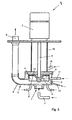
- Figure 1 1 has an inventive lifting device R to a free-flow centrifugal pump F 1 which projects into a lifting vessel 1 of the lifting device R.
- the free-flow centrifugal pump F 1 has a drive unit 2, in particular an electric motor, which drives an impeller 4 indicated by dashed lines via a drive shaft 3, which is only indicated here.
- the impeller 4 is seated in a pump housing 5, to which preferably centrally to the impeller 4 in a lower housing part 6, a suction port 7 connects.
- the free-flow centrifugal pump F 1 is inserted vertically in a lifting container 1, to which a flushing trough 9 connects.
- the lifting container 1 collects in the region of a trough 10, the mixture of cooling lubricant and impurities and is further pumped there for further processing, in particular for cleaning by means of the free-stream centrifugal pump F 1 through the outlet 8 and further transported.
- the outlet opening 12 is preferably aligned centrally to the suction port 7 or centrally and in a common axis to the impeller 4 of the free-flow centrifugal pump F 1 .
- the outlet opening 12 of the bypass 11 is also spaced apart in the impeller 4 and the suction port 7 of the free-flow centrifugal pump F 1 .
- bypass 11 cooling lubricant from the entire system of the free-flow centrifugal pump F 1 permanently supplied, wherein the supply under a pressure of about 0.2 bar to 3 bar, preferably 0.5 bar. Further, a delivery volume of about 5% to 15%, preferably 10% of the total delivery of the free-flow centrifugal pump F 1, the bypass 11 is supplied to displace sucked secondary air and to reduce a minimum level.
- a lifting device R 2 in which a free-flow centrifugal pump F 2 is arranged on a substrate 13 in a horizontal embodiment.
- a suction line 14 connects, which is in communication with the flushing trough 9.
- a bypass 11 adjoins the suction line 14 which supplies a partial flow of liquid medium, in particular cooling lubricant, to the suction opening 7 or the impeller 4 of the free-flow centrifugal pump F 2 in the manner described above.
- the outlet opening 12 and the bypass 11 is aligned centrally on the impeller 4 and lying in one axis, so that in this manner described above, liquid medium or cooling lubricant of the free-flow centrifugal pump F 2 can be permanently supplied to vent or an aspiration to reduce secondary air, wherein an efficiency of the free-flow centrifugal pump F 1 , in particular the lifting device R 2 is substantially improved.
- a free-flow centrifugal pump F 3 of conventional type is shown in which at least one or a plurality of bypasses 11 can be connected or connected at different locations in a pump housing 5, in particular in a lower housing part 6 in the manner described above to reduce secondary air during the aspiration of liquid medium or to vent the free-flow centrifugal pump F 3 .
- bypass 11 preferably centrally in front of the suction port 7 of the free-flow centrifugal pump F 3 can be assigned or opens directly into the lower housing part 6 of the pump housing 5, so that the outlet port 12 of the bypass 11 to the impeller. 4 the free-stream centrifugal pump F 3 is aligned.
- the bypass 11 in the pump housing 5 or housing part 6 axially, or radially or intervening axially to radially aligned with the impeller 4.
- the bypass 11 is arranged centrally and spaced from the intake opening 7.
Landscapes
- Engineering & Computer Science (AREA)
- Mechanical Engineering (AREA)
- General Engineering & Computer Science (AREA)
- Life Sciences & Earth Sciences (AREA)
- Sustainable Development (AREA)
- Structures Of Non-Positive Displacement Pumps (AREA)
- Jet Pumps And Other Pumps (AREA)
- Lubricants (AREA)
Abstract
Description
| Positionszahlenliste | |||||
| 1 | Hebebehälter | 34 | 67 | ||
| 2 | Antriebseinheit | 35 | 68 | ||
| 3 | Antriebswelle | 36 | 69 | ||
| 4 | Flügelrad | 37 | 70 | ||
| 5 | Pumpengehäuse | 38 | 71 | ||
| 6 | Gehäuseteil | 39 | 72 | ||
| 7 | Ansaugöffnung | 40 | 73 | ||
| 8 | Auslass | 41 | 74 | ||
| 9 | Spülrinne | 42 | 75 | ||
| 10 | Wannenboden | 43 | 76 | ||
| 11 | Bypass | 44 | 77 | ||
| 12 | Auslassöffnung | 45 | 78 | ||
| 13 | Untergrund | 46 | 79 | ||
| 14 | Saugleitung | 47 | |||
| 15 | Zwischengehäuse | 48 | R1 | Hebeeinrichtung | |
| 16 | Zuführleitung | 49 | R2 | Hebeeinrichtung | |
| 17 | 50 | ||||
| 18 | 51 | ||||
| 19 | 52 | F1 | Freistromkreiselpumpe | ||
| 20 | 53 | F2 | Freistromkreiselpumpe | ||
| 21 | 54 | F3 | Freistromkreiselpumpe | ||
| 22 | 55 | ||||
| 23 | 56 | ||||
| 24 | 57 | ||||
| 25 | 58 | ||||
| 26 | 59 | ||||
| 27 | 60 | ||||
| 28 | 61 | ||||
| 29 | 62 | ||||
| 30 | 63 | ||||
| 31 | 64 | ||||
| 32 | 65 | ||||
| 33 | 66 |
Claims (22)
- Verfahren zum Betreiben einer Hebeeinrichtung (R1, R2) zum Abpumpen von verunreinigten flüssigen Medien, insbesondere Kühlschmiermittel unter Verwendung zumindest einer Freistromkreiselpumpe (F1, F2, F3),
dadurch gekennzeichnet, dass eine Ansaugöffnung (7) oder ein Ansaugbereich der Freistromkreiselpumpe (F1, F2, F3) permanent mit einem flüssigen Medium beaufschlagt wird. - Verfahren nach Anspruch 1, dadurch gekennzeichnet, dass das flüssige Medium, insbesondere das Kühlschmiermittel, über einen Bypass (11) die Ansaugöffnung (7) oder den Ansaugbereich, insbesondere den Bereich des Flügelrades (4) der Freistromkreiselpumpe (F1, F2, F3) anströmt.
- Verfahren nach Anspruch 1 oder 2, dadurch gekennzeichnet, dass eine Auslassöffnung (12) des Bypasses (11) zu einer Ansaugöffnung (7) beabstandet angeordnet wird, so dass ein Teil des flüssigen Mediums, insbesondere ein Teil des Kühlschmiermittels permanent das Flügelrad (4) der Freistromkreiselpumpe (F1, F2, F3) beaufschlagt bzw. anströmt.
- Verfahren nach Anspruch 2 oder 3, dadurch gekennzeichnet, dass der Bypass (11) in einem Gehäuseteil (6) der Freistromkreiselpumpe (F1, F2, F3) nahe des Flügelrades (4) einmündet.
- Verfahren nach wenigstens einem der Ansprüche 1 bis 4, dadurch gekennzeichnet, dass in etwa 5% bis 15%, vorzugsweise 10% des Fördervolumens der Freistromkreiselpumpe (F1, F2, F3) über den Bypass (11) auf das Flügelrad (4) zugeführt werden.
- Verfahren nach wenigstens einem der Ansprüche 2 bis 5, dadurch gekennzeichnet, dass das flüssige Medium, insbesondere das Kühlschmiermittel mit etwa 0,2 bar bis 3 bar, insbesondere 0,5 bar Druck aus dem Bypass (11) auf das Flügelrad (4), die Ansaugöffnung (7) oder den Ansaugbereich der Freistromkreiselpumpe (F1, F2, F3) beaufschlagt werden.
- Verfahren nach wenigstens einem der Ansprüche 2 bis 6, dadurch gekennzeichnet, dass der Bypass (11) mittig und beabstandet vor der Ansaugöffnung (7) angeordnet wird, und das flüssige Medium aus dem Bypass (11) in etwa lotrecht auf das Flügelrad (4) der Freistromkreiselpumpe (F1, F2, F3) beaufschlagt oder beschleunigt wird.
- Verfahren nach wenigstens einem der Ansprüche 2 bis 7, dadurch gekennzeichnet, dass der Bypass (11) bei einer senkrechten Anordnung der Freistromkreiselpumpe (F1, F3) in einem Wannenboden (10) der Hebeeinrichtung (R1, R2) und bei einer liegenden Anordnung der Freistromkreiselpumpe (F2) in eine Saugleitung (14) der Hebeeinrichtung (R1, R2) einmündet.
- Verfahren nach wenigstens einem der Ansprüche 1 bis 9, dadurch gekennzeichnet, dass antriebswellenseitig oberhalb des Flügelrades (4) bei Unterdruck in der Freistromkreiselpumpe (F1, F2, F3) Sperrflüssigkeit zusätzlich zugeführt wird.
- Hebeeinrichtung zum Abpumpen von verunreinigten flüssigen Medien, insbesondere Kühlschmiermittel mit zumindest einer Freistromkreiselpumpe (F1, F2, F3), dadurch gekennzeichnet, dass über zumindest einen Bypass (11) eine Ansaugöffnung (7) oder ein Ansaugbereich der Freistromkreiselpumpe (F1, F2, F3) mit flüssigem Medium, insbesondere Kühlschmiermittel beaufschlagbar ist.
- Hebeeinrichtung nach Anspruch 10, dadurch gekennzeichnet, dass der Bypass (11) in einem Gehäuseteil (6) der Freistromkreiselpumpe (F1, F2, F3) angeordnet ist, und eine Auslassöffnung (12) des Bypasses (11) auf das Flügelrad (4) der Freistromkreiselpumpe (F1, F2, F3) ausgerichtet ist.
- Hebeeinrichtung nach Anspruch 10 oder 11, dadurch gekennzeichnet, dass der Bypass (11) im Bereich eines Wannenbodens (10) vorgesehen ist, und auf Flügelrad (4) der Freistromkreiselpumpe (F1, F2, F3) ausgerichtet ist, wobei eine Auslassöffnung (12) des Bypasses (11) zur Ansaugöffnung (7) der Freistromkreiselpumpe (F1, F2, F3) beabstandet, insbesondere höhenverstellbar ist.
- Hebeeinrichtung nach wenigstens einem der Ansprüche 10 bis 12, dadurch gekennzeichnet, dass zumindest ein Bypass (11) an eine an den Ansaugbereich anschliessende Saugleitung (14) der Freistromkreiselpumpe (F2) bei einer liegenden Bauweise einmündet, wobei eine Auslassöffnung (12) des Bypasses (11) vorzugsweise mittig auf das Flügelrad (4) der Freistromkreiselpumpe (F2) ausgerichtet ist.
- Hebeeinrichtung nach wenigstens einem der Ansprüche 10 bis 13, dadurch gekennzeichnet, dass zumindest ein Bypass (11) in einem Gehäuseteil (6) nahe des Flügelrades (4) der Freistromkreiselpumpe (F1, F2, F3) anschliesst, und die Auslassöffnung (12) des Bypasses (11) auf das Flügelrad (4) axial bis radial ausgerichtet ist.
- Hebeeinrichtung nach wenigstens einem der Ansprüche 10 bis 14, dadurch gekennzeichnet, dass das flüssige Medium, insbesondere Kühlschmiermittel mit einem Druck von 0,2 bar bis 3 bar, insbesondere 1 bar, zuführbar ist.
- Hebeeinrichtung nach wenigstens einem der Ansprüche 10 bis 15, dadurch gekennzeichnet, dass durch den Bypass (11) ein Fördervolumen an flüssigem Medium, insbesondere Kühlschmiermittel, von etwa 5% bis 15%, insbesondere 10% des Fördervolumens der Freistromkreiselpumpe (F1, F2, F3) zuführbar ist.
- Hebeeinrichtung nach wenigstens einem der Ansprüche 10 bis 16, dadurch gekennzeichnet, dass der Freistromkreiselpumpe (F1, F2, F3) oberhalb des Flügelrades (4) eine Zuführleitung (16), die in ein Zwischengehäuse (15) einmündet, über welche Sperrflüssigkeit bei Unterdruckbetrieb zuführbar ist.
- Freistromkreiselpumpe zum Abpumpen von verunreinigten flüssigen Medien, insbesondere Kühlschmiermittel, mit einem Flügelrad (4) und einer Ansaugöffnung (7), dadurch gekennzeichnet, dass der Ansaugöffnung (7), dem Ansaugbereich oder dem Flügelrad (4) über zumindest einen Bypass (11) zusätzlich flüssiges Medium, insbesondere Kühlschmiermittel zuführbar ist.
- Freistromkreiselpumpe nach Anspruch 18, dadurch gekennzeichnet, dass der Bypass (11) in ein Gehäuseteil (6) einmündet und eine Auslassöffnung (12) des Bypasses (11) axial, radial, sowie axial bis radial auf ein Flügelrad (4) ausgerichtet ist.
- Freistromkreiselpumpe nach Anspruch 18 oder 19, dadurch gekennzeichnet, dass der Bypass (11) ausserhalb einer Ansaugöffnung (7), zu dieser beabstandet ausgerichtet ist, wobei eine Öffnung des Bypasses (11) in etwa lotrecht und zentrisch in einer Achse liegend auf das Flügelrad (4) axial ausgerichtet ist.
- Freistromkreiselpumpe nach wenigstens einem Ansprüche 18 bis 20, dadurch gekennzeichnet, dass über den Bypass (11) flüssiges Medium, insbesondere Kühlschmiermittel mit 0,2 bar bis 3 bar, insbesondere 1 bar Druck dem Flügelrad (4) zuführbar ist.
- Freistromkreiselpumpe nach wenigstens einem der Ansprüche 18 bis 21, dadurch gekennzeichnet, dass über den Bypass (11) in etwa 5% bis 15%, insbesondere 10% des Gesamtfördervolumens der Freistromkreiselpumpe (F1, F2, F3) dem Flügelrad (4) zuführbar sind.
Priority Applications (1)
| Application Number | Priority Date | Filing Date | Title |
|---|---|---|---|
| PL04022303T PL1522734T3 (pl) | 2003-10-08 | 2004-09-20 | Sposób eksploatacji zbiorczego urządzenia do odpompowania zanieczyszczonych ciekłych mediów, zwłaszcza cieczy chłodząco-smarującej |
Applications Claiming Priority (2)
| Application Number | Priority Date | Filing Date | Title |
|---|---|---|---|
| DE10347261A DE10347261A1 (de) | 2003-10-08 | 2003-10-08 | Verfahren zum Betreiben einer Hebeeinrichtung zum Abpumpen von verunreinigten flüssigen Medien, insbesondere Kühlschmiermitteln |
| DE10347261 | 2003-10-08 |
Publications (2)
| Publication Number | Publication Date |
|---|---|
| EP1522734A1 true EP1522734A1 (de) | 2005-04-13 |
| EP1522734B1 EP1522734B1 (de) | 2007-09-19 |
Family
ID=34306370
Family Applications (1)
| Application Number | Title | Priority Date | Filing Date |
|---|---|---|---|
| EP04022303A Expired - Lifetime EP1522734B1 (de) | 2003-10-08 | 2004-09-20 | Verfahren zum Betreiben einer Hebeeinrichtung zum Abpumpen von verunreinigten flüssigen Medien, insbesondere Kühlschmiermittel |
Country Status (4)
| Country | Link |
|---|---|
| EP (1) | EP1522734B1 (de) |
| AT (1) | ATE373780T1 (de) |
| DE (2) | DE10347261A1 (de) |
| PL (1) | PL1522734T3 (de) |
Citations (5)
| Publication number | Priority date | Publication date | Assignee | Title |
|---|---|---|---|---|
| US4188172A (en) * | 1978-05-24 | 1980-02-12 | The United States Of America As Represented By The Secretary Of The Navy | Method and means for injecting hot liquid when pumping cold liquid |
| WO1988005132A1 (en) * | 1986-12-24 | 1988-07-14 | Eddy Pump Corporation | Improved pump construction |
| US5114312A (en) * | 1990-06-15 | 1992-05-19 | Atsco, Inc. | Slurry pump apparatus including fluid housing |
| EP0593005A1 (de) * | 1992-10-15 | 1994-04-20 | Scheible-Versorgungsanlagen Gmbh | Vorrichtung zum Entsorgen von flüssigen Medien |
| DE19804907C1 (de) * | 1998-02-07 | 1999-07-15 | Brinkmann Pumpen K H Brinkmann | Kreiselpumpe mit entlüfteter Pumpenkammer |
Family Cites Families (4)
| Publication number | Priority date | Publication date | Assignee | Title |
|---|---|---|---|---|
| DE1034033B (de) * | 1956-01-05 | 1958-07-10 | Karl Wernert | Pumpenanlage mit einer oberhalb des Fluessigkeitsspiegels angeordneten Kreiselpumpe |
| FR1403881A (fr) * | 1964-05-15 | 1965-06-25 | Worthington | Pompe rotative équipée d'un dispositif d'alimentation forcée |
| DE19962729A1 (de) * | 1999-12-23 | 2001-07-05 | Grundfos As | Selbstansaugendes Pumpenaggregat |
| DE10118525B4 (de) * | 2001-04-14 | 2005-03-17 | Brinkmann Pumpen K.H. Brinkmann Gmbh & Co. Kg | Vorrichtung zum Absaugen von Kühlschmierstoff aus einem Sammelbecken |
-
2003
- 2003-10-08 DE DE10347261A patent/DE10347261A1/de not_active Withdrawn
-
2004
- 2004-09-20 PL PL04022303T patent/PL1522734T3/pl unknown
- 2004-09-20 AT AT04022303T patent/ATE373780T1/de active
- 2004-09-20 EP EP04022303A patent/EP1522734B1/de not_active Expired - Lifetime
- 2004-09-20 DE DE502004005002T patent/DE502004005002D1/de not_active Expired - Lifetime
Patent Citations (5)
| Publication number | Priority date | Publication date | Assignee | Title |
|---|---|---|---|---|
| US4188172A (en) * | 1978-05-24 | 1980-02-12 | The United States Of America As Represented By The Secretary Of The Navy | Method and means for injecting hot liquid when pumping cold liquid |
| WO1988005132A1 (en) * | 1986-12-24 | 1988-07-14 | Eddy Pump Corporation | Improved pump construction |
| US5114312A (en) * | 1990-06-15 | 1992-05-19 | Atsco, Inc. | Slurry pump apparatus including fluid housing |
| EP0593005A1 (de) * | 1992-10-15 | 1994-04-20 | Scheible-Versorgungsanlagen Gmbh | Vorrichtung zum Entsorgen von flüssigen Medien |
| DE19804907C1 (de) * | 1998-02-07 | 1999-07-15 | Brinkmann Pumpen K H Brinkmann | Kreiselpumpe mit entlüfteter Pumpenkammer |
Also Published As
| Publication number | Publication date |
|---|---|
| DE502004005002D1 (de) | 2007-10-31 |
| EP1522734B1 (de) | 2007-09-19 |
| ATE373780T1 (de) | 2007-10-15 |
| PL1522734T3 (pl) | 2008-02-29 |
| DE10347261A1 (de) | 2005-05-04 |
Similar Documents
| Publication | Publication Date | Title |
|---|---|---|
| DE19781894B4 (de) | Selbstansaugende Kreiselpumpe | |
| DE1811100C3 (de) | Dichtungsanordnung | |
| DE102014104172B4 (de) | Werkzeugmaschine mit Schneidfluidfiltriervorrichtung | |
| DE1803293C3 (de) | ||
| EP3115609A1 (de) | Selbstreinigende pumpe | |
| DE69119183T3 (de) | Kreiselpumpe mit Abdichtungsmitteln | |
| EP2054169A1 (de) | Reinigungsvorrichtung mit einer flutkammer | |
| DE3015211A1 (de) | Schutzeinrichtung fuer unterwassermotoren | |
| DE102010052656B4 (de) | Hydraulische mahlkugelzu- und abfuhr für rührwerkskugelmühlen | |
| DE69303447T2 (de) | Vakuumpumpgerät | |
| DE68928623T2 (de) | Filtrierungseinrichtung, die eine pumpe enthält | |
| EP0459107B1 (de) | Drehschiebervakuumpumpe und ihr Verfahren zur Ölversorgung | |
| DE68916807T2 (de) | Waagerechte abnehmbare pumpe für filtriersysteme. | |
| DE1804667A1 (de) | Vorrichtung zum Absaugen und Vermischen einer aus einer Fluessigkeit und Feststoffteilchen bestehenden Aufschwemmung,insbesondere fuer Strahllaepp- oder Nassstrahlvorrichtungen | |
| DE10341998A1 (de) | Vorrichtung und Verfahren zur Oberflächenbehandlung von Werkstücken in einem Kreislaufsystem | |
| EP1522734B1 (de) | Verfahren zum Betreiben einer Hebeeinrichtung zum Abpumpen von verunreinigten flüssigen Medien, insbesondere Kühlschmiermittel | |
| WO2011091809A1 (de) | Gartenpumpenanordnung | |
| DE19905435B4 (de) | Tauchpumpe | |
| DE3141080C2 (de) | "Selbstansaugende Kreiselpumpe" | |
| DE102005034341A1 (de) | Tauchmotorpumpe mit Kühlmantel | |
| DE29514402U1 (de) | Vorrichtung zum Verbessern des Ansaugverhaltens von Strömungsförderpumpen | |
| DE490265C (de) | Einrichtung an Kreisel- und Kolbenpumpen zur Foerderung grob verunreinigter Fluessigkeiten | |
| EP3945218A1 (de) | Kreiselpumpe | |
| DE102017119019A1 (de) | Verfahren zum Behandeln einer spänebelasteten Flüssigkeit | |
| DE10296521B4 (de) | Pumpvorrichtung |
Legal Events
| Date | Code | Title | Description |
|---|---|---|---|
| PUAI | Public reference made under article 153(3) epc to a published international application that has entered the european phase |
Free format text: ORIGINAL CODE: 0009012 |
|
| AK | Designated contracting states |
Kind code of ref document: A1 Designated state(s): AT BE BG CH CY CZ DE DK EE ES FI FR GB GR HU IE IT LI LU MC NL PL PT RO SE SI SK TR |
|
| AX | Request for extension of the european patent |
Extension state: AL HR LT LV MK |
|
| 17P | Request for examination filed |
Effective date: 20050429 |
|
| AKX | Designation fees paid |
Designated state(s): AT BE BG CH CY CZ DE DK EE ES FI FR GB GR HU IE IT LI LU MC NL PL PT RO SE SI SK TR |
|
| GRAP | Despatch of communication of intention to grant a patent |
Free format text: ORIGINAL CODE: EPIDOSNIGR1 |
|
| GRAS | Grant fee paid |
Free format text: ORIGINAL CODE: EPIDOSNIGR3 |
|
| GRAA | (expected) grant |
Free format text: ORIGINAL CODE: 0009210 |
|
| AK | Designated contracting states |
Kind code of ref document: B1 Designated state(s): AT BE BG CH CY CZ DE DK EE ES FI FR GB GR HU IE IT LI LU MC NL PL PT RO SE SI SK TR |
|
| REG | Reference to a national code |
Ref country code: GB Ref legal event code: FG4D Free format text: NOT ENGLISH |
|
| REG | Reference to a national code |
Ref country code: CH Ref legal event code: EP |
|
| REG | Reference to a national code |
Ref country code: CH Ref legal event code: NV Representative=s name: ARIE WUBBEN |
|
| REF | Corresponds to: |
Ref document number: 502004005002 Country of ref document: DE Date of ref document: 20071031 Kind code of ref document: P |
|
| REG | Reference to a national code |
Ref country code: IE Ref legal event code: FG4D Free format text: LANGUAGE OF EP DOCUMENT: GERMAN |
|
| REG | Reference to a national code |
Ref country code: SE Ref legal event code: TRGR |
|
| PG25 | Lapsed in a contracting state [announced via postgrant information from national office to epo] |
Ref country code: FI Free format text: LAPSE BECAUSE OF FAILURE TO SUBMIT A TRANSLATION OF THE DESCRIPTION OR TO PAY THE FEE WITHIN THE PRESCRIBED TIME-LIMIT Effective date: 20070919 |
|
| REG | Reference to a national code |
Ref country code: PL Ref legal event code: T3 |
|
| NLV1 | Nl: lapsed or annulled due to failure to fulfill the requirements of art. 29p and 29m of the patents act | ||
| ET | Fr: translation filed | ||
| BERE | Be: lapsed |
Owner name: BAR + CO.-ANLAGENTECHNIK G.M.B.H. Effective date: 20070930 |
|
| PG25 | Lapsed in a contracting state [announced via postgrant information from national office to epo] |
Ref country code: MC Free format text: LAPSE BECAUSE OF NON-PAYMENT OF DUE FEES Effective date: 20070930 Ref country code: GR Free format text: LAPSE BECAUSE OF FAILURE TO SUBMIT A TRANSLATION OF THE DESCRIPTION OR TO PAY THE FEE WITHIN THE PRESCRIBED TIME-LIMIT Effective date: 20071220 Ref country code: NL Free format text: LAPSE BECAUSE OF FAILURE TO SUBMIT A TRANSLATION OF THE DESCRIPTION OR TO PAY THE FEE WITHIN THE PRESCRIBED TIME-LIMIT Effective date: 20070919 Ref country code: ES Free format text: LAPSE BECAUSE OF FAILURE TO SUBMIT A TRANSLATION OF THE DESCRIPTION OR TO PAY THE FEE WITHIN THE PRESCRIBED TIME-LIMIT Effective date: 20071230 |
|
| REG | Reference to a national code |
Ref country code: IE Ref legal event code: FD4D |
|
| REG | Reference to a national code |
Ref country code: HU Ref legal event code: AG4A Ref document number: E002802 Country of ref document: HU |
|
| PG25 | Lapsed in a contracting state [announced via postgrant information from national office to epo] |
Ref country code: PT Free format text: LAPSE BECAUSE OF FAILURE TO SUBMIT A TRANSLATION OF THE DESCRIPTION OR TO PAY THE FEE WITHIN THE PRESCRIBED TIME-LIMIT Effective date: 20080219 Ref country code: GB Free format text: LAPSE BECAUSE OF FAILURE TO SUBMIT A TRANSLATION OF THE DESCRIPTION OR TO PAY THE FEE WITHIN THE PRESCRIBED TIME-LIMIT Effective date: 20070919 Ref country code: SK Free format text: LAPSE BECAUSE OF FAILURE TO SUBMIT A TRANSLATION OF THE DESCRIPTION OR TO PAY THE FEE WITHIN THE PRESCRIBED TIME-LIMIT Effective date: 20070919 |
|
| PG25 | Lapsed in a contracting state [announced via postgrant information from national office to epo] |
Ref country code: RO Free format text: LAPSE BECAUSE OF FAILURE TO SUBMIT A TRANSLATION OF THE DESCRIPTION OR TO PAY THE FEE WITHIN THE PRESCRIBED TIME-LIMIT Effective date: 20070919 |
|
| PLBE | No opposition filed within time limit |
Free format text: ORIGINAL CODE: 0009261 |
|
| STAA | Information on the status of an ep patent application or granted ep patent |
Free format text: STATUS: NO OPPOSITION FILED WITHIN TIME LIMIT |
|
| PG25 | Lapsed in a contracting state [announced via postgrant information from national office to epo] |
Ref country code: DK Free format text: LAPSE BECAUSE OF FAILURE TO SUBMIT A TRANSLATION OF THE DESCRIPTION OR TO PAY THE FEE WITHIN THE PRESCRIBED TIME-LIMIT Effective date: 20070919 |
|
| 26N | No opposition filed |
Effective date: 20080620 |
|
| PG25 | Lapsed in a contracting state [announced via postgrant information from national office to epo] |
Ref country code: BE Free format text: LAPSE BECAUSE OF NON-PAYMENT OF DUE FEES Effective date: 20070930 |
|
| PG25 | Lapsed in a contracting state [announced via postgrant information from national office to epo] |
Ref country code: IE Free format text: LAPSE BECAUSE OF FAILURE TO SUBMIT A TRANSLATION OF THE DESCRIPTION OR TO PAY THE FEE WITHIN THE PRESCRIBED TIME-LIMIT Effective date: 20070919 |
|
| PG25 | Lapsed in a contracting state [announced via postgrant information from national office to epo] |
Ref country code: EE Free format text: LAPSE BECAUSE OF FAILURE TO SUBMIT A TRANSLATION OF THE DESCRIPTION OR TO PAY THE FEE WITHIN THE PRESCRIBED TIME-LIMIT Effective date: 20070919 |
|
| PG25 | Lapsed in a contracting state [announced via postgrant information from national office to epo] |
Ref country code: SI Free format text: LAPSE BECAUSE OF FAILURE TO SUBMIT A TRANSLATION OF THE DESCRIPTION OR TO PAY THE FEE WITHIN THE PRESCRIBED TIME-LIMIT Effective date: 20070919 |
|
| PG25 | Lapsed in a contracting state [announced via postgrant information from national office to epo] |
Ref country code: CY Free format text: LAPSE BECAUSE OF FAILURE TO SUBMIT A TRANSLATION OF THE DESCRIPTION OR TO PAY THE FEE WITHIN THE PRESCRIBED TIME-LIMIT Effective date: 20070919 |
|
| PG25 | Lapsed in a contracting state [announced via postgrant information from national office to epo] |
Ref country code: LU Free format text: LAPSE BECAUSE OF NON-PAYMENT OF DUE FEES Effective date: 20070920 Ref country code: BG Free format text: LAPSE BECAUSE OF FAILURE TO SUBMIT A TRANSLATION OF THE DESCRIPTION OR TO PAY THE FEE WITHIN THE PRESCRIBED TIME-LIMIT Effective date: 20071219 |
|
| PG25 | Lapsed in a contracting state [announced via postgrant information from national office to epo] |
Ref country code: TR Free format text: LAPSE BECAUSE OF FAILURE TO SUBMIT A TRANSLATION OF THE DESCRIPTION OR TO PAY THE FEE WITHIN THE PRESCRIBED TIME-LIMIT Effective date: 20070919 |
|
| PGFP | Annual fee paid to national office [announced via postgrant information from national office to epo] |
Ref country code: AT Payment date: 20100923 Year of fee payment: 7 |
|
| PGFP | Annual fee paid to national office [announced via postgrant information from national office to epo] |
Ref country code: CH Payment date: 20101014 Year of fee payment: 7 Ref country code: HU Payment date: 20101022 Year of fee payment: 7 |
|
| PGFP | Annual fee paid to national office [announced via postgrant information from national office to epo] |
Ref country code: CZ Payment date: 20110913 Year of fee payment: 8 Ref country code: SE Payment date: 20110923 Year of fee payment: 8 Ref country code: PL Payment date: 20110823 Year of fee payment: 8 |
|
| REG | Reference to a national code |
Ref country code: CH Ref legal event code: PL |
|
| PG25 | Lapsed in a contracting state [announced via postgrant information from national office to epo] |
Ref country code: HU Free format text: LAPSE BECAUSE OF NON-PAYMENT OF DUE FEES Effective date: 20110921 Ref country code: LI Free format text: LAPSE BECAUSE OF NON-PAYMENT OF DUE FEES Effective date: 20110930 Ref country code: CH Free format text: LAPSE BECAUSE OF NON-PAYMENT OF DUE FEES Effective date: 20110930 |
|
| REG | Reference to a national code |
Ref country code: AT Ref legal event code: MM01 Ref document number: 373780 Country of ref document: AT Kind code of ref document: T Effective date: 20110920 |
|
| PGFP | Annual fee paid to national office [announced via postgrant information from national office to epo] |
Ref country code: IT Payment date: 20120924 Year of fee payment: 9 |
|
| PG25 | Lapsed in a contracting state [announced via postgrant information from national office to epo] |
Ref country code: AT Free format text: LAPSE BECAUSE OF NON-PAYMENT OF DUE FEES Effective date: 20110920 |
|
| PGFP | Annual fee paid to national office [announced via postgrant information from national office to epo] |
Ref country code: FR Payment date: 20121010 Year of fee payment: 9 |
|
| PG25 | Lapsed in a contracting state [announced via postgrant information from national office to epo] |
Ref country code: CZ Free format text: LAPSE BECAUSE OF NON-PAYMENT OF DUE FEES Effective date: 20120920 Ref country code: SE Free format text: LAPSE BECAUSE OF NON-PAYMENT OF DUE FEES Effective date: 20120921 |
|
| REG | Reference to a national code |
Ref country code: SE Ref legal event code: EUG |
|
| PG25 | Lapsed in a contracting state [announced via postgrant information from national office to epo] |
Ref country code: PL Free format text: LAPSE BECAUSE OF NON-PAYMENT OF DUE FEES Effective date: 20120920 |
|
| REG | Reference to a national code |
Ref country code: PL Ref legal event code: LAPE |
|
| REG | Reference to a national code |
Ref country code: FR Ref legal event code: ST Effective date: 20140530 |
|
| PG25 | Lapsed in a contracting state [announced via postgrant information from national office to epo] |
Ref country code: IT Free format text: LAPSE BECAUSE OF NON-PAYMENT OF DUE FEES Effective date: 20130920 Ref country code: FR Free format text: LAPSE BECAUSE OF NON-PAYMENT OF DUE FEES Effective date: 20130930 |
|
| REG | Reference to a national code |
Ref country code: DE Ref legal event code: R082 Ref document number: 502004005002 Country of ref document: DE Representative=s name: PATENTANWAELTE UND RECHTSANWALT DR. WEISS, ARA, DE Ref country code: DE Ref legal event code: R082 Ref document number: 502004005002 Country of ref document: DE Representative=s name: PATENTANWAELTE UND RECHTSANWALT WEISS, ARAT & , DE |
|
| PGFP | Annual fee paid to national office [announced via postgrant information from national office to epo] |
Ref country code: DE Payment date: 20161129 Year of fee payment: 13 |
|
| REG | Reference to a national code |
Ref country code: DE Ref legal event code: R119 Ref document number: 502004005002 Country of ref document: DE |
|
| PG25 | Lapsed in a contracting state [announced via postgrant information from national office to epo] |
Ref country code: DE Free format text: LAPSE BECAUSE OF NON-PAYMENT OF DUE FEES Effective date: 20180404 |