EP1522738A2 - Volute pour une pompe centrifuge - Google Patents
Volute pour une pompe centrifuge Download PDFInfo
- Publication number
- EP1522738A2 EP1522738A2 EP04104313A EP04104313A EP1522738A2 EP 1522738 A2 EP1522738 A2 EP 1522738A2 EP 04104313 A EP04104313 A EP 04104313A EP 04104313 A EP04104313 A EP 04104313A EP 1522738 A2 EP1522738 A2 EP 1522738A2
- Authority
- EP
- European Patent Office
- Prior art keywords
- housing part
- housing
- spiral
- section
- flow
- Prior art date
- Legal status (The legal status is an assumption and is not a legal conclusion. Google has not performed a legal analysis and makes no representation as to the accuracy of the status listed.)
- Granted
Links
Images


Classifications
-
- F—MECHANICAL ENGINEERING; LIGHTING; HEATING; WEAPONS; BLASTING
- F04—POSITIVE - DISPLACEMENT MACHINES FOR LIQUIDS; PUMPS FOR LIQUIDS OR ELASTIC FLUIDS
- F04D—NON-POSITIVE-DISPLACEMENT PUMPS
- F04D29/00—Details, component parts, or accessories
- F04D29/40—Casings; Connections of working fluid
- F04D29/42—Casings; Connections of working fluid for radial or helico-centrifugal pumps
- F04D29/44—Fluid-guiding means, e.g. diffusers
- F04D29/445—Fluid-guiding means, e.g. diffusers especially adapted for liquid pumps
Definitions
- the invention relates to a spiral housing for a Centrifugal pump and a use of the spiral housing.
- the invention is therefore based on the object Spiral housing for a centrifugal pump to create at a highest possible throughput of the flow medium one possible having small outer diameter. Furthermore, the should Spiral housing be designed so that the largest possible Efficiency of the centrifugal pump can be realized.
- the object underlying the invention will you rch a Spiral housing solved for a centrifugal pump, which in the middle Area of the flow spiral a flow cross-section whose ratio of length to width is in the range of 1.5 to 2 and its ratio of the first part height, measured between the farthest from the entrance of the Fluid removed and parallel to the longitudinal axis of the Entrance extending boundary of the flow cross-section and the intersection of the length and the width, the second Partial height, measured between the intersection of the length and the Width and the closest to the entrance of the flow medium lying and parallel to the longitudinal axis of the entrance extending boundary of the flow cross-section in the area from 0.25 to 1, the limit de s Flow cross-section and the impeller of the centrifugal pump on next lying further limitation of the flow cross-section at right angles to each other ⁇ .
- the spiral housing can be formed in one piece or multiple parts.
- the Flow spiral is usually divided into three parts, an entry area, a central area, and a Spill area.
- At the entry area usually need Roundings are provided so that the flow medium out the entry passes streamlined into the flow spiral.
- the exit area has curves, the one To facilitate transition to the exit from the volute casing.
- the middle area In between lies the middle area, where some Constructive parameters, however, are kept constant should.
- the flow cross section not continuously constant, but increases in size Direction to the exit of the spiral housing continuously. Below the length is the largest length of the Flow cross-section to be understood at every point of the Flow cross-section parallel to the longitudinal axis of the entrance of Flow medium can be measured.
- the width is at the point in split a first part height and a second part height.
- the Sum, formed from the first partial height and from the second Part height then returns to the width.
- Under the right Angle ⁇ is an angle of 90 ° technically meant. This means that due to manufacturing tolerances also those angles are understood to be over 90 ° or under 90 °. Small angular deviations should thus still by fall the term "right angle ⁇ ".
- a preferred embodiment of the invention is that the volute casing of a first housing part and a second housing part, wherein the first housing part the Limitation and the second housing part 2, the further limitation of the flow cross section. It is advantageous that the preparation of the spiral housing, for example by a Casting process can be done without lost cores.
- the Assembly of the first housing part and the second Housing part can be exemplified in a simple way by a screw connection or by gluing done.
- the first housing part bores on at its outer boundary, parallel to the longitudinal axis of the inlet of the flow medium run.
- the first housing part in advantageously with screw on the drive housing secure the centrifugal pump.
- a further embodiment of the invention is that the second housing part is limited outside circular and on the outside has a circumferential groove.
- the orbiting Groove can seal elements in a relatively simple manner, For example, a sealing ring to be fixed. Furthermore it is possible to introduce into the groove adhesives to the second housing part in a relatively simple manner with the first Housing part to connect.
- a further embodiment of the invention provides that the first housing part on its outside a contact point for has an electrical connection. She can, for example as a plug connection for an electrical contact be educated. It is advantageous that the electrical Power supply of the centrifugal pump in a simple way over the first housing part can be done, with the required Space can also be kept relatively small.
- the first housing part at its opposite the entrance Side on a circular opening, the inner diameter of the Outer diameter of the second housing part opposite is formed complementary.
- the complementary Training is to be understood that the second housing part in the first housing part can be fitted positively.
- the second housing part almost f mulend can be integrated into the first housing part, what about it leading to an additional saving of space.
- a further embodiment of the invention provides that the second housing part has a central opening for the impeller of Centrifugal pump designed as a bearing for the drive is.
- the central opening becomes circular trained and stiffened at their inner edges, so that with one end inserted into the central opening drive for the Impeller of the centrifugal pump fixed in the central opening and thus can be stored.
- a bearing can be omitted in an advantageous manner become.
- the second Housing part of a part of the drive housing is that housing too understand in which the electric drive for the impeller the centrifugal pump is arranged. It is advantageous that on a separate one-off production of the second housing part can be waived.
- the subject of the invention is the use of the spiral housing as a housing for a cooling water centrifugal pump in a motor vehicle. It is advantageous that the in a motor vehicle only very limited available Space can be used in an optimal way.
- Fig. 1a), b) shows the inside of the first housing part and the inside of the second housing part in plan view.
- Fig. 2a), b) shows the inside of the first housing part and of the second housing part in three-dimensional representation.
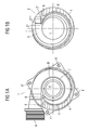
- Fig. 3 shows the first housing part and the second housing part three-dimensional in assembled condition.
- Fig. 4 shows the first housing part and the second housing part in assembled state in three-dimensional representation from another angle.
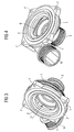
- Fig. 5 shows the view into the outlet of the spiral housing in three-dimensional shape.
- Fig. 6 shows the top view of the Spiralge housing with the middle range.
- FIG. 7 shows an enlarged view of the section D-D according to FIG. 6.
- Fig. 8a), b), c) shows the sections A-A, B-B and C-C of FIG. 6th
- Fig. 9 shows the first housing part in three-dimensional Presentation with the contact point.
- the first housing part 1 and in Fig. 1b) is the second housing part 2 in the plan view, respectively from the inside seen, represented.
- the first housing part 1 has a Inlet E of the flow medium and an outlet A of Fluid on. Furthermore, the first housing part 1 is on its outer side provided with holes 1 ', the Attachment to a drive housing (not shown) serve.
- the second housing part 2 has a central opening L for the impeller of the centrifugal pump (not shown). These If necessary, the central opening L can also be used as a bearing for the Drive be designed.
- the flow spiral has a beginning 2 * and one end 2 **.
- the flow medium which is usually a aqueous solution is star-shaped from the entrance E starting, so from the inside center against the outer Limitation of the flow spiral.
- the assembled state engages the second housing part 2 with its projecting tongue 2 'in the first housing part 1 such a, so that the first Edge a of the first housing part 1 at the second edge b of the second housing part 2 is present.
- the first stop surface c on the second stop surface d (each shown dotted) and the third stop surface e at the fourth abutment surface f (each with wavy lines shown).
- the area g of the first housing part. 1 the other hand, the second touches in the assembled state Housing part 2 of the spiral housing not.
- I'm in the assembled State of the spiral housing are the closest to the Inlet E of the flow medium lying and parallel to Longitudinal axis of the entrance E extending boundary j of Flow cross-section and the impeller of the centrifugal pump on nearest further limit h of Flow cross section at right angle ⁇ (not shown) to each other.
- the first housing part 1 forms the boundary j and the second housing part 2, the further limitation h of Flow cross-section.
- the further limitation h of Flow cross-section closes directly on a rümm th part i of the flow cross-section.
- the first housing part 1 and in Fig. 2b) is the second housing part 2, each three-dimensional and from the inside seen, represented.
- the second housing part 2 is outside circular limited and has on the outside a circumferential groove 2 ", in the example, a circumferential Seal can be introduced.
- Behind the end 2 ** of the Flow spiral in the direction of the outlet A for the Flow medium is no further limitation h of Flow cross-section realized at right angles ⁇ (not shown) to the limit j of Flow cross section is.
- the behind the end 2 ** in Direction to the outlet A of the Strömungsme medium extending Limitation of the flow cross section thus does not proceed planar, but is curved. This area represents the End region of the flow spiral.
- a similarly curved Limit (not shown) is also behind the beginning 2 * the flow spiral in the direction of the outlet A of the Flow medium in the so-called initial range recorded. Between the end area and this initial area is the middle area (not shown) for the continuous valid is that the boundary j to the limit h in the right Angle ⁇ (not shown) to each other.
- the spiral housing which consists of a first Housing part 1 and a second housing part 2 consists in assembled state shown in three dimensions.
- the first Housing part 1 is opposite the second housing part. 2 formed complementary, so that the second housing part 2 with his outer diameter in the first housing part 1 curse tend can be fitted. This will add an extra Required space requirement.
- the second housing part 2 is between the drive housing (not shown) and the first Housing part 1 of the spiral housing held positively, so that on additional fasteners for fixing the the first housing part 1 on the second housing part 2 is omitted can be.
- These measures also constitute a restriction possible of installation space.
- Fig. 4 the volute casing is in the assembled state as shown in FIG. 3 in three dimensions from another perspective shown.
- the spiral housing is very compact and requires due to its minimized outer diameter only a very limited space.
- FIG. 5 the spiral housing, consisting of the first housing part 1 and the second housing part 2 is shown three-dimensionally looking into the outlet A of the flow medium.
- the illustration illustrates the compact design of the spiral housing.
- FIG. 6 shows the top view of the spiral housing with a view of the first housing part 1.
- the approximate center area M of the flow spiral is highlighted by the dashed arrow.
- this middle region M can vary in size.
- the boundary j (not shown) and the further boundary h (not shown) of the flow cross-section are at right angles ⁇ (not shown) to one another.
- Fig. 7 the spiral housing in the section D -D of FIG. 6th shown. It is thus a cut through the middle area (not shown).
- the flow spiral has a flow cross section whose ratio of Length X to width Y is in the range of 1.5 to 2.
- the Ratio of the first partial height Y1 measured between the am farthest away from the inlet E of the flow medium and parallel to the longitudinal axis of the entrance E extending boundary the flow cross-section and the intersection point P of length X.
- the first housing part 1 form the Limit j and the second housing part the further limitation h of the flow cross-section.
- the flow space S of Flow spiral is shown hatched.
- the width of the protruding tongue (not shown) of the second housing part 2 corresponds to the constant flow width K of Inlet opening in the flow space S of the flow spiral.
- the flow width K over the entire range of Flow spiral in a particularly advantageous manner constant.
- Fig. 8a is the section A-A shown in FIG. 6.
- Fig. 8b is the section B-B shown in FIG. 6.
- Fig. 8c is the section C-C shown in FIG. 6.
- section A-A is a Section through the flow spiral, which is the beginning of the Flow spiral, thus not the middle area (not represented). This initial area of the Flow spiral is just behind the beginning (not shown) of the flow spiral and has an impeller the centrifugal pump (not shown) lying on the next ten curved boundary.
- a limitation j Flow cross section and a further limit h of Flow cross-section, the ⁇ at right angles to each other are thus not realized.
- Fig. 8a is the section A-A shown in FIG. 6.
- Fig. 8b is the section B-B shown in FIG. 6.
- Fig. 8c is the section C-C shown in FIG. 6.
- section A-A is a Section through the flow spiral, which is the beginning of the Flow spiral, thus not the middle area
- FIG. 8a) are the sections B-B shown in Figs. 8b) and c) or C-C in turn the middle area (not shown) assigned.
- the width and the first partial height and the second partial height with the representation of the intersection was shown in Fig. 8b), c) for reasons of Clarity omitted.
- FIG. 7 in FIG. 8b), c) the transition of the further boundary h in one curved part i of the flow cross section de utlich.
- the respective flow spaces S of the flow spiral are shown in FIG. 8a), b), c) again hatched.
- the first housing part 1 of the spiral housing three-dimensional view of the entrance E of Flow medium shown.
- the first housing part 1 indicates its outside a contact point 3 for an electrical Connection to.
- this contact point 3 as a kind Plug connection designed for electrical contacting is, the drive (not shown t) of the centrifugal pump (not shown) supplied with electrical energy. It is but also possible, via the contact point 3 corresponding control signals of the centrifugal pump supply. Due to the relatively small outer diameter d it first housing part 1 of the spiral housing, it is special advantageous possible, the contact point 3 as close to the To arrange inlet E of the flow medium, so that the Requires additional space to reduce.
Landscapes
- Engineering & Computer Science (AREA)
- Mechanical Engineering (AREA)
- General Engineering & Computer Science (AREA)
- Structures Of Non-Positive Displacement Pumps (AREA)
Applications Claiming Priority (2)
| Application Number | Priority Date | Filing Date | Title |
|---|---|---|---|
| DE10347302 | 2003-10-08 | ||
| DE2003147302 DE10347302A1 (de) | 2003-10-08 | 2003-10-08 | Spiralgehäuse für eine Kreiselpumpe |
Publications (3)
| Publication Number | Publication Date |
|---|---|
| EP1522738A2 true EP1522738A2 (fr) | 2005-04-13 |
| EP1522738A3 EP1522738A3 (fr) | 2010-01-20 |
| EP1522738B1 EP1522738B1 (fr) | 2013-12-25 |
Family
ID=34306373
Family Applications (1)
| Application Number | Title | Priority Date | Filing Date |
|---|---|---|---|
| EP20040104313 Revoked EP1522738B1 (fr) | 2003-10-08 | 2004-09-08 | Volute pour une pompe centrifuge |
Country Status (2)
| Country | Link |
|---|---|
| EP (1) | EP1522738B1 (fr) |
| DE (1) | DE10347302A1 (fr) |
Cited By (2)
| Publication number | Priority date | Publication date | Assignee | Title |
|---|---|---|---|---|
| EP2610502A4 (fr) * | 2010-12-28 | 2018-01-17 | Mitsubishi Heavy Industries, Ltd. | Structure de spirale de compresseur centrifuge |
| US11988218B2 (en) | 2021-03-10 | 2024-05-21 | Multi Parts Supply Usa, Inc. | Electric coolant pump with expansion compensating seal |
Families Citing this family (6)
| Publication number | Priority date | Publication date | Assignee | Title |
|---|---|---|---|---|
| DE102007010051A1 (de) | 2007-03-01 | 2008-09-04 | Continental Automotive Gmbh | Kreiselpumpe mit einem Spiralgehäuse |
| DE102007010050A1 (de) | 2007-03-01 | 2008-09-04 | Continental Automotive Gmbh | Kreiselpumpe mit einem Spiralgehäuse |
| DE102007036239A1 (de) | 2007-08-02 | 2009-02-05 | Continental Automotive Gmbh | Verfahren zur Abfuhr von Wärme von Bauteilen einer Flüssigkeitspumpe |
| DE102007036238A1 (de) | 2007-08-02 | 2009-02-05 | Continental Automotive Gmbh | Flüssigkeitspumpe |
| DE102007036240A1 (de) | 2007-08-02 | 2009-02-05 | Continental Automotive Gmbh | Flüssigkeitspumpe |
| DE102008019608A1 (de) | 2008-04-18 | 2009-10-22 | Continental Automotive Gmbh | Isolationsträger für einen Stator eines Elektromotors zum Antreiben von Flüssigkeitspumpen |
Citations (2)
| Publication number | Priority date | Publication date | Assignee | Title |
|---|---|---|---|---|
| DE1628361A1 (de) | 1966-02-02 | 1971-08-19 | Rotron Mfg Co | Zentrifugalgeblaese |
| DE19956380C1 (de) | 1999-11-24 | 2001-01-04 | Bosch Gmbh Robert | Flüssigkeitspumpe mit einem Motorgehäuse und Verfahren zur Herstellung eines Motorgehäuses |
Family Cites Families (4)
| Publication number | Priority date | Publication date | Assignee | Title |
|---|---|---|---|---|
| DE2206398A1 (de) * | 1972-02-11 | 1973-08-23 | Hanning Elektro Werke | Pumpenaggregat fuer umwaelzanlagen |
| GB2172659A (en) * | 1985-03-19 | 1986-09-24 | Austin Rover Group | Cooling liquid pump for internal combustion engine |
| IT1234504B (it) * | 1989-08-18 | 1992-05-18 | Tiziano Carretta | Cassa statorica in lamiera metallica, particolarmente per pompe radiali centrifughe |
| DE19943577A1 (de) * | 1999-09-13 | 2001-03-15 | Wilo Gmbh | Pumpengehäuse mit integrierter Elektronik |
-
2003
- 2003-10-08 DE DE2003147302 patent/DE10347302A1/de not_active Withdrawn
-
2004
- 2004-09-08 EP EP20040104313 patent/EP1522738B1/fr not_active Revoked
Patent Citations (2)
| Publication number | Priority date | Publication date | Assignee | Title |
|---|---|---|---|---|
| DE1628361A1 (de) | 1966-02-02 | 1971-08-19 | Rotron Mfg Co | Zentrifugalgeblaese |
| DE19956380C1 (de) | 1999-11-24 | 2001-01-04 | Bosch Gmbh Robert | Flüssigkeitspumpe mit einem Motorgehäuse und Verfahren zur Herstellung eines Motorgehäuses |
Non-Patent Citations (2)
| Title |
|---|
| AUTOMOBILTECHNISCHEN FACHZEITSCHRIFT, 1 February 1995 (1995-02-01), pages 86 - 90 |
| VON CARL PFLEIDERER: "Hartwig Petermann", article "Strömungsmaschinen", pages: 339 - 343 |
Cited By (2)
| Publication number | Priority date | Publication date | Assignee | Title |
|---|---|---|---|---|
| EP2610502A4 (fr) * | 2010-12-28 | 2018-01-17 | Mitsubishi Heavy Industries, Ltd. | Structure de spirale de compresseur centrifuge |
| US11988218B2 (en) | 2021-03-10 | 2024-05-21 | Multi Parts Supply Usa, Inc. | Electric coolant pump with expansion compensating seal |
Also Published As
| Publication number | Publication date |
|---|---|
| DE10347302A1 (de) | 2005-05-12 |
| EP1522738B1 (fr) | 2013-12-25 |
| EP1522738A3 (fr) | 2010-01-20 |
Similar Documents
| Publication | Publication Date | Title |
|---|---|---|
| DE69113616T2 (de) | Seitenkanalpumpe. | |
| DE102015112884A1 (de) | Heizpumpe | |
| DE4428633C2 (de) | Peripheralpumpe zum Zuführen von Kraftstoff zu einem Fahrzeugmotor | |
| EP2112380A1 (fr) | Pompe centrifuge en plusieurs étages en construction en ligne | |
| WO2001071192A1 (fr) | Pompe d'alimentation | |
| DE69326495T2 (de) | Kraftstoffpumpe | |
| EP1522738A2 (fr) | Volute pour une pompe centrifuge | |
| DE3228038A1 (de) | Fluessigkeit/gas-abscheider | |
| WO1995025895A1 (fr) | Dispositif pour reduire le bruit de pompes centrifuges | |
| DE10024741B4 (de) | Seitenkanalpumpe | |
| DE3128372A1 (de) | "peripheralkanalpumpe" | |
| DE102005015821A1 (de) | Laufrad und Kraftstoffpumpe, die dieses verwendet | |
| EP0902192A2 (fr) | Pompe à carter en volute | |
| DE69414344T2 (de) | Seitenströmungspumpe | |
| DE10335109B4 (de) | Geräuscharme Seitenkanalpumpe | |
| DE10311068A1 (de) | Geräuscharme Flügelradpumpen | |
| DE2523298A1 (de) | Rotationsverdraengerpumpe bzw. -motor | |
| DE4041545A1 (de) | Kreiselpumpe | |
| EP1131560B1 (fr) | Pompe regenerative | |
| DE112006003397T5 (de) | Brennstoffzellenverdichtersystem | |
| DE4113831A1 (de) | Geteiltes laufrad | |
| EP2100041B1 (fr) | Pompe centrifuge motorisée | |
| EP0733808B1 (fr) | Pompe centrifuge | |
| DE19908143C2 (de) | Geschmiedetes Kreiselpumpengehäuse | |
| DE3108214A1 (de) | "kraftstoff-foerderpumpe mit zwei hintereinander geschalteten pumpenstufen" |
Legal Events
| Date | Code | Title | Description |
|---|---|---|---|
| PUAI | Public reference made under article 153(3) epc to a published international application that has entered the european phase |
Free format text: ORIGINAL CODE: 0009012 |
|
| AK | Designated contracting states |
Kind code of ref document: A2 Designated state(s): AT BE BG CH CY CZ DE DK EE ES FI FR GB GR HU IE IT LI LU MC NL PL PT RO SE SI SK TR |
|
| AX | Request for extension of the european patent |
Extension state: AL HR LT LV MK |
|
| RAP1 | Party data changed (applicant data changed or rights of an application transferred) |
Owner name: CONTINENTAL AUTOMOTIVE GMBH |
|
| PUAL | Search report despatched |
Free format text: ORIGINAL CODE: 0009013 |
|
| AK | Designated contracting states |
Kind code of ref document: A3 Designated state(s): AT BE BG CH CY CZ DE DK EE ES FI FR GB GR HU IE IT LI LU MC NL PL PT RO SE SI SK TR |
|
| AX | Request for extension of the european patent |
Extension state: AL HR LT LV MK |
|
| 17P | Request for examination filed |
Effective date: 20100720 |
|
| AKX | Designation fees paid |
Designated state(s): DE FR IT |
|
| 17Q | First examination report despatched |
Effective date: 20110321 |
|
| GRAP | Despatch of communication of intention to grant a patent |
Free format text: ORIGINAL CODE: EPIDOSNIGR1 |
|
| INTG | Intention to grant announced |
Effective date: 20130717 |
|
| GRAS | Grant fee paid |
Free format text: ORIGINAL CODE: EPIDOSNIGR3 |
|
| GRAA | (expected) grant |
Free format text: ORIGINAL CODE: 0009210 |
|
| AK | Designated contracting states |
Kind code of ref document: B1 Designated state(s): DE FR IT |
|
| REG | Reference to a national code |
Ref country code: DE Ref legal event code: R096 Ref document number: 502004014471 Country of ref document: DE Effective date: 20140213 |
|
| REG | Reference to a national code |
Ref country code: DE Ref legal event code: R026 Ref document number: 502004014471 Country of ref document: DE |
|
| PLBI | Opposition filed |
Free format text: ORIGINAL CODE: 0009260 |
|
| PLAX | Notice of opposition and request to file observation + time limit sent |
Free format text: ORIGINAL CODE: EPIDOSNOBS2 |
|
| 26 | Opposition filed |
Opponent name: PIERBURG PUMP TECHNOLOGY GMBH Effective date: 20140925 |
|
| REG | Reference to a national code |
Ref country code: DE Ref legal event code: R026 Ref document number: 502004014471 Country of ref document: DE Effective date: 20140925 |
|
| PLAF | Information modified related to communication of a notice of opposition and request to file observations + time limit |
Free format text: ORIGINAL CODE: EPIDOSCOBS2 |
|
| PLBB | Reply of patent proprietor to notice(s) of opposition received |
Free format text: ORIGINAL CODE: EPIDOSNOBS3 |
|
| REG | Reference to a national code |
Ref country code: FR Ref legal event code: ST Effective date: 20150529 |
|
| PG25 | Lapsed in a contracting state [announced via postgrant information from national office to epo] |
Ref country code: FR Free format text: LAPSE BECAUSE OF NON-PAYMENT OF DUE FEES Effective date: 20140930 |
|
| PG25 | Lapsed in a contracting state [announced via postgrant information from national office to epo] |
Ref country code: IT Free format text: LAPSE BECAUSE OF FAILURE TO SUBMIT A TRANSLATION OF THE DESCRIPTION OR TO PAY THE FEE WITHIN THE PRESCRIBED TIME-LIMIT Effective date: 20131225 |
|
| RDAF | Communication despatched that patent is revoked |
Free format text: ORIGINAL CODE: EPIDOSNREV1 |
|
| STAA | Information on the status of an ep patent application or granted ep patent |
Free format text: STATUS: THE PATENT HAS BEEN GRANTED |
|
| APBM | Appeal reference recorded |
Free format text: ORIGINAL CODE: EPIDOSNREFNO |
|
| APBP | Date of receipt of notice of appeal recorded |
Free format text: ORIGINAL CODE: EPIDOSNNOA2O |
|
| APAH | Appeal reference modified |
Free format text: ORIGINAL CODE: EPIDOSCREFNO |
|
| PGFP | Annual fee paid to national office [announced via postgrant information from national office to epo] |
Ref country code: DE Payment date: 20170930 Year of fee payment: 14 |
|
| APBU | Appeal procedure closed |
Free format text: ORIGINAL CODE: EPIDOSNNOA9O |
|
| REG | Reference to a national code |
Ref country code: DE Ref legal event code: R064 Ref document number: 502004014471 Country of ref document: DE Ref country code: DE Ref legal event code: R103 Ref document number: 502004014471 Country of ref document: DE |
|
| RDAG | Patent revoked |
Free format text: ORIGINAL CODE: 0009271 |
|
| STAA | Information on the status of an ep patent application or granted ep patent |
Free format text: STATUS: PATENT REVOKED |
|
| 27W | Patent revoked |
Effective date: 20180311 |