EP1522799B1 - Méthode et installation pour la climatisation d'une pièce - Google Patents
Méthode et installation pour la climatisation d'une pièce Download PDFInfo
- Publication number
- EP1522799B1 EP1522799B1 EP04022266.3A EP04022266A EP1522799B1 EP 1522799 B1 EP1522799 B1 EP 1522799B1 EP 04022266 A EP04022266 A EP 04022266A EP 1522799 B1 EP1522799 B1 EP 1522799B1
- Authority
- EP
- European Patent Office
- Prior art keywords
- air
- room
- loop control
- unit
- window
- Prior art date
- Legal status (The legal status is an assumption and is not a legal conclusion. Google has not performed a legal analysis and makes no representation as to the accuracy of the status listed.)
- Expired - Lifetime
Links
Images


Classifications
-
- F—MECHANICAL ENGINEERING; LIGHTING; HEATING; WEAPONS; BLASTING
- F24—HEATING; RANGES; VENTILATING
- F24F—AIR-CONDITIONING; AIR-HUMIDIFICATION; VENTILATION; USE OF AIR CURRENTS FOR SCREENING
- F24F1/00—Room units for air-conditioning, e.g. separate or self-contained units or units receiving primary air from a central station
- F24F1/01—Room units for air-conditioning, e.g. separate or self-contained units or units receiving primary air from a central station in which secondary air is induced by injector action of the primary air
-
- F—MECHANICAL ENGINEERING; LIGHTING; HEATING; WEAPONS; BLASTING
- F24—HEATING; RANGES; VENTILATING
- F24F—AIR-CONDITIONING; AIR-HUMIDIFICATION; VENTILATION; USE OF AIR CURRENTS FOR SCREENING
- F24F11/00—Control or safety arrangements
- F24F11/70—Control systems characterised by their outputs; Constructional details thereof
- F24F11/80—Control systems characterised by their outputs; Constructional details thereof for controlling the temperature of the supplied air
- F24F11/83—Control systems characterised by their outputs; Constructional details thereof for controlling the temperature of the supplied air by controlling the supply of heat-exchange fluids to heat-exchangers
- F24F11/84—Control systems characterised by their outputs; Constructional details thereof for controlling the temperature of the supplied air by controlling the supply of heat-exchange fluids to heat-exchangers using valves
-
- F—MECHANICAL ENGINEERING; LIGHTING; HEATING; WEAPONS; BLASTING
- F24—HEATING; RANGES; VENTILATING
- F24F—AIR-CONDITIONING; AIR-HUMIDIFICATION; VENTILATION; USE OF AIR CURRENTS FOR SCREENING
- F24F11/00—Control or safety arrangements
- F24F11/0001—Control or safety arrangements for ventilation
-
- F—MECHANICAL ENGINEERING; LIGHTING; HEATING; WEAPONS; BLASTING
- F24—HEATING; RANGES; VENTILATING
- F24F—AIR-CONDITIONING; AIR-HUMIDIFICATION; VENTILATION; USE OF AIR CURRENTS FOR SCREENING
- F24F13/00—Details common to, or for air-conditioning, air-humidification, ventilation or use of air currents for screening
- F24F13/08—Air-flow control members, e.g. louvres, grilles, flaps or guide plates
- F24F13/10—Air-flow control members, e.g. louvres, grilles, flaps or guide plates movable, e.g. dampers
- F24F13/14—Air-flow control members, e.g. louvres, grilles, flaps or guide plates movable, e.g. dampers built up of tilting members, e.g. louvre
- F24F13/1426—Air-flow control members, e.g. louvres, grilles, flaps or guide plates movable, e.g. dampers built up of tilting members, e.g. louvre characterised by actuating means
-
- F—MECHANICAL ENGINEERING; LIGHTING; HEATING; WEAPONS; BLASTING
- F24—HEATING; RANGES; VENTILATING
- F24F—AIR-CONDITIONING; AIR-HUMIDIFICATION; VENTILATION; USE OF AIR CURRENTS FOR SCREENING
- F24F11/00—Control or safety arrangements
- F24F11/70—Control systems characterised by their outputs; Constructional details thereof
- F24F11/72—Control systems characterised by their outputs; Constructional details thereof for controlling the supply of treated air, e.g. its pressure
- F24F11/74—Control systems characterised by their outputs; Constructional details thereof for controlling the supply of treated air, e.g. its pressure for controlling air flow rate or air velocity
-
- F—MECHANICAL ENGINEERING; LIGHTING; HEATING; WEAPONS; BLASTING
- F24—HEATING; RANGES; VENTILATING
- F24F—AIR-CONDITIONING; AIR-HUMIDIFICATION; VENTILATION; USE OF AIR CURRENTS FOR SCREENING
- F24F11/00—Control or safety arrangements
- F24F11/70—Control systems characterised by their outputs; Constructional details thereof
- F24F11/80—Control systems characterised by their outputs; Constructional details thereof for controlling the temperature of the supplied air
- F24F11/83—Control systems characterised by their outputs; Constructional details thereof for controlling the temperature of the supplied air by controlling the supply of heat-exchange fluids to heat-exchangers
-
- F—MECHANICAL ENGINEERING; LIGHTING; HEATING; WEAPONS; BLASTING
- F24—HEATING; RANGES; VENTILATING
- F24F—AIR-CONDITIONING; AIR-HUMIDIFICATION; VENTILATION; USE OF AIR CURRENTS FOR SCREENING
- F24F11/00—Control or safety arrangements
- F24F11/0001—Control or safety arrangements for ventilation
- F24F2011/0002—Control or safety arrangements for ventilation for admittance of outside air
-
- F—MECHANICAL ENGINEERING; LIGHTING; HEATING; WEAPONS; BLASTING
- F24—HEATING; RANGES; VENTILATING
- F24F—AIR-CONDITIONING; AIR-HUMIDIFICATION; VENTILATION; USE OF AIR CURRENTS FOR SCREENING
- F24F13/00—Details common to, or for air-conditioning, air-humidification, ventilation or use of air currents for screening
- F24F13/08—Air-flow control members, e.g. louvres, grilles, flaps or guide plates
- F24F13/10—Air-flow control members, e.g. louvres, grilles, flaps or guide plates movable, e.g. dampers
- F24F13/14—Air-flow control members, e.g. louvres, grilles, flaps or guide plates movable, e.g. dampers built up of tilting members, e.g. louvre
- F24F13/1426—Air-flow control members, e.g. louvres, grilles, flaps or guide plates movable, e.g. dampers built up of tilting members, e.g. louvre characterised by actuating means
- F24F2013/1433—Air-flow control members, e.g. louvres, grilles, flaps or guide plates movable, e.g. dampers built up of tilting members, e.g. louvre characterised by actuating means with electric motors
-
- F—MECHANICAL ENGINEERING; LIGHTING; HEATING; WEAPONS; BLASTING
- F24—HEATING; RANGES; VENTILATING
- F24F—AIR-CONDITIONING; AIR-HUMIDIFICATION; VENTILATION; USE OF AIR CURRENTS FOR SCREENING
- F24F2110/00—Control inputs relating to air properties
- F24F2110/10—Temperature
- F24F2110/12—Temperature of the outside air
-
- F—MECHANICAL ENGINEERING; LIGHTING; HEATING; WEAPONS; BLASTING
- F24—HEATING; RANGES; VENTILATING
- F24F—AIR-CONDITIONING; AIR-HUMIDIFICATION; VENTILATION; USE OF AIR CURRENTS FOR SCREENING
- F24F2110/00—Control inputs relating to air properties
- F24F2110/30—Velocity
- F24F2110/32—Velocity of the outside air
Definitions
- the invention relates to a method for air conditioning a room in which outside air can flow through a not connected to an air conditioner outside air opening into the room and room air is conditioned by means of at least one air conditioner.
- a method of the type mentioned above is carried out when a room of a building or the like is conditioned by means of an air conditioner and at the same time a window of the room is open.
- the open window may cause the room air temperature to rise, especially in summer. If a temperature sensor of the air conditioner is located in the room, the temperature increase is registered and the air conditioner attempts to lower the room air temperature again.
- the open window leads to a strong room air cooling, which tries to compensate for the air conditioner.
- the invention has for its object to provide a method for air conditioning of a room that ge Dunrteistette a sufficient proportion of fresh air in a room while optimizing the air conditioning of the room.
- a method in particular by the combined control or regulation of at least the following variables: outside air opening cross-section, and volume flow a heating and / or coolant through at least one heat exchanger of the air conditioner.
- the above-mentioned variables are adjusted continuously or in short time intervals by the combined control, that is to say coordinated with each other and taking into account the respective present situation, in such a way that optimum air-conditioning conditions result in the room.
- a correspondingly large set outside air opening cross-section ensures the influx of fresh air.
- the outside air temperature is taken into account in order to maintain or maintain the desired room air temperature in the room.
- the control or regulation of the air volume flow of the air conditioner leads to a correspondingly large volume flow treatment of the room air, which is conditioned in the recirculation method. Since the air conditioner has a heat exchanger which can heat or cool the air volume flow of the room air to the desired extent by a correspondingly set volume flow of a heating or cooling medium, the desired room temperature is set. In the case of a so-called "silent cooling", the combined control or regulation of the outside air opening cross section and the volume flow of a heating and / or cooling medium, in particular coolant, by at least one heat exchanger of the air conditioner.
- the combined control or regulation always ensures that, for example, in the case of very low outside temperatures, the outside air opening cross-section is kept as small as possible in order to avoid an unpleasant room climate. Nevertheless, a sufficient oxygen content of the room air is guaranteed by the outside air supply.
- the cross section of the outside air opening is not kept permanently open, but only intermittently for the purpose a so-called shock ventilation ascended and then the outside air opening, in particular a window or the like, is closed again.
- the fan coil unit has as essential components a fan for conveying air and the already mentioned heat exchanger whose heating or cooling medium can be varied in the volume flow. If a speed influence of the fan is made, then the above-mentioned air volume flow can be adjusted thereby.
- an induction device is used as an air conditioner.
- the induction effect is achieved by sucking in air and air nozzles by means of an air conveyor, such as a fan.
- the air nozzles generate in a mixing chamber a negative pressure, is sucked through the more room air that passes through the mentioned heat exchanger.
- the volume flow of a heating or cooling medium of the heat exchanger can be influenced accordingly by means of the combined control or regulation.
- outside air can enter the room not only through the outside air opening cross section, but that the air conditioner, in particular the fan coil and / or the induction device also introduces outside air into the room.
- the fan coil the fan may, for example, convey room air, outside air or both room air and outside air and thereby condition the conveyed air flow by means of the heat exchanger.
- the induction device it is possible to supply the air nozzles with room air or outside air, or with both room air and outside air.
- Outside air can be supplied to the room via the already mentioned outside air opening cross-section through the outside air opening and / or an additional outside air access. Through the outside air opening the outside air always gets directly into the room, without them passing the air conditioner. Additionally or alternatively, it is possible, by an outside air access to the air conditioner, which may be configured as a fan coil and / or induction device to supply outside air. Additionally or alternatively, there is also the possibility that a certain proportion of the air flowing through the outside air opening into the room is sucked in and conditioned by the air conditioning unit. Another part of the outside air is distributed without passing through the air conditioner in the room.
- the air conditioner, the fan coil and / or the induction unit is supplied with centrally processed primary air.
- the centrally processed primary air is preferably outside air, which is processed centrally with regard to its parameters, in particular temperature and / or air humidity, and then supplied via appropriate air ducts to the air conditioning unit, the fan coil unit and / or the induction unit.
- at least a portion of the centrally processed primary air passes without passing through the air conditioner in the room to be air-conditioned. In such a case, the combined control will control the flow rate of this centrally treated primary air.
- the space is essentially conditioned by means of displacement ventilation.
- the space is air conditioned essentially by means of mixed source ventilation.
- the invention further relates to an arrangement for the air conditioning of a room in which outside air can flow through a not connected to an air conditioner outside air opening into the room and room air is conditioned by means of at least one air conditioner, wherein a control and / or regulating device for the combined control and / or regulation of at least the following sizes is provided: outside air opening cross-section and volume flow of a heating and / or coolant through at least one heat exchanger of the air conditioner.
- the air conditioner may in particular be a fan coil and / or an induction unit.
- the fan coil and / or the induction unit may be central or remote units. If they are central units, they are allocated in the room to be air-conditioned, but are supplied with centrally treated air.
- the central devices in the room are used for the aftertreatment of the treated air - in particular heating or cooling - or they mix in room air before the aftertreatment takes place.
- Decentralized devices are devices installed in the room. These devices are designed in particular for the volume of air and other requirements (temperature and / or humidity) of the room to be air conditioned.
- the outside air opening is formed by the cross section of a window associated with the room, a door or the like. through the combined control or regulation of the outside air opening cross section is adjusted accordingly.
- the window sash position can preferably be varied steplessly or in steps by means of a suitable drive device, in order to provide the required opening cross section for the inflow of outside air.
- the drive device is controlled by the combined control or regulation, so that a controllable or controllable drive device is present.
- the drive device may have an electric motor for adjusting the outside air opening cross section.
- the mentioned drive device or a separate device may include a locking device of the window, the door or the like for unlocking or locking the Press sash, the door leaf or the like.
- a locking device of the window, the door or the like for unlocking or locking the Press sash, the door leaf or the like.
- a lock it is initially provided that the outside air opening cross section is closed and then the window, the door or the like is locked. This unlocking or locking can be done in the case of a window, for example by means of a drive rod system that is driven by the drive device or the separate device. Manual intervention is therefore not required.
- control or regulating device may be assigned to the drive device.
- control or regulating device and the drive means are housed in a common housing.
- This combination of control or regulating device and the drive device is located in particular on the window, the door or the like, preferably on the window sash, on the door leaf or the like.
- window drive housing not only drive and control or regulation can be accommodated, but also sensors. These sensors are in particular air temperature sensors and / or air speed meters.
- the fan coil can be designed in particular as floor, parapet and / or ceiling unit.
- the induction device is a floor, parapet and / or ceiling device.
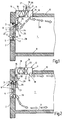
- FIG. 1 shows, in cross-section, a section of a room 1 to be conditioned of a building or the like.
- the room has a facade wall 2 with a window opening 3.
- a window 4 which has a fixed frame 5 and a movable sash 6.
- the window sash 6 can be pivoted about a lower, horizontal tilting axis 7 in order to set a corresponding outside air opening cross-section 8.
- the room 1 also has a bottom 9 and a ceiling 10.
- an air conditioner 11 is inserted in alignment.
- the air conditioner 11 is located immediately adjacent to the facade wall 2 and is designed as a fan coil 12. Due to its arrangement in the ceiling 10, the fan coil 12 forms a ceiling unit 13.
- the fan coil 12 has in the area near the window 4 an air inlet opening 14 and further away from the window 4- an air outlet opening 15. Between the air inlet opening 14 and the air outlet opening 15 is -in the interior of the fan coil 12- a fan 16 and downstream of the fan 16- a heat exchanger 17 is arranged. The speed of the fan 16 is adjustable, so that with him a corresponding air flow rate 18 is promoted. This air volume flow 18 enters through the air inlet opening 14 in the fan coil 12 and through the air outlet opening 15 back into the room 1.
- the heat exchanger 17 are associated with supply and discharge lines 19 for a centrally treated heating or cooling means, wherein the volume flow of the heating or cooling means by means of a Volumenstromeinstell 180 is adjustable.
- a drive device 21 for the actuation of the window sash 6 is attached on the window sash 6 of the window 4.
- the drive device 21 is connected via a force-effective path 22 with the frame 5.
- the drive device 21 acts on the force-effective section 22 and thereby spends the window sash 6 in the respective desired open position, so that adjusts a corresponding outside air opening cross-section 8.
- the drive means 21 has a locking device 23 which cooperates with a drive rod system of the window 4, not shown. In this way it is ensured that upon actuation of the drive device 21, first by means of the locking device 23, an unlocking of the window sash 6 takes place before it is spent in the open position. If the window sash 6 is closed, then the locking device 23 of the drive device 21 ensures that a lock is performed after closing the window sash 6.
- control or regulating device 25 In the housing 24 of the drive device 21 is also a control or regulating device 25, the -in dependence of certain parameters, the air conditioning of the room 1 controls or regulates. This will be discussed in more detail below.
- the control or regulating device can also be accommodated at a different location of the room 1.
- FIG. 1 works as follows: As can be seen, the window sash 6 has a certain open position, which allows the entry of outside air 26. Because in the FIG. 1 the summer case is shown, penetrates relatively warm outside air 26 in the upper region of the window 4 in the room 1 and passes to the air inlet opening 14 of the fan coil 12, promoted by the fan 16. This air passes through the heat exchanger 17 and is a cooling vortex- by a corresponding coolant 27, which flows through the heat exchanger 17, cooled. The cooled air passes through the air outlet opening 15 in the room 1 back. This conditioned air 28 substantially flows obliquely downwardly from the window 4 and enters a residence zone of the room 1.
- a portion of the conditioned air 28 may also flow in the direction of the façade wall 2, depending on the construction.
- the control device 25 controls or regulates the aforementioned air conditioning process by controlling the drive device 21 in accordance with the air conditioning requirements desired in the room 1, so that the outside air opening cross-section 8 which makes sense for the present ventilation task is established.
- control or regulating device 25 ensures, by corresponding activation of the volume flow setting device 20, that a corresponding volume flow of the coolant 27 flows through the heat exchanger 17. All said control or regulatory tasks are coordinated, so that a combined control or regulation is present, which leads to optimal climate conditions of the room 1.
- the control or regulation device 25 senses the present actual parameters and uses a corresponding program control, stored value tables and / or value curves and so on - a corresponding control or regulation.
- even the humidity in the room 1 can be set if the fan coil 12 has a corresponding moistening / dehumidifying device.
- FIG. 2 corresponds to the embodiment of FIG. 1 , but clarifies the winter case when relatively low outside air temperatures are present.
- the outside air temperature is lower than the temperature of the room air. This has the result that penetrates through the outside air opening cross section 8 penetrating outside air 26 in the lower side regions of the window 4 in the room 1, sinks down and flows in the area above the bottom 9 to the not shown residence zone of the room 1.
- Warm indoor air 29, which is is located in the ceiling-near zone of the room 1 flows through the upper zone of the outside air-opening cross-section 8 from the inside to the outside.
- a portion 30 of the room air 29 is sucked in-Um Kunststoffmaschine- of the air inlet opening 14 of the fan coil 12, heated by means of the heat exchanger 17 and passes through the air outlet opening 15 in the room 1 back. This returned, heated air flows away from the facade wall 2 in the area of the ceiling of the room 1 to the occupied zone.
- the control or regulating device 25 provides in combination control or regulation for the adjustment of the outside air opening cross-section 8, the speed of the fan 16 to adjust the air flow rate of working as an air conditioner 11 fan coil 12 and also actuates the flow adjustment device 20 for adjustment the volume flow of a heating medium 31, which is processed centrally and flows through the heat exchanger 17.
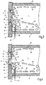
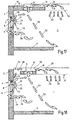
- FIG. 3 shows an embodiment of an arrangement for the air conditioning of a room 1, which differs from the embodiment of the FIG. 1 differs in that instead of a ceiling device 13, a sill device 32 is used, which is disposed below the window 4 adjacent to the facade wall 2 and formed as a fan coil 12. It has at its upper end face 33 an air inlet opening 14 and in the lower zone of its front side 34, an air outlet opening 15, which is associated with a heat exchanger 17. Above the heat exchanger 17 is located inside the sill device 32, a fan 16th
- FIG. 3 In the embodiment of FIG. 3 is the summer case. This means that relatively warm outside air 26 flows through the upper region of the outside air opening cross-section 8 of the window 4 into the room 1, where it reaches the occupied zone in the area of the ceiling 10. Cooler room air 29 flows in the middle zone of the room 1 in the direction of the facade wall 2 and thereby enters partially through the lateral areas of the outside air opening cross-section 8 to the outside and partially into the air inlet opening 14 of the fan coil 12 a. This proportion of room air is conveyed by the fan 16 and passes through the heat exchanger 17, which assumes a cooling function.
- a centrally treated coolant 27 is metered by the common control or regulating unit 25, which also controls or regulates the other parameters in common, that already combined to the embodiments of the Figures 1 and 2 were called.
- the cooled, the parapet 32 leaving air flows as a source ventilation to form a cold air lake according to the arrows 35 in the region of the bottom zone of the room 1 in the occupied zone.
- the embodiment of FIG. 4 differs from the embodiment of FIG. 3 only in that the window sash 6 does not have a horizontal tilting axis 7 in its lower region, but has a horizontal tilting axis 7 approximately in its middle zone, ie, in the exemplary embodiment of FIG. 4 Not only in the side zones of the window sash 6, but also in the upper and in the lower zone of the sash 6 in its open position, an outside air opening cross-section 8 created.
- the embodiment of FIG. 4 is also the summer case.
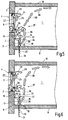
- FIG. 5 shows an embodiment of an arrangement for the air conditioning of a room 1 that the embodiment of the FIG. 3 equivalent.
- the FIG. 6 shows an embodiment of the embodiment of the FIG. 4 equivalent. Different from the figures of the embodiments of FIGS. 3 and 4 is in the embodiments of FIGS. 5 and 6 only that in the two latter embodiments of the winter case exists. In the embodiments of the FIGS. 5 and 6 it is also a source ventilation. It can be seen that cool outside air 26 partially flows into the air inlet opening 14 of the sill device 32 and partially enters the room 1. The inflow of the outside air 26 takes place in the lower side region of the window 4 (exemplary embodiment of FIGS FIG. 5 ) And additionally in the lower longitudinal zone of the window 4 in the embodiment of FIG.
- each of a fan coil 12th be formed.
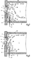
- the arrangement of FIGS. 7 and 8 corresponds essentially to the arrangement of FIG. 5
- the sill device 32 sucks in the embodiments of FIGS. 7 and 8 Room air in the lower zone of its front 34, so that there is the air inlet opening 14 and the upwardly facing, lying below the window 4 end face 33 of the sill device 32 has the air outlet opening 15, so far as the embodiment of the FIG. 5 with respect to the air inlet opening 14 and the air outlet opening 15 according to inverse conditions.
- FIG. 7 concerns the summer fall; the FIG. 8 the winter fall.
- a combined control is performed by a controller 25 that controls or regulates at least the following: outside air opening area 8, air volume flow 18 from the sill 32 and volumetric flow of a heating or cooling means 31, 27 of the heat exchanger 17 of the sill device 32.
- FIG. 8 is the winter case, ie, cold outside air 26 flows in the lower regions of the side zone of the window 4 in the room 1, and thereby meets coming from the sill device 32 warm air.
- This warm air results from in the bottom zone of the room 1 sucked in room air 29, which is heated in the heat exchanger 17 and blown obliquely upward along the window 4 in the room 1.
- This blown air impinges on the cool outside air 26, so that there is formed a mixing zone 39 in front of the window 4 within the space 1.
- the mixed air thus formed rises into the area of the ceiling zone of the room 1 and from there into the occupied zone.
- Room air 29 flows in the upper region of the outside air opening cross-section 8 through the open window 4 to the outside.
- FIGS. 9 and 10 correspond to the embodiment of FIG. 3
- a bottom device 40 is provided instead of the sill device 32.
- This floor unit 40 is recessed in the bottom 9 of the room 1 and is located below the window 4, adjacent to the facade wall 2.
- the floor unit 40 is formed as a fan coil 12 and has a fan 16 and a heat exchanger 17.
- the heat exchanger 17 is in Summerfall the FIG. 9 with a coolant 27 and winter in the FIG. 10 with a heating means 31 each metered by a volume flow adjuster 20, supplied.
- the control or regulating device 25 applies the corresponding, which has already been said to the other embodiments.
- the floor unit 40 is oriented such that an air inlet opening 14 is farther away from the facade wall 2 and an air outlet opening 15 is located relatively close to the facade wall 2 in the region of the bottom 9.
- FIG. 9 enters through the outside air opening cross-section 8 warm outside air 26 in the room 1 and sweeps along the ceiling zone to get to the occupied zone.
- the floor unit 40 draws in via the air inlet opening 14 room air 29 as air volume flow 18, which is cooled in the heat exchanger 17 and blown out of the air outlet opening 15 upwards in the area of the facade wall 2 in the room 1.
- the air rises and thereby meets with outflowing room air 29, which leaves the room 1 from the side areas of the opened window 4.
- the mixed air thus formed lowers again at the level of the window 4 inside the room and then flows away from the window in the direction of the occupied zone of the room.
- the winter case is in the design as a floor fan convector with mixed source ventilation. Since there is relatively cold outside air 26, this flows into the lower part of the window 4 in the room 1. Warmer room air 29 flows in the upper area of the window 4 from the room 1 outside. The air inlet opening 14 of the floor unit 40 sucks in room air 29 as air volume flow 18 and heats it in the heat exchanger 17. The heated air exits from the air outlet opening 15 in the region of the bottom 9 near the facade wall 2 upwards and meets there in the window sill and in an overlying zone on the outside air 26 flowing through the side areas of the window 4, so that air mixing takes place here. This mixed air then rises obliquely upward with increasing distance to the facade wall 2 to in the ceiling area of the room 1 and finally comes out of the FIG. 10 not visible living zone of room 1.
- the combinatorial control or regulating device 25 which has already been mentioned several times, also acts here.
- FIG. 11 again illustrates the execution of the fan convector 12 as a base unit 40 with heat exchanger 17 and fan 16.
- the installation is made in alignment with the bottom 9 of the room 1, ie, the top 41 of the bottom 9 is aligned with the top 42 of the floor unit 40th Das Boden réelle 40 adjoins the facade wall 2 of the room 1.
- FIG. 12 illustrates once again the execution of the fan coil 12 as parapet device 32 with fan 16 and heat exchanger 17.
- the heat exchanger 17 extends over the entire front side 34 of the fan coil 12; the fan 16 is located next to the heat exchanger 17 in the region of the lower half.
- FIG. 13 shows an embodiment that the the FIG. 12 equivalent. Therefore, there is also a sill device 32, but in contrast to the embodiment of FIG. 12 -
- the heat exchanger 17 is disposed below the fan 16 arranged above it.
- FIG. 14 illustrates the execution of an air conditioner 11 not in the form of a fan convector, but in the form of an induction device.
- all embodiments described above, which include a fan coil 12, instead of this fan coil 12, could also have an induction unit 43. It is also possible; to accommodate in a room 1 a plurality of air conditioners 11, which may be either all fan coil units or all induction units or mixed, fan coil (s) and induction unit (s).
- the induction device has an air distribution box 44, which is supplied with centrally processed air and / or with room air and / or outside air by means of a corresponding device, such as a fan or by connection to a pressure air line.
- the air of the Heilverteilkastens 44 enters from induction nozzles 45 in a mixing chamber 46 a.
- a mixing chamber 46 a In the FIG. 14
- only one induction nozzle 45 is shown.
- FIGS. 11 to 14 resulting devices in different mounting positions in the To arrange space 1 so that they form either a ceiling device 13, a sill device 32 or a floor unit 40.
- FIGS. 15 and 16 illustrate the drive means 21 for the actuation of the window sash 6.
- the drive means 21 has a housing 24 in which an electric motor with gear is arranged.
- the control or regulating device 25 is also arranged in the housing 24.
- the arrangement is such that the housing 24 is mounted on the window sash 6 and that the base body 49 is attached to the frame 5 of the window 4.
- the control or regulating device 25 gives corresponding signals to the drive of the drive device 21, so that the eccentric 47 is actuated and a force is transmitted via the articulated rod 48 to the base body 49, which causes it to open or close or to adjust the Outside air opening cross section 8 comes.
- the arrangement is preferably made such that a square protrudes from the underside of the housing 24, which cooperates with the drive rod system (not shown) of the window 4 and can perform a locking or unlocking of the window 4. In operation, therefore, the window is first unlocked and then moved to a corresponding open position. Accordingly, when the window is closed, the window sash 6 is first moved into the closed position and then the locking is effected by means of the drive rod system.
- the invention may include further sensors which detect, for example, certain areas of the room in terms of temperature. Furthermore, it is possible to additionally or alternatively sense the wind pressure or the wind speed and to take it into account in the control or regulation.
- tilting windows are used as windows.
- the invention can also be applied to rotary windows if the window drive is designed accordingly.
- the axis of rotation is preferably in one of the two side regions of the window sash.
- the mentioned source vents ensure a high temperature stratification in the summer, since low air velocities are present.
- the cooled air stays on the floor and does not flow over the window. It results in a low energy loss.
- the source ventilation has the advantage that in the heating mode, a cold air drop is prevented on the window pane. Heat loss from hot air escaping through the window can be considered low.
- the mentioned mixed-source ventilation leads in summer to a lower temperature stratification compared to a pure displacement ventilation, as a room air admixing takes place. A risk of short circuit can be prevented by appropriate steering of the air.
- the mixed-displacement ventilation in the heating mode prevents a cold air drop at the window pane. Shielding by fans, which is more effective than in the case of forced ventilation, can preferably take place. The heat loss through escaping through the window warm air can be kept very low, so they do not interfere appear.
- the advantage that warm ceiling air is sucked in which has a higher cooling performance. It sets a very low temperature stratification.
- control or regulating method according to the invention in particular as another, to be taken into account by the combined control Parameters that take into account the outside temperature. Furthermore, it is additionally or alternatively possible to sense the internal temperature, in particular in the floor area, in order to avoid low floor temperatures.
- the aim of the window ventilation is to cover the fresh air requirement of the room.
- inexpensive fresh air is used due to the window ventilation, which is aftertreated to improve the indoor climate.
- the fresh air requirement depends on the number of people in the room and can be pretended accordingly.
- the control and / or regulation then sets the appropriate outside air opening area.
- the pressure conditions on the facade of the outside air opening having space and / or the pressure conditions at the outside air opening are taken into account. If there is a high facade pressure, a small opening is set. The fresh air requirement remains constant. At low facade pressure, a large outside air opening is set, while also the fresh air requirement is kept constant.
- the outside air opening is closed and optionally another outside air opening, in particular another window, is automatically opened, in which there is overpressure.
- this procedure can only be carried out if the conditions mentioned are present.
- the controller or controller may include a map in which a desired value is set. By measuring the temperature and / or pressure and / or velocity of the air at the window and the room temperature, an actual value is determined. Now window drive, valves or the heat exchanger and speed of the fan or fans are controlled in order to come to the required target value.
- the fan speed of the air conditioner or the air conditioning units preferably also according to the ventilation method, which can / can be operated in source ventilation or mixed-source ventilation. Furthermore, there is a dependency on the placement of the air conditioner or devices, in particular whether this or these are arranged on the ceiling, the balustrade and / or the floor. In this case, it is possible for the air conditioning unit (s) to realize a source ventilation and / or mixed source ventilation.
- breather in which the outside air opening, in particular the window or the like is opened periodically. Also a change of operation - window on, air conditioning off or window closed, air conditioning on - is conceivable.
- FIGS. 17 and 18 show two further embodiments of an inventive arrangement in which a so-called "silent cooling" is realized.
- the summer case ie, the room 1 should be cooled.
- FIG. 17 is in the ceiling 10 of the room 1 as an air conditioner 11, only a heat exchanger 17 is provided air drive means, in particular a fan, are not available.
- the heat exchanger 17 is installed flush with the ceiling 10 and has a Jardinzziströmkanal 51 on its side facing away from the room.
- the ceiling 10 starts from the facade wall 2 of the room 1 and ends at a distance from the facade wall 2. This allows room air 29 rise above the ceiling level 52 and enter the Jardin povertyzuströmkanal 51 and flow to the heat exchanger 17.
- the room air 29 is cooled and then enters from top to bottom - coming from the ceiling area - in the room 1 again.
- Outside air 26 enters through the outside air opening cross-section 8 in the upper region of the window 4 in the room 1 and meets the coming of the heat exchanger 17 cooled room air 29. It results in a mixing and the mixed air decreases according to the oblique arrows 53 in the Living zone of the room 1. Room air 29 can leave the room 1 via the side areas of the opened window 4.
- FIG. 18 is different from that of FIG. 17 in that the ceiling 10 leaves the facade wall 2 a free space 55, which forms an air inflow channel 56.
- the ceiling 10 leaves the facade wall 2 a free space 55, which forms an air inflow channel 56.
- the air conditioner 11 only the heat exchanger 17 and no air drive means.
- warm room air 29 rises due to their low specific weight and is due to the cooling heat exchanger 17 led.
- the now cooler air with its higher specific gravity then sinks back into the room 1.
- outside air enters the room 1.
- the conditions for combined control and / or regulation already presented for the above exemplary embodiments otherwise apply correspondingly. At least by means of this control and / or regulation of the outside air opening cross-section and the volume flow of a heating and / or cooling medium, in particular a coolant, controlled or regulated by the heat exchanger 17 of the air conditioner 11.
Landscapes
- Engineering & Computer Science (AREA)
- Chemical & Material Sciences (AREA)
- Combustion & Propulsion (AREA)
- Mechanical Engineering (AREA)
- General Engineering & Computer Science (AREA)
- Air Conditioning Control Device (AREA)
- Central Air Conditioning (AREA)
Claims (31)
- Procédé pour la climatisation d'un local, par lequel l'air extérieur peut pénétrer dans le local au travers d'une ouverture pour air extérieur non reliée à un climatiseur et par lequel l'air du local peut être conditionné à l'aide de l'au moins un climatiseur, caractérisé par la commande et/ou la régulation combinées d'au moins des grandeurs suivantes :la section d'ouverture pour l'air extérieur etle débit volumique d'un agent de chauffage et/ou de refroidissement dans un ou plusieurs échangeurs de chaleur du climatiseur.
- Procédé selon la revendication 1, caractérisé par la commande et/ou régulation combinées de la grandeur supplémentaire : le débit volumique d'air du climatiseur.
- Procédé selon l'une des revendications précédentes, caractérisé en ce, que soit utilisé un ventilo-convecteur en tant que climatiseur.
- Procédé selon l'une des revendications précédentes, caractérisé en ce, que soit utilisé un appareil à induction en tant que climatiseur.
- Procédé selon l'une des revendications précédentes, caractérisé en ce, que soient utilisés en tant que climatiseur un appareil d'installation sur le sol, un appareil mural, en particulier un appareil d'allège, et/ou un appareil plafonnier.
- Procédé selon l'une des revendications précédentes, caractérisé en ce, que le climatiseur, le ventilo-convecteur et/ou l'appareil à induction amènent aussi de l'air extérieur dans le local.
- Procédé selon la revendication 5, caractérisé en ce, que sur l'appareil à induction, l'aspiration de l'air extérieur s'effectue à l'aide d'un ventilateur d'apport d'air.
- Procédé selon la revendication 6 ou 7, caractérisé en ce, que l'air extérieur soit aspiré à travers l'ouverture pour air extérieur et/ou à travers un passage d'air extérieur, en particulier à travers une fenêtre ou une porte extérieure.
- Procédé selon l'une des revendications précédentes, caractérisé en ce, que le climatiseur, le ventilo-convecteur et/ou l'appareil à induction soient approvisionnés par de l'air primaire conditionné de manière centralisée.
- Procédé selon l'une des revendications précédentes, caractérisé en ce, que le local soit essentiellement climatisé à l'aide d'une ventilation par déplacement.
- Procédé selon l'une des revendications précédentes, caractérisé en ce, que le local soit essentiellement climatisé à l'aide d'une ventilation par déplacement mixte.
- Procédé selon l'une des revendications précédentes, caractérisé en ce, que l'ouverture pour air extérieur soit réalisée par l'ouverture - en particulier par basculement ou ouverture par rotation - d'une fenêtre, d'une porte ou d'une structure similaire.
- Dispositif pour la climatisation d'un local (1), par lequel de l'air extérieur (26) peut pénétrer dans le local (1) au travers d'une ouverture pour air extérieur non reliée à un climatiseur (11) et par lequel de l'air du local (29) peut être conditionné à l'aide de l'au moins un climatiseur (11), caractérisé par un système de commande et/ou de régulation (25) pour la commande et/ou régulation combinées d'au moins des grandeurs suivantes :la section d'ouverture pour l'air extérieur (8) etle débit volumique d'un agent de chauffage et/ou de refroidissement (31, 27) dans un ou plusieurs échangeurs de chaleur (17) du climatiseur (11).
- Dispositif selon la revendication 13, caractérisé par le système de commande et/ou de régulation (25) pour la commande et/ou régulation combinées de la grandeur supplémentaire suivante : le débit volumique d'air (18) du climatiseur (11).
- Dispositif selon l'une des revendications précédentes, caractérisée en ce, que le climatiseur (11) soit un ventilo-convecteur (12) et/ou un appareil à induction (43).
- Dispositif selon l'une des revendications précédentes, caractérisé en ce, que le climatiseur soit un (pur) appareil à recirculation d'air.
- Dispositif selon l'une des revendications précédentes, caractérisée en ce, que le ventilo-convecteur (12) soit un ventilo-convecteur (12) central ou décentralisé.
- Dispositif selon l'une des revendications précédentes, caractérisée en ce, que l'appareil à induction (43) soit un appareil à induction (43) central ou décentralisé.
- Dispositif selon l'une des revendications précédentes, caractérisé en ce, que l'ouverture pour air extérieur soit formée par la section d'ouverture d'une fenêtre (4), d'une porte ou d'une structure similaire faisant partie du local (1).
- Dispositif selon l'une des revendications précédentes, caractérisé en ce, que la fenêtre (4), la porte ou une structure similaire comporte un dispositif d'entraînement (21) pouvant être commandé ou régulé pour le réglage de la section d'ouverture.
- Dispositif selon l'une des revendications précédentes, caractérisé en ce, que le dispositif d'entraînement (21) actionne l'ouvrant de fenêtre (6), le vantail de porte ou une structure similaire de manière motorisée en fonction d'un référentiel du système de commande ou de régulation (25).
- Dispositif selon l'une des revendications précédentes, caractérisé en ce, que le dispositif d'entraînement (21) actionne un dispositif de verrouillage (23) de la fenêtre (4), de la porte ou d'une structure similaire pour déverrouiller ou verrouiller l'ouvrant de fenêtre (6), le vantail de porte ou une structure similaire.
- Dispositif selon l'une des revendications précédentes, caractérisé en ce, que le système de commande ou de régulation (25) soit affecté au dispositif d'entraînement (21).
- Dispositif selon l'une des revendications précédentes, caractérisé en ce, que le système de commande ou de régulation (25) et le dispositif d'entraînement (21) soient installés dans un boîtier commun (24) ou que les deux dispositifs (25, 21) soient installés dans des boîtiers séparés.
- Dispositif selon l'une des revendications précédentes, caractérisé en ce, que le dispositif d'entraînement (21) et le système de commande ou de régulation (25) soient installés au niveau de la fenêtre (4), de la porte ou d'une structure similaire.
- Dispositif selon l'une des revendications précédentes, caractérisé en ce, que le dispositif d'entraînement (21) et le système de commande ou de régulation (25) soient installés au niveau de l'ouvrant de fenêtre (6), du vantail de porte ou d'une structure similaire.
- Dispositif selon l'une des revendications précédentes, caractérisé en ce, que le ventilo-convecteur (12) soit un appareil d'installation sur le sol, un appareil mural, en particulier un appareil d'allège, et/ou un appareil plafonnier (40, 32, 13).
- Dispositif selon l'une des revendications précédentes, caractérisé en ce, que l'appareil à induction (43) soit un appareil d'installation sur le sol, un appareil mural, en particulier un appareil d'allège, et/ou un appareil plafonnier (40, 32, 13).
- Dispositif selon l'une des revendications précédentes, caractérisé en ce, que le climatiseur soit un appareil d'installation sur le sol, un appareil mural, en particulier un appareil d'allège, et/ou un appareil plafonnier (40, 32, 13).
- Dispositif selon l'une des revendications précédentes, caractérisé en ce, que soient logés ou montés, au niveau de la fenêtre, de la porte ou dans le boîtier commun du système de commande ou de régulation (25), des capteurs pour l'enregistrement de la température de l'air extérieur et intérieur et/ou de la pression de l'air extérieur et/ou de la vitesse de l'air extérieur.
- Dispositif selon l'une des revendications précédentes, caractérisé en ce, que le ventilo-convecteur (12) et/ou l'appareil à induction (43) et/ou le climatiseur soient installés dans la zone de la façade du local à climatiser.
Applications Claiming Priority (2)
| Application Number | Priority Date | Filing Date | Title |
|---|---|---|---|
| DE10346732 | 2003-10-08 | ||
| DE10346732A DE10346732A1 (de) | 2003-10-08 | 2003-10-08 | Verfahren und Anordnung zur Klimatisierung eines Raumes |
Publications (3)
| Publication Number | Publication Date |
|---|---|
| EP1522799A2 EP1522799A2 (fr) | 2005-04-13 |
| EP1522799A3 EP1522799A3 (fr) | 2006-11-02 |
| EP1522799B1 true EP1522799B1 (fr) | 2016-11-09 |
Family
ID=34306323
Family Applications (1)
| Application Number | Title | Priority Date | Filing Date |
|---|---|---|---|
| EP04022266.3A Expired - Lifetime EP1522799B1 (fr) | 2003-10-08 | 2004-09-18 | Méthode et installation pour la climatisation d'une pièce |
Country Status (2)
| Country | Link |
|---|---|
| EP (1) | EP1522799B1 (fr) |
| DE (1) | DE10346732A1 (fr) |
Families Citing this family (10)
| Publication number | Priority date | Publication date | Assignee | Title |
|---|---|---|---|---|
| DE102007041383B4 (de) * | 2007-08-31 | 2009-10-22 | K + G Pneumatik Gmbh | Rauch- und Wärmeabzugs- und Lüftungseinrichtung umfassend Rauch- und Wärmeabzugs- und Lüftungsgeräte mit jeweils einem motorischen Antrieb |
| DE102008050444C5 (de) * | 2008-10-08 | 2015-03-26 | Ltg Aktiengesellschaft | Verfahren zur Belüftung eines Raumes |
| DE102009009109B3 (de) * | 2009-02-16 | 2010-10-07 | Howatherm-Klimatechnik Gmbh | Verfahren zur Belüftung eines Raumes |
| DE102009016418B4 (de) * | 2009-04-04 | 2015-08-27 | Stefan Plüth | Verfahren zur Klimatisierung eines Raumes sowie dafür vorgesehene Vorrichtung |
| CH705961B1 (de) * | 2012-01-05 | 2016-06-30 | Wesco Ag | Verfahren zur Steuerung eines Raumlüftungssystems. |
| DE102013207449A1 (de) * | 2013-04-24 | 2014-10-30 | Dürr Systems GmbH | Verfahren zum Konditionieren von Luft und Konditionieranlage |
| WO2016036284A1 (fr) * | 2014-09-02 | 2016-03-10 | Telefonaktiebolaget L M Ericsson (Publ) | Appareil pour ventilation d'enceinte avec batterie |
| CN111720985A (zh) * | 2020-05-27 | 2020-09-29 | 苏州新森智能科技有限公司 | 一种基于安卓系统的室内新风控制器 |
| CN111720957A (zh) * | 2020-05-27 | 2020-09-29 | 苏州新森智能科技有限公司 | 一种被动房智能新风空调控制系统 |
| JP7643983B2 (ja) * | 2021-10-12 | 2025-03-11 | 株式会社Nttファシリティーズ | 空調装置 |
Family Cites Families (6)
| Publication number | Priority date | Publication date | Assignee | Title |
|---|---|---|---|---|
| DE4023673A1 (de) * | 1990-07-26 | 1992-02-06 | Vedder Gmbh Geb | Steuer- und regelsystem fuer bewegliche schutzeinrichtungen |
| DE19826567C2 (de) * | 1998-06-15 | 2002-06-27 | Ltg Holding Gmbh | Verfahren zum Klimatisieren eines Raumes sowie Einrichtung zum Klimatisieren des Raumes |
| DE20008641U1 (de) * | 2000-05-13 | 2000-08-03 | LTG Aktiengesellschaft, 70435 Stuttgart | Vorrichtung zum Klimatisieren eines Raumes |
| DE10064939C2 (de) * | 2000-12-23 | 2003-06-26 | Ltg Ag | Lufttechnische Einrichtung für einen Raum |
| EP1225399A1 (fr) * | 2001-01-18 | 2002-07-24 | Holding Aktiengesellschaft Belimo | Dispositif de surveillance et de commande de la ventilation naturelle de pièces et utilisation de ce dispositif |
| DE10164721B4 (de) * | 2001-02-02 | 2006-05-04 | Ltg Aktiengesellschaft | Raumlufttechnische Einrichtung |
-
2003
- 2003-10-08 DE DE10346732A patent/DE10346732A1/de not_active Withdrawn
-
2004
- 2004-09-18 EP EP04022266.3A patent/EP1522799B1/fr not_active Expired - Lifetime
Also Published As
| Publication number | Publication date |
|---|---|
| EP1522799A2 (fr) | 2005-04-13 |
| DE10346732A1 (de) | 2005-05-19 |
| EP1522799A3 (fr) | 2006-11-02 |
Similar Documents
| Publication | Publication Date | Title |
|---|---|---|
| EP2594725B1 (fr) | Fenêtre | |
| EP2405207B1 (fr) | Dispositif de climatisation intégrable au plafond | |
| DE10010832C1 (de) | Vorrichtung zur Temperierung und/oder Belüftung eines Raumes | |
| EP1918650B1 (fr) | Procédé de climatisation d'une pièce et dispositif de climatisation | |
| EP0044560A2 (fr) | Installation d'aérage pour des espaces ventilés en circulation forcée | |
| EP1522799B1 (fr) | Méthode et installation pour la climatisation d'une pièce | |
| DE19548599C2 (de) | Lüftungssystem für die Räume von Gebäuden | |
| EP0164111B1 (fr) | Fenêtre composée insonorisante et calorifuge avec un dispositif d'aération | |
| DE3341827A1 (de) | Lueftungssystem fuer die raeume von gebaeuden | |
| EP0657702B1 (fr) | Dispositif pour la génération de deux rideaux d'air à sens de circulation opposée | |
| AT500559B1 (de) | Raumlufttechnische einrichtung | |
| WO2009027049A1 (fr) | Système d'aération de façade | |
| DE3728698A1 (de) | Klimaanlage | |
| DE10253264C5 (de) | Dezentrale lufttechnische Einrichtung sowie Verfahren zum dezentralen Heizen oder Kühlen eines Raumes | |
| DE8713390U1 (de) | Lüftungsgerät zum Abführen von Abluft aus Räumen | |
| EP0358121A2 (fr) | Fenêtre aérée | |
| EP2180269B1 (fr) | Dispositif d'aération de pièce hybride | |
| DE29518108U1 (de) | Gerät zur Belüftung von Räumen | |
| EP1331455A1 (fr) | Ventilateur et méthode de régulation du ventilateur | |
| EP1331453A1 (fr) | Ventilateur | |
| DE202004012404U1 (de) | Vorrichtung zum Isolieren und Temperieren von Gebäuden | |
| DE29615791U1 (de) | Zweischalige Gebäudefassade | |
| EP1724533B1 (fr) | Système de traitement d'air intérieure et méthode correspondante | |
| DE19719367A1 (de) | Gebäude | |
| DE10247016A1 (de) | Lüfter |
Legal Events
| Date | Code | Title | Description |
|---|---|---|---|
| PUAI | Public reference made under article 153(3) epc to a published international application that has entered the european phase |
Free format text: ORIGINAL CODE: 0009012 |
|
| AK | Designated contracting states |
Kind code of ref document: A2 Designated state(s): AT BE BG CH CY CZ DE DK EE ES FI FR GB GR HU IE IT LI LU MC NL PL PT RO SE SI SK TR |
|
| AX | Request for extension of the european patent |
Extension state: AL HR LT LV MK |
|
| PUAL | Search report despatched |
Free format text: ORIGINAL CODE: 0009013 |
|
| AK | Designated contracting states |
Kind code of ref document: A3 Designated state(s): AT BE BG CH CY CZ DE DK EE ES FI FR GB GR HU IE IT LI LU MC NL PL PT RO SE SI SK TR |
|
| AX | Request for extension of the european patent |
Extension state: AL HR LT LV MK |
|
| 17P | Request for examination filed |
Effective date: 20070502 |
|
| AKX | Designation fees paid |
Designated state(s): AT BE BG CH CY CZ DE DK EE ES FI FR GB GR HU IE IT LI LU MC NL PL PT RO SE SI SK TR |
|
| 17Q | First examination report despatched |
Effective date: 20111021 |
|
| GRAP | Despatch of communication of intention to grant a patent |
Free format text: ORIGINAL CODE: EPIDOSNIGR1 |
|
| INTG | Intention to grant announced |
Effective date: 20160421 |
|
| GRAS | Grant fee paid |
Free format text: ORIGINAL CODE: EPIDOSNIGR3 |
|
| GRAA | (expected) grant |
Free format text: ORIGINAL CODE: 0009210 |
|
| AK | Designated contracting states |
Kind code of ref document: B1 Designated state(s): AT BE BG CH CY CZ DE DK EE ES FI FR GB GR HU IE IT LI LU MC NL PL PT RO SE SI SK TR |
|
| REG | Reference to a national code |
Ref country code: GB Ref legal event code: FG4D Free format text: NOT ENGLISH |
|
| REG | Reference to a national code |
Ref country code: AT Ref legal event code: REF Ref document number: 844312 Country of ref document: AT Kind code of ref document: T Effective date: 20161115 Ref country code: CH Ref legal event code: EP |
|
| REG | Reference to a national code |
Ref country code: IE Ref legal event code: FG4D Free format text: LANGUAGE OF EP DOCUMENT: GERMAN |
|
| REG | Reference to a national code |
Ref country code: DE Ref legal event code: R096 Ref document number: 502004015373 Country of ref document: DE |
|
| REG | Reference to a national code |
Ref country code: CH Ref legal event code: NV Representative=s name: OFFICE ERNEST T. FREYLINGER S.A., CH |
|
| REG | Reference to a national code |
Ref country code: NL Ref legal event code: MP Effective date: 20161109 |
|
| PG25 | Lapsed in a contracting state [announced via postgrant information from national office to epo] |
Ref country code: SE Free format text: LAPSE BECAUSE OF FAILURE TO SUBMIT A TRANSLATION OF THE DESCRIPTION OR TO PAY THE FEE WITHIN THE PRESCRIBED TIME-LIMIT Effective date: 20161109 Ref country code: GR Free format text: LAPSE BECAUSE OF FAILURE TO SUBMIT A TRANSLATION OF THE DESCRIPTION OR TO PAY THE FEE WITHIN THE PRESCRIBED TIME-LIMIT Effective date: 20170210 Ref country code: NL Free format text: LAPSE BECAUSE OF FAILURE TO SUBMIT A TRANSLATION OF THE DESCRIPTION OR TO PAY THE FEE WITHIN THE PRESCRIBED TIME-LIMIT Effective date: 20161109 |
|
| PG25 | Lapsed in a contracting state [announced via postgrant information from national office to epo] |
Ref country code: PL Free format text: LAPSE BECAUSE OF FAILURE TO SUBMIT A TRANSLATION OF THE DESCRIPTION OR TO PAY THE FEE WITHIN THE PRESCRIBED TIME-LIMIT Effective date: 20161109 Ref country code: PT Free format text: LAPSE BECAUSE OF FAILURE TO SUBMIT A TRANSLATION OF THE DESCRIPTION OR TO PAY THE FEE WITHIN THE PRESCRIBED TIME-LIMIT Effective date: 20170309 Ref country code: ES Free format text: LAPSE BECAUSE OF FAILURE TO SUBMIT A TRANSLATION OF THE DESCRIPTION OR TO PAY THE FEE WITHIN THE PRESCRIBED TIME-LIMIT Effective date: 20161109 Ref country code: FI Free format text: LAPSE BECAUSE OF FAILURE TO SUBMIT A TRANSLATION OF THE DESCRIPTION OR TO PAY THE FEE WITHIN THE PRESCRIBED TIME-LIMIT Effective date: 20161109 |
|
| PG25 | Lapsed in a contracting state [announced via postgrant information from national office to epo] |
Ref country code: EE Free format text: LAPSE BECAUSE OF FAILURE TO SUBMIT A TRANSLATION OF THE DESCRIPTION OR TO PAY THE FEE WITHIN THE PRESCRIBED TIME-LIMIT Effective date: 20161109 Ref country code: SK Free format text: LAPSE BECAUSE OF FAILURE TO SUBMIT A TRANSLATION OF THE DESCRIPTION OR TO PAY THE FEE WITHIN THE PRESCRIBED TIME-LIMIT Effective date: 20161109 Ref country code: CZ Free format text: LAPSE BECAUSE OF FAILURE TO SUBMIT A TRANSLATION OF THE DESCRIPTION OR TO PAY THE FEE WITHIN THE PRESCRIBED TIME-LIMIT Effective date: 20161109 Ref country code: RO Free format text: LAPSE BECAUSE OF FAILURE TO SUBMIT A TRANSLATION OF THE DESCRIPTION OR TO PAY THE FEE WITHIN THE PRESCRIBED TIME-LIMIT Effective date: 20161109 Ref country code: DK Free format text: LAPSE BECAUSE OF FAILURE TO SUBMIT A TRANSLATION OF THE DESCRIPTION OR TO PAY THE FEE WITHIN THE PRESCRIBED TIME-LIMIT Effective date: 20161109 |
|
| REG | Reference to a national code |
Ref country code: DE Ref legal event code: R097 Ref document number: 502004015373 Country of ref document: DE |
|
| PG25 | Lapsed in a contracting state [announced via postgrant information from national office to epo] |
Ref country code: IT Free format text: LAPSE BECAUSE OF FAILURE TO SUBMIT A TRANSLATION OF THE DESCRIPTION OR TO PAY THE FEE WITHIN THE PRESCRIBED TIME-LIMIT Effective date: 20161109 Ref country code: BG Free format text: LAPSE BECAUSE OF FAILURE TO SUBMIT A TRANSLATION OF THE DESCRIPTION OR TO PAY THE FEE WITHIN THE PRESCRIBED TIME-LIMIT Effective date: 20170209 |
|
| PLBE | No opposition filed within time limit |
Free format text: ORIGINAL CODE: 0009261 |
|
| STAA | Information on the status of an ep patent application or granted ep patent |
Free format text: STATUS: NO OPPOSITION FILED WITHIN TIME LIMIT |
|
| 26N | No opposition filed |
Effective date: 20170810 |
|
| PG25 | Lapsed in a contracting state [announced via postgrant information from national office to epo] |
Ref country code: SI Free format text: LAPSE BECAUSE OF FAILURE TO SUBMIT A TRANSLATION OF THE DESCRIPTION OR TO PAY THE FEE WITHIN THE PRESCRIBED TIME-LIMIT Effective date: 20161109 |
|
| GBPC | Gb: european patent ceased through non-payment of renewal fee |
Effective date: 20170918 |
|
| PG25 | Lapsed in a contracting state [announced via postgrant information from national office to epo] |
Ref country code: MC Free format text: LAPSE BECAUSE OF FAILURE TO SUBMIT A TRANSLATION OF THE DESCRIPTION OR TO PAY THE FEE WITHIN THE PRESCRIBED TIME-LIMIT Effective date: 20161109 |
|
| REG | Reference to a national code |
Ref country code: IE Ref legal event code: MM4A |
|
| REG | Reference to a national code |
Ref country code: BE Ref legal event code: MM Effective date: 20170930 |
|
| PG25 | Lapsed in a contracting state [announced via postgrant information from national office to epo] |
Ref country code: LU Free format text: LAPSE BECAUSE OF NON-PAYMENT OF DUE FEES Effective date: 20170918 |
|
| REG | Reference to a national code |
Ref country code: FR Ref legal event code: ST Effective date: 20180531 |
|
| PG25 | Lapsed in a contracting state [announced via postgrant information from national office to epo] |
Ref country code: IE Free format text: LAPSE BECAUSE OF NON-PAYMENT OF DUE FEES Effective date: 20170918 Ref country code: GB Free format text: LAPSE BECAUSE OF NON-PAYMENT OF DUE FEES Effective date: 20170918 |
|
| PG25 | Lapsed in a contracting state [announced via postgrant information from national office to epo] |
Ref country code: BE Free format text: LAPSE BECAUSE OF NON-PAYMENT OF DUE FEES Effective date: 20170930 Ref country code: FR Free format text: LAPSE BECAUSE OF NON-PAYMENT OF DUE FEES Effective date: 20171002 |
|
| PG25 | Lapsed in a contracting state [announced via postgrant information from national office to epo] |
Ref country code: HU Free format text: LAPSE BECAUSE OF FAILURE TO SUBMIT A TRANSLATION OF THE DESCRIPTION OR TO PAY THE FEE WITHIN THE PRESCRIBED TIME-LIMIT; INVALID AB INITIO Effective date: 20040918 |
|
| PG25 | Lapsed in a contracting state [announced via postgrant information from national office to epo] |
Ref country code: CY Free format text: LAPSE BECAUSE OF NON-PAYMENT OF DUE FEES Effective date: 20161109 |
|
| PGFP | Annual fee paid to national office [announced via postgrant information from national office to epo] |
Ref country code: AT Payment date: 20190919 Year of fee payment: 16 |
|
| PGFP | Annual fee paid to national office [announced via postgrant information from national office to epo] |
Ref country code: CH Payment date: 20190919 Year of fee payment: 16 |
|
| PG25 | Lapsed in a contracting state [announced via postgrant information from national office to epo] |
Ref country code: TR Free format text: LAPSE BECAUSE OF FAILURE TO SUBMIT A TRANSLATION OF THE DESCRIPTION OR TO PAY THE FEE WITHIN THE PRESCRIBED TIME-LIMIT Effective date: 20161109 |
|
| PGFP | Annual fee paid to national office [announced via postgrant information from national office to epo] |
Ref country code: DE Payment date: 20200917 Year of fee payment: 17 |
|
| REG | Reference to a national code |
Ref country code: CH Ref legal event code: PL |
|
| REG | Reference to a national code |
Ref country code: AT Ref legal event code: MM01 Ref document number: 844312 Country of ref document: AT Kind code of ref document: T Effective date: 20200918 |
|
| PG25 | Lapsed in a contracting state [announced via postgrant information from national office to epo] |
Ref country code: CH Free format text: LAPSE BECAUSE OF NON-PAYMENT OF DUE FEES Effective date: 20200930 Ref country code: AT Free format text: LAPSE BECAUSE OF NON-PAYMENT OF DUE FEES Effective date: 20200918 Ref country code: LI Free format text: LAPSE BECAUSE OF NON-PAYMENT OF DUE FEES Effective date: 20200930 |
|
| REG | Reference to a national code |
Ref country code: DE Ref legal event code: R119 Ref document number: 502004015373 Country of ref document: DE |
|
| PG25 | Lapsed in a contracting state [announced via postgrant information from national office to epo] |
Ref country code: DE Free format text: LAPSE BECAUSE OF NON-PAYMENT OF DUE FEES Effective date: 20220401 |